Electromagnetic Energy Sink
Abstract
The ideal black body fully absorbs all incident rays, that is, all propagating waves created by arbitrary sources. The known idealized realization of a black body is the perfectly matched layer (PML), widely used in numerical electromagnetics. However, ideal black bodies and PMLs do not interact with evanescent fields existing near any finite-size source, and the energy stored in these fields cannot be harvested. Here we introduce the concept of the ideal conjugate matched layer (CML), which fully absorbs energy of both propagating and evanescent fields of sources acting as an ideal sink for electromagnetic energy. Conjugate matched absorbers have exciting application potentials, as resonant attractors of electromagnetic energy into the absorber volume. We derive the conditions on the constitutive parameters of media which can serve as CML materials, numerically study the performance of planar and cylindrical CML and discuss possible realizations of such materials as metal-dielectric composites.
PACS numbers: 81.05.Xj, 78.67.Pt (metamaterials), 88.80.ht (wireless transmission), 52.25.Os (absorption in plasmas).
I Introduction
The theoretical concept of the ideal black body which completely absorbs all incident rays GK is widely used in thermodynamics, optics, and radio engineering. Many important applications would benefit from close-to-ideal absorbers, including light harvesting, thermal emission, stealth, decoupling of antennas and other devices, etc. Motivated by these prospects, significant research and development efforts have been devoted to realization of absorbers which would offer performance close to that of the ideal black body, see review papers absorber_review ; padilla . Most of the known results concern planar absorbers, effective for a limited range of incidence angles. Omnidirectional realizations using inhomogeneous lossy media have been proposed blackhole2 ; blackhole1 and an experimental test at microwave frequencies has been performed china_test . A theoretical possibility to perfectly absorb waves of all polarizations coming from all directions is based on the idea of the perfectly matched layer (PML) as a layer which produces no reflections PML ; PML_Gedney ; PML_Ziolk ; PML_active . All these concepts imply that the body fully absorbs all propagating waves incident on its surface, emulating the ideal black body. But are these objects truly perfect absorbers or can we perhaps do even better and extract energy also from evanescent fields created by arbitrary sources? Indeed, the perfectly matched layer produces no reflections and fully absorbs power of all propagating modes (in the ideal case, realizing the properties of the perfect black body), but evanescent fields of sources are not affected by the presence of the perfectly matched layer; thus, no energy is extracted from them. Basically, within the known paradigm of uniaxial perfectly matched layers PML_Gedney ; PML_active , there is a conundrum between perfect absorption of all propagating waves and extraction of power from evanescent fields. If the conditions for perfect absorption of propagating fields are satisfied, evanescent modes are not absorbed at all. If the parameters of the absorber are modified so that some power is extracted from evanescent fields of the source, the propagating modes are not any more fully absorbed. In other words, evanescent fields of sources contribute to absorbed power in lossy media, but within all known realization scenarios it appears that if the properties of lossy media are chosen so that all the propagating modes are perfectly absorbed, evanescent fields do not any more interact with the body.
A typical example is a possibility to extract power from near fields of small sources, which has been discussed in the context of hyperbolic media electromagnetics hyperbolic_review . Hyperbolic media are artificial materials (metamaterials), whose permittivity tensor is indefinite, so that the real parts of its different diagonal components have the opposite signs. Due to the hyperbolic shape of isofrequency contours, evanescent waves exciting a planar interface of a hyperbolic material sample are partially converted to propagating modes DipoleLineSource within the medium and can be effectively absorbed there if the material is lossy HyperbolicBlackbody ; MetamaterialSpontaneousEmission ; hyp_shalaev . However, lossy hyperbolic bodies are not effective absorbers for incident propagating waves. Actually, an interface between free space and a hyperbolic medium can be matched if the anisotropy axis is titled with respect to the interface, but only for one incidence angle Nefedov .
In this paper, we study possibilities to create bodies which would act as perfect absorbers for all spatial harmonics of incident radiation, both propagating and evanescent. Conceptually, such an ideal absorber is able to extract infinite power from a finite-size emitter located at a finite distance, limited only by the power of the source which feeds the emitting object (a generic antenna). This study is motivated by the results of theoretical studies which prove that a finite-size body, which is conjugate impedance matched with respect to its environment at all spatial spectrum components, has infinite relative absorptivity when compared to the classical ideal black body GK of the same size, e.g. Refs. Bobr ; unlimited_antenna ; SphericalPaper . However, to the best of our knowledge, only an idealized realization of such a conjugate matched absorber as a non-uniform, locally isotropic double-negative (DNG) sphere has been proposed in Ref. SphericalPaper . In a sense, such object acts as a perfect sink for all incident spherical waves characterized by arbitrary transverse wave numbers, but its practical realization is challenging because very low levels of material losses are required. Here, we show how one can possibly create absorbers which are nearly perfectly working with both propagating and evanescent incident waves using uniaxial DNG materials, both for planar boundaries and curved surfaces. In this new scenario, there are practical possibilities for realizations as well-studied uniaxial backward-wave structures (see the discussion in Section V).
Since our proposed structures are not only able to absorb all propagating waves but can also extract power from the evanescent modes, the total extracted power can go far beyond what can be attained with know metamaterial black holes blackhole2 ; blackhole1 and even the ideal black body. In other words, we can go beyond “the perfect absorber”. From the physical point of view, the conjugate matching condition for evanescent modes is similar to the condition of existence of resonant surface modes, which can help to increase exchange of thermal radiation between two closely located bodies thermo1 ; thermo_pendry ; thermo1a ; thermo2 . However, in the proposed scenario it is possible to realize the optimal conjugate matching for all modes, both propagating and evanescent, that is, create the ultimately effective sink for electromagnetic energy from objects located at arbitrary distances. The main focus of this paper is on harvesting energy from small sources in their near-field zone, but we also discuss more general realizations of perfect finite-size absorbers for far-zone sources (plane-wave illumination), that have been also proposed in paper SphericalPaper .
II Absorption of All Incident Modes
II.1 Eliminating Reflection or Maximizing Absorption
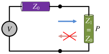
Our starting point is the classical circuit-theory concept of conjugate impedance matching of a load, which is the condition for maximizing the power delivered to the load from a generator. Referring to Fig. 1, showing an arbitrary time-harmonic voltage source with a complex internal impedance , which is loaded by a complex impedance , we can distinguish two different approaches to impedance matching Pozar . The first one, illustrated in Fig. 1, minimizes (nullifies) reflections from the load to the source by equalizing the two impedances: . In this case the power absorbed in the load equals to (here and in what follows we use rms values for the complex amplitudes of the time-harmonic quantities; the time dependence is , where ):
| (1) |
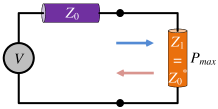
The second one, illustrated in Fig. 1, maximizes the power
| (2) |
that is transferred to the load by satisfying the conjugate matching condition: . Note that in this case reflections from the load are in general not zero, because the matching condition is satisfied only if these impedances are purely real. Obviously, if . With the goal to maximize absorption in the load, the optimal approach is to ensure that the load impedance is conjugate matched with the source impedance.
If the impedances are predominantly reactive (the imaginary parts of are large compared with the real parts), the power delivered to the load tends to zero when the load resistance tends to zero [eq. (1)], while for the conjugate matched load it diverges to infinity [eq. (2)]. In the general electromagnetics context, this resonant behavior suggests that conjugate matching wave impedances of two media, in the limit of zero losses, unlimited power can be delivered from sources in one medium into another medium. This fact was noticed in paper optimization , in studies of maximizing radiative heat flow between two bodies. As a possible approach to realizing the conjugate match condition for all modes, in paper optimization it was proposed to insert dense arrays of thin conducting wires into both bodies (orthogonally to the interface), which makes the wave impedances of a wide range of modes approximately real. This approach is clearly not possible if the sources are in free space, and in this paper we will study means to ensure all-mode conjugate matching by properly selecting the material parameters of the absorbing body.
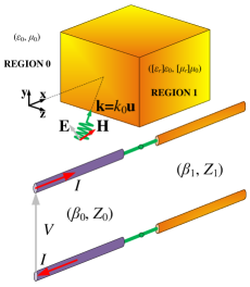
Let us consider an infinite planar interface between free space and a half-space filled by some lossy material, excited by electromagnetic fields created by some arbitrary sources in free space, as shown in Fig. 2. We can use the concept of conjugate matching to understand the conditions for maximizing the power absorbed in the medium. To do that, we expand the incident fields into plane-wave spatial Fourier components with the wave vectors (, where is the free-space wavenumber and u is a dimensionless vector. The axis is directed normally to the interface between free space and the absorbing medium and points from free space into the medium. To simplify considerations, without loss of generality we will consider fields of only one polarization — the TM polarization (magnetic field possesses a sole component and electric field vector lies on the plane) — and assume that the fields do not depend on the coordinate . The normal to the interface component of the propagation constant in free space reads , where . When , the excitation corresponds to propagating waves and when , we deal with exponentially decaying evanescent modes of free space. The corresponding TM wave impedance in vacuum (the ratio of the tangential to the interface field components) is expressed as
| (3) |
where is the free-space wave impedance. The branches of all square roots are defined as having positive real parts.
In view of our goal to conjugate match the impedances of all modes, we demand the uniaxial symmetry of the material tensors of the absorbing medium, with the axis directed normally to the interface (along ), to ensure a possibility of matching to the isotropic free space. Let us write the relative permittivity and permeability tensors as
| (10) |
The propagation constants of transverse magnetic (TM-polarized) plane waves in the medium read modeboo : with
| (11) |
where the real part of the square root is positive, ensuring decaying waves along the positive direction of the axis (away from the sources). The corresponding impedance equals
| (12) |
To understand the conditions for the optimal absorption of all modes we can use the concept of conjugate impedance matching for all plane-wave components of the fields. In the configuration of Fig. 2, the load impedance is the wave impedance of a certain mode in the medium and the source impedance is the impedance of the corresponding (the same ) mode in free space. The transmission-line model with voltage (corresponding to the electric field E) and current (measuring the magnetic field H) is also depicted at the bottom of Fig. 2, where the two lines with different propagation constants and wave impedances represent the source and the load, respectively.
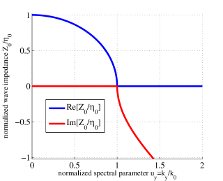
The variation of the normalized free-space wave impedance (with infinitesimally small losses added to ensure the correct choice of the square-root branch) of TM waves as a function of the relative tangential component of the propagation constant is shown in Fig. 2 (only positive are considered since all the impedance functions are even with respect to ). It is apparent that the quantity is positive real for (propagating modes) and negative imaginary for (evanescent modes). With the objective to maximize absorption of electromagnetic energy by the medium, we will next look for such constituent parameters that for all real values of .
II.2 Double-Negative Conjugate Matched Layer
Given the fact that the TM wave impedance of vacuum (3) is real for , the reflectionless matching is identical to conjugate matching for the propagating waves. Therefore, for that part of the incidence spectrum, we are searching for a uniaxial medium that does not reflect incoming traveling fields. Such a medium is the famous uniaxial perfectly matched layer (PML) with PML_Gedney
| (13) |
Indeed, substitution of (13) into (12) and comparison with (3) shows that for any value of . However, the fact that a half space with these characteristics exhibits no reflections also for evanescent modes, namely that also for , does not fit well with the maximal absorption goal.
It is known that a planar interface with an isotropic Veselago medium () is conjugate matched with free space for all modes modeboo , which is the enabling property for the perfect lens operation DNG . However, this material is lossless for both propagating and evanescent waves. If we introduce small losses in order to extract energy from evanescent waves, the perfect matching for propagating modes is destroyed. The power generated by evanescent fields can be increased by making losses small [eq. (2)], but at the same time absorption of propagating modes gets smaller and smaller (the imaginary part of the propagation constant tends to zero). To overcome this deficiency, we propose to use double-negative materials whose parameters satisfy (13), but . Obviously, the real part of the normal component of the permittivity is also negative: . Using such materials, conjugate matching for all propagating modes can be realized also in lossy configurations, where all propagating plane waves quickly decay inside the absorbing medium. This property allows us to expect that we can effectively extract power from both propagating and evanescent waves. We will call such structures (double-negative) conjugate matched layers (CML).
It is needless to say that if the constituent parameters are purely real, no absorption takes place. Accordingly, we should add some losses to the transversal components; in this situation, all propagating waves exponentially decay and give up their energy to the medium. However, in this case the normal permittivity components are inevitably active. Indeed, the sign of the imaginary parts of and is the opposite to that of the imaginary parts of and , as the material parameters comply with the PML conditions (13). Thus, the material parameters of the ideal double-negative conjugate matched layer do not have any active components only in limiting cases when losses tend to zero or the real parts of the transverse components are very large.
Let us next show that double-negative materials whose parameters satisfy (13) are indeed conjugate matched to free space for all modes. For propagating waves () we have , which corresponds to the normal component of the propagation constant having a negative real part (propagating backward waves, as in any double-negative material). The chosen branch corresponds to the proper direction of the power flow from the sources into the absorbing medium. The corresponding impedance reads , because this is a real number. For evanescent modes () we get , where the sign is chosen so that the fields decay away from the sources in free space. The corresponding impedance becomes .
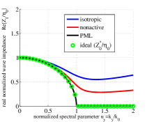
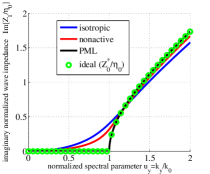
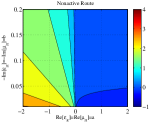
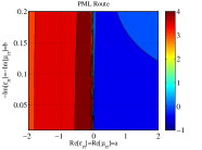
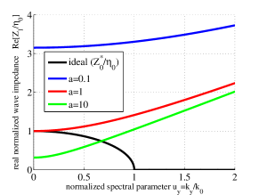
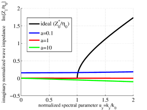
In Figs. 3 we show the variation of the real (Fig. 3) and imaginary (Fig. 3) parts of the normalized wave impedance (12) as functions of for materials with the parameters approximating the ideal values of the CML layer. We examine three possible routes towards CML: (i) An isotropic DNG material with , which has the CML properties in the limit ; this approach is labeled as the “isotropic route”. (ii) A lossy uniaxial double-negative material with the lossless normal component of the permittivity, satisfying , which formally has the ideal CML properties in the limit ; this approach is labeled as the “nonactive route”. Finally, (iii) a double-negative lossy CML medium with ; this approach is labeled as the “PML route”. The impedances are compared with the ideal complex conjugate wave impedance of free space: The equality of the two quantities guarantees maximal absorption.
It is clear that the choice of negative real parts for is successful in terms of ensuring the desired sign of ; one should take into account that for the usual PML with positive real constituent parameters (double-positive, DPS), we obtain for all real and thus , as seen in Fig. 2. It is also apparent that for both real and imaginary parts, the uniaxial material with lossless performs better than the isotropic material. Most importantly, the double-negative lossy CML corresponds to exact conjugate matching, the fact that verifies our initial assumption. Note that such a selection of a “PML” with and changes (compared to the normal DPS PML) only the wave impedance of evanescent modes since is purely real along the propagating spectrum.
One can say that we misapply the concept of PML since the choice of double-negative components inflicts strong reflections for the evanescent modes, namely for , contrary to the usual reflectionless matching property of DPS PML . However, within our paradigm, all propagating waves are fully absorbed, and evanescent fields, in the limit of ideal conjugate matching, generate infinitely strong fields in the medium and deliver infinite power to the absorber in the limit of [Eq. (2)], in the assumption that the illuminating antennas are fed by ideal voltage or current sources capable to supply unlimited power.
III Infinite Planar Configuration
III.1 Incident Field and Absorbed Power
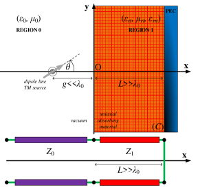
To test and demonstrate the absorbing efficiency of double-negative conjugate matched layers, we consider the planar structure depicted in Fig. 4. A grounded slab of thickness (region 1) filled with a uniaxial medium is excited by an electric dipole line source DipoleLineSource located at the point in the vacuum region (region 0). The dipole moment per unit length of the line is denoted as . The dipoles form an angle with the horizontal axis . The distance between the slab and the source is much smaller than the free-space wavelength (in order for the evanescent waves not to vanish before reaching the sample), and is denoted by . To study absorption of evanescent fields, we choose such a source since its evanescent spectral components are much more pronounced compared to that of more typical cylindrical wave sources such as lines of electric or magnetic currents. Evanes The problem is effectively two-dimensional (2D), due to -independence, and the magnetic field has a single component.
We write the solutions in spectral domain, as a plane-wave decomposition in the form . The expression (33) of the Fourier-transformed incident magnetic field obtained in Appendix can be evaluated at as follows:
| (14) |
where . This field excites the uniaxial slab located at . We note that identical plane-wave field components are generated by sheets of surface electric current placed right in front of the grounded slab. Therefore, the excitation of the slab by the line of electric dipoles (Fig. 4, top) can be equivalently represented by the transmission-line model shown at the bottom of Fig. 4, with the external current source inserted at . Using this circuit model, the power delivered to the slab by each incident spatial harmonic is straightforwardly calculated as:
| (15) |
As above, by we denote the free-space wave impedance, and is the input impedance of the metal-backed uniaxial slab evaluated from the corresponding transmission-line model as Finally, the total power absorbed in the slab is found by integration over all the wavenumber spectrum:
| (16) |
Here it is denoted (for propagating waves, , and for evanescent waves, ).
III.2 Important Limiting Cases
Let us now consider some limiting cases under the simplifying assumption of a half space emulating an electrically thick absorbing slab (valid when , where ). In this case, the input impedance of the metal-backed uniaxial slab approaches its wave impedance: . In our study, the material parameters of the uniaxial layer are chosen so that the conjugate matching condition is closely approached: . When (propagating waves), is purely real and, thus, . Therefore, the power delivered by the propagating modes to the conjugate-matched layer can be calculated as:
| (17) |
Note that this result is independent of the angle because (17) is nothing more than of the total power emitted by a line of dipoles in unbounded free space. This power also equals the total amount of power absorbed by an ideal PML layer (or, equivalently, by a perfect black body) in the structure shown in Fig. 4.
When (evanescent waves), is purely imaginary and, thus, fulfilling the conjugate matching condition results also in almost purely imaginary : . In this case, the denominator of (16) approaches zero. Therefore, in order to analyze this limiting case we must consider a particular model for the material parameters of the uniaxial layer. Here we select the PML route with and , where real is such that . Performing the Taylor expansion with respect to small under the aforementioned assumption and keeping only the first-order term, we obtain the following approximation for :
| (18) |
Separating the real and imaginary parts and taking into account that , we come to the following formula:
| (19) |
Now, we can substitute (19) into (16) and calculate the integral over the evanescent part of the spectrum (). This calculation results in the following approximate expression for the power absorbed from the evanescent modes:
| (20) |
In the denominator of the integrand of (20) we have dropped the term proportional to , because in the DNG case it is multiplied by and in this case the first nonvanishing term is the second-order term in [this term is present in (20)], while in the DPS case the main term is . Equation (20) demonstrates the dramatic influence of the sign of the real part of . In particular, for the CML case when is negative, the denominator of (20) is approximately proportional to , and the following formula results from (20):
| (21) |
where a change of the integration variable has been made. We notice that the absorbed power is proportional to , which means that for small we have huge magnitudes either of absorbed or emitted powers. Such a limiting regime is explained by the singularity of (2) for .
Expression (20) can be applied also for the nonactive route when . Indeed, when , the imaginary part of vanishes and the normal component of the permittivity dyadic acquires the value . Respectively, Eq. (20) becomes
| (22) |
In this case, the absorbed power increases with the decrease of and the increase of .
On the other hand, for the conventional DPS PML case, expression (20) takes the following form:
| (23) |
In this case, when (approaching the ideal impedance matching condition), the relative power delivered to the slab by the evanescent waves tends to zero. This result confirms that within the know PML scenario, the goal of full absorption of propagating waves is incompatible with the goal of extraction power from evanescent fields.
Note that the above approximate formula makes sense only when , because only in this case the integral (23) converges. The divergence of the integral (23) at any other values of is an artifact of the Taylor expansion approximation (18). This approximation is not applicable when approaches (i.e., when ). However, direct evaluation of the integrand in (20) shows no singularity at , even when . Therefore, when , the lower limit of the integration in Eq. (23) must be replaced by , because at this point the first term of the Taylor expansion (18) is about unity: . In this case, Eq. (23) qualitatively agrees with the accurate result (16) (when only the contribution of the domain is considered), with the dominant contribution to the integral coming from a narrow region in the vicinity of the lower limit. Therefore, when and ,
| (24) |
i.e., the power delivered by the evanescent modes in this case is roughly proportional to and also vanishes when .
III.3 Performance of the Proposed Structure
Here we characterize the proposed conjugate matched layers qualitatively, studying the ratio of the total absorbed power and the power which can be harvested only from the propagating part of the spatial spectrum of the excitation in the layer of the infinite thickness (17). Basically, this normalized parameter is the ratio of the power absorbed by our structures and the power absorbed in the classical ideal black body at the same position and excited by the same source. In particular, the output quantity is the logarithm (base 10) of this ratio since we are expecting huge magnitude variations of , as discussed in the previous section.
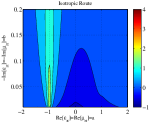
In Figs. 5 we represent the absorption enhancement parameter on the complex permittivity map with for the three considered routes. In the isotropic scenario (Fig. 5), the overall absorption is small while a local maximum is exhibited along the line , which corresponds to the Veselago material VeselagoMaterial . This result is expected, because in the absence of losses this medium is conjugate matched for all modes at this single point DNG ; modeboo . As far as the nonactive route (Fig. 5) is concerned, we observe much better performance compared to the isotropic route: the power extracted from the source is large in a wide range of material parameters, and it is monotonically growing when increases along the negative semi-axis (). Most importantly, in Fig. 5, where the PML case is examined, we clearly notice a huge change in the absorbed power from double-positive to double-negative cases, as expected from (20). In fact, extremely high enhancement of absorption is achieved for the CML case () which means that the structure is sucking all the power (for every single mode, propagated or evanescent) from the source.
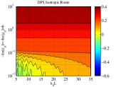
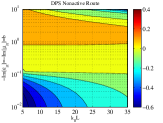
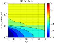
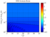
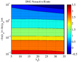
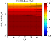
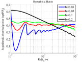
In Figs. 6 and 7 we show the variation of with respect to the electrical thickness of the grounded slab and the loss factors of its relative constituent parameters for the three routes (isotropic, nonactive, and lossy PML) for different signs of (Figs. 6 for and Figs. 7 for ). In the isotropic scenario of the double-positive case (Fig. 6), we observe resonances when is moderate and the reflected fields from are quite strong to interfere with the incident waves, while the absorption is positively related to the loss parameter . When it comes to the DPS nonactive scenario (Fig. 6), we have very small absorption for (as physically anticipated), but there is an optimal range of , for each fixed across which the absorbed power gets maximized. It is also remarkable that the DPS PML configuration (Fig. 6) performs worse than the other two in terms of absorption; furthermore, note that is not substantially dependent on losses , as is clear from (23), (24). As far as the double-negative configurations are concerned, we remark that the behavior of the structure following the isotropic route (Fig. 7) is similar to that of the corresponding double-positive configuration (Fig. 6). On the contrary, the nonactive realization (Fig. 7) does well for small losses and its absorbing efficiency deteriorates with increasing . Finally, the CML structure (Fig. 7) absorbs, on the average, extremely high power , as predicted by (21), and the harvested power is practically not fluctuating with the electrical thickness , because the evanescent mode absorption is due to resonant surface modes.
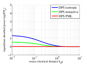
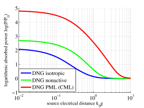
In Figs. 8 we represent the logarithm of the relative absorbed power with respect to the electrical distance from the source to the boundary . All the three scenarios are considered for double-positive (Fig. 8) and double-negative (Fig. 8) configurations. One can notice that the DPS PML absorbs power only from propagating waves since and , as suggested by (23), (24); in other words, PML is outperformed by the other two scenarios in the double-positive paradigm. Again, we remark a similar response of the isotropic structure, regardless of the source location (the blue curves in the two figures), while the nonactive configuration performs always in-between the other two scenarios (which are switching positions when changing the sign of ). In Fig. 8 we observe huge absorption for the DNG CML case at moderate distances to the source (), as expected from (21). Finally, when , according to all the scenarios, the device tends to absorb power which indicates that only propagating waves survive and excite the boundary. The magnitude is the same since, due to the position of the source (), the illumination is almost normally incident on the grounded slab and only the transversal relative parameters (the same for all the scenarios, ) are activated.
To conclude this section we note that although we have considered only one (TM) polarization, all the results are general and hold also for the TE polarization, which can be studied in the same way.
III.4 Comparison with Hyperbolic Media
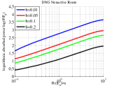
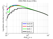
Probably the only known alternative approach to enhance absorption of evanescent fields in large lossy bodies is the use of hyperbolic media hyperbolic_review ; HyperbolicBlackbody ; MetamaterialSpontaneousEmission ; hyp_shalaev ; DipoleLineSource . Due to the transformation of evanescent waves to propagating ones in hyperbolic media, substantial absorption enhancement has been observed MetamaterialSpontaneousEmission ; hyp_shalaev . Therefore, it would be meaningful to compare our results with those obtained when utilizing hyperbolic materials. In hyperbolic media, the real parts of different eigenvalues of the permittivity tensor have opposite signs. Thus, we consider the same structure of Fig. 4 with , and for and small . We assume that , because the maximal absorption is achieved under this assumption HyperbolicBlackbody . In Figs. 9 we present the relative wave impedance (the real and imaginary parts) of the hyperbolic material as functions of the normalized spectral parameter for several . It is apparent that along the entire axis, the differences from the ideal are substantial, which means that the absorption would be dramatically smaller than in our conjugate-matching scenarios. This expectation is confirmed by the results shown in Figs. 10, where the logarithm of the absorbed power is presented as a function of the real part of the permittivity for various loss factors . In the hyperbolic scenario (Fig. 10), the power absorption is, on the average, two orders of magnitude smaller as compared to the absorbed power along the DNG nonactive (Fig. 10) or the PML (Fig. 10) routes. Furthermore, one can point out that for large ( for Figs. 10 and 10) the nonactive route gives better outcomes than the PML route. This property follows from the fact that we have assumed a constant additional loss factor for the PML route. In particular, for , the normal permittivity component of the nonactive material tends to zero (which is the ideal value in the PML route case, corresponding to conjugate matching), but for the PML route, we have . In other words, when is increasing without limit while and remain fixed, the CML response to evanescent excitations appears more lossy than the response of our nonactive device.
IV Finite Cylindrical Configuration
IV.1 Conjugate Matched Cylinder via Coordinate Transformation
Let us next study possibilities for the use of the double-negative conjugate matched materials to create ideal absorbing bodies of finite sizes (in cross sections normal to ). In contrast to an infinite planar surface, studied above, finite-sized bodies can in principle absorb infinite power carried by a single propagating plane wave, generated by sources at infinity Bobr ; unlimited_antenna ; SphericalPaper . A conceptual example of a spherical body having these properties has been described SphericalPaper , where the sphere was filled with a locally isotropic low-loss double-negative material. As discussed above, double-negative materials can be ideally conjugate matched to free space, but only in the limit of negligible loss factors. Here we study a cylindrical configuration and explore additional design possibilities offered by double-negative perfectly matched layers, which have more free parameters to tune.
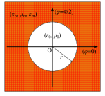
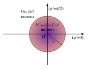
With the goal of finding the material parameters of a cylindrical CML, we adopt an already proposed approach SphericalPaper and consider first a complementary infinitely long cylindrical shell filling the space from to (see Fig. 11, where the used cylindrical coordinate system is also defined). We first assume that the shell is filled with a medium characterized by the following, more general (compared to the PML case) permittivity and permeability dyadics in cylindrical coordinates: [.
In order to obtain the corresponding material parameters for a cylinder with a finite radius , we map the outer space of the cylindrical volume into the internal vacuum hole and vice versa, as shown in Fig. 11. This mapping can be done using the concept of transformation optics Milton ; TransformationOptics , and it has been already performed in the analogous case of isotropic media and the spherical shape of the conjugate matched body SphericalPaper . More specifically, we can use the following coordinate transformation from the unprimed to the primed coordinates:
| (25) |
where can be any positive real number. Note that the sign of the -component changes in the transformation. As is inversely proportional to , the corresponding coordinate axes have opposite directions. Therefore, in order to map a right-handed coordinate system to a right-handed coordinate system, we also change the direction of either the or axes.
The material parameters transform according to the well-known coordinate transformation equations TransformationOptics :
| (26) |
where denotes the transpose of a matrix, and are the original material parameter matrices (i.e., the material parameters of the infinite mantle at ), and are the transformed material parameter matrices (i.e., the material parameters of the finite core, ), and A is the Jacobian matrix of the transformation. The Jacobian matrix in this particular case of (25) is given by:
| (27) |
By inserting the above expressions into (26), the transformed relative material parameters for the core can be written in cylindrical coordinates as:
| (28) |
Furthermore, if we assume that the initial cylindrical shell has PML characteristics, that is, its relative constituent parameters are defined as (still assuming ]), we can write the transformed parameters as
| (29) |
It should be noted that we can derive the same material parameters if we, alternatively, demand instead of in the initial coordinate transformation. At this stage we are free to choose any real values for and any positive value for ; however, in this study we limit the analysis to the case . Furthermore, we confine ourselves to the TM case with no harm to generality.
As we did in the case of an infinite planar slab, we consider three different routes approaching the ideal conjugate matched cylinder, namely the isotropic, nonactive and PML routes. Here, the isotropic route corresponds to isotropic shell parameters, that is, . Clearly, according to (28) this corresponds to transformed parameters that are not isotropic. However, we will use the term “isotropic” also in this case to maintain harmony of the terminology with the planar slab example. In the nonactive scenario, as before for the planar case, the normal (radial) permittivity and permeability are assumed to be real while the other material parameters are given by (29). In the PML route, we again assume that the normal components of permittivity and permeability are slightly more lossy than it is dictated by the ideal PML rule (given in (29)) in order to avoid possible numerical instabilities owed to the limiting nature of the ideal CML .
IV.2 Performance of the Proposed Structure
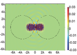
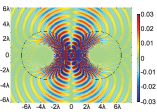
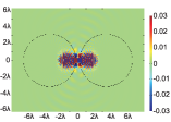
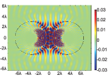
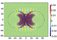
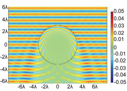
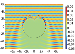
In Figs. 12 and 13, we consider the case of two cylinders having material parameters corresponding to the three routes described in the previous subsection (“isotropic”, nonactive, and PML routes) and depicted in Fig. 11. We position the source line symmetrically in-between two cylinders of radius which are separated by distance . When the source is that depicted in Fig. 4, namely a TM dipole line source, we again choose for maximal excitation of the system. In Figs. 12–12 we consider the DPS (PML) cases with , while in Figs. 13–13 the DNG (CML) ones with . By inspection of the contours, one directly infers that the DNG approach is much more efficient in terms of absorption: in the DNG case, practically all the power created by the source is absorbed by the cylinders. On the contrary, in all the DPS cases a considerable amount of power propagates away from the cylinders. Similar effect was observed for the DNG cylinders even if the dipole line excitation was replaced by a -directed current line, despite the fact that the incident field is nonzero along the axis. The difference between Figs. 12, 12 and between Figs. 13,13 is negligible due to small losses combined with the choice of fairly large . Figs. 13,13 show that surface plasmon modes are strongly excited due to smaller overall losses compared to the other cases. In the nonactive and PML routes with shown in Figs. 13 and 13, surface plasmon modes are strongly excited on the surface of the cylinders which does not happen for the isotropic DNG case shown in Fig. 13 due to higher losses in the radial material parameters compared to the other cases.
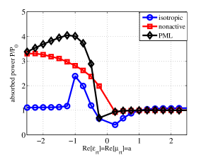
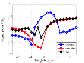
In Fig. 14 we show the variations of the absorbed power normalized by , which corresponds to the absorbed power in the DPS-PML case with , with respect to . Given the fact that the conventional PML absorbs only propagating waves, the physical meaning of is identical to the corresponding one of the planar slab cases. Regardless of the considered route (isotropic, nonactive, PML), there is a substantial switch in absorption efficiency from (DNG case) to (DPS case): the absorbed power is always much higher for . For positive values of , all routes lead to similar results. The higher absorption in the isotropic shell case is simply due to the lossy radial component (as opposed to nonactive/active used in the other two cases). When it comes to the isotropic shell case, the maximal absorption is achieved when , since the power drops quickly as deviates from in either direction; similar behavior has been observed also for the planar slab case, as well as for the double-negative sphere SphericalPaper . It should be noted that at practically the only difference between the material parameters given by the three scenarios are the losses in the radial permittivity and permeability. Furthermore, it should be stressed that in the nonactive DNG case, the maximum absorbed power (exhibited at ) is smaller than in the PML scenario but larger than in the isotropic shell case, as could be expected. Similarly to the planar case, the highest is recorded for the PML route. In Fig. 14 we present the escaped power with respect to the real part of the transversal relative permittivity . denotes the power carried away by the surviving fields at . The values of for are greatly diminished compared to the DPS cases, a feature that demonstrates the higher absorption effectiveness of the DNG structures. For , the escaped power is the smallest for the isotropic scenario which is, again, due to higher losses compared to the other cases.
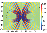
Finally, in Figs. 15 we examine absorption effectiveness of double-negative conjugate matched cylinders illuminated by a single propagating plane wave. According to the results of Ref. SphericalPaper, , in the limiting case of the ideal CML, the effective absorption width can be arbitrarily large, although the sources of illumination are infinitely far from the cylinder. We consider only the PML route for (DPS, Fig. 15) and (DNG, Fig. 15). Note that in both cases, there are practically no reflections from the cylinder and a huge shadow is formed behind. Furthermore, resonant plasmonic modes are excited on the surface of the cylinder in the DNG case, which increases the shadow due to stronger field coupling. Although the excitation is a single propagating plane wave, coupling to predominantly evanescent resonant modes of the absorbing cylinder is possible because the surface is curved. In this particular example, the power absorbed by the cylinder is about higher in the DNG case compared to the DPS case (the latter case corresponds to the ideal black body as defined in Ref.GK ). In other words, even in the absence of incident evanescent plane-wave modes we can achieve improved absorption using DNG cylinders as compared to the perfectly non-reflecting DPS cylinder, thanks to the aforementioned activation of resonant surface plasmon modes. However, for the same material parameters, the effect is quite modest compared to the increased power absorption when evanescent wave modes are strongly present in the spatial spectrum of the source.
V Practical Realization of the CML Concept
As is clear from the above results, two scenarios are promising for realizations of the proposed conjugate matched bodies: the nonactive route and the PML route. In the nonactive route, the required material parameters correspond to well-studied uniaxial double-negative (backward-wave) metamaterials MetaReview . A wide variety of micro- and nanostructures which realize double-negative response in different frequency ranges have been proposed and studied in the literature. For the new application proposed here, the materials should have a controllable degree of anisotropy: in particular, the case when the absolute values of the tangential components are much larger than those of the normal components is of interest. With this in view, one of the most promising topologies is the so-call fishnet structure FishnetMetamaterials ; MetaReview ; SlabWire ; PolarizationIndependent . This is a multilayer structure where thin metal sheets with periodically positioned holes (usually of the square or round shape) are separated by dielectric spacers.
While the response in the tangential plane is strongly modified by large induced currents flowing along the metal sheets, the response to fields along the normal direction is modified only due to quasi-static electric polarization of thin sheets. In the microwave domain, the normal components of the material parameters usually have positive real parts. To achieve the necessary negative permittivity value of the normal component, it is possible to insert an array of thin metal wires passing through the holes in the fishnet layers. If the wires are made of a good conductor, the microwave response will correspond to a negative and nearly real value of the normal component of the permittivity tensor, exactly as required for the CML realization.
At infrared and optical frequencies, it is possible to exploit the negative permittivity of metals from which the fishnet layers can be fabricated. In this case, metal wires are not needed, and the values of the normal component of the permittivity can be controlled by choosing the thickness ratio of the metal and dielectric layers in the fishnet structure. In particular, if rectangular holes are etched in a layer of Magnesium fluoride (MgF2) sandwiched between silver slabs, one can achieve negative refractive index SilverMagnesiumFluoride at the optical frequencies under the necessary homogenization conditions OurFishnet . Furthermore, nonlinearity of liquid crystals can be exploited in order to develop tunable fishnets metamaterials whose reflection/transmission (and accordingly their effective ) is externally controlled. More generally speaking, it is well known that if we insert metallic particles such as cylindrical pins, strips, spirals or flakes, which are having negative permittivity in the visible spectrum MetallicNegativePermittivity , we can EffectiveFormula obtain materials with .
The conclusion that the performance of nonactive-route CML improves when the absolute value of the real part of the tangential permittivity increases (Section III) is very important for choosing practically realizable material parameters. As was discussed above, high absorption of energy from evanescent fields requires that the overall losses in the medium are small (this is in fact clear already from eq. (2)). Realization of passive low-loss DNG metamaterials is a challenge, although some successful approaches are known, e.g. PMMLossesA . However, for the nonactive PML with large magnitudes of negative , high absorption is observed even when the imaginary part of the tangential permittivity is not very small and corresponds to practically realizable structures. The normal component of the permittivity in this case corresponds to epsilon-near-zero materials, which are also known to be practically realizable Liisi ; Engheta_ENZ .
The required overall small level of losses can achieved also using active (pumped) structures. This can be done by using active parts such as optically pumped laser dyes to balance the losses of the background structure PMMLossesB . In this way, one can realize an effective DNG medium possessing additional negative normal components () with controllable loss factors of the tangential components: . Active control of the normal permittivity and permeability components can be used to implement also the active PML route towards CML. Based on the fishnet-wire medium approach described above, instead of metallic rods or spirals one can insert nano-generators ActivePMMA or pumps ActivePMMB into the holes of the background structure which can provide energy to the system and make the normal component of the effective parameters active.
VI Conclusions
In this paper, we have introduced the concept of double-negative conjugate matched layer (CML), which has the property of acting as the ideal sink for energy of electromagnetic fields. Arbitrary propagating waves illuminating such layer produce no reflections and are fully absorbed in the medium. Evanescent fields, existing in the vicinity of small sources or scatterers, induce very strong resonant fields, oscillating in the vicinity of the CML surface. The energy stored in the reactive evanescent modes sinks into the layer and is transformed into heat or delivered to loads in its constitutive elements.
There is an analogy of this phenomenon and the circuit-theory concept of the ideal voltage or current source. An ideal voltage source delivers infinite power to the load in the limit of infinitely small resistive load [eq. (2)], because the current through a resistor tends to infinity when the resistance tends to zero. Likewise, for every evanescent mode the sum of the wave impedances of fields in free space and that in the CML is real and can be made very small. Thus, the layer dramatically enhances the near fields created by given sources and sacks their energy into the material layer. This phenomenon can be compared also with the Purcell effect of enhancement of spontaneous emission rate of small sources due to the presence of resonant and efficiently radiating bodies in the vicinity of the source Nov ; Alu_Eng . However, resonant cavities or antennas used to enhance radiation from a small emitter work only at one or a few resonant modes of the resonator. The introduced CML concept brings the Purcell effect to the limit of extracting all available energy from a small source. In this paradigm, every mode of the source field resonates with a corresponding mode of the CML, so that the complete system of the source and the absorbing body is tuned for the optimal power extraction from all modes of the fields created by the source.
Although the ideal double-negative conjugate matched layer requires active inclusions for its practical realization PML_active (the normal components of the material parameters have the imaginary parts corresponding to active media), the flexibility of the CML concept suggests a more practical possibility for realizations, where only passive materials are used: the nonactive route, described in this paper, requires double-negative lossy values of the tangential components and low-loss negative values of the normal components of the permittivity and permeability matrices. The results of extensive studies of various possibilities to design and realize double-negative (backward-wave) materials can be used to realize the proposed structures. While the earlier introduced isotropic double-negative design SphericalPaper requires very small levels of losses, which are probably not possible to achieve in practice, at least with the use of only passive materials, the radially uniaxial double-negative structure proposed here appears to offer possibilities to overcome this limitation. We hope that the results of this study will have interesting and important implications for a wide variety of applications: in light harvesting, thermal emission control, heating and cooling devices, stealth, decoupling of radiators, receiving and transmitting antennas, and other microwave and optical devices.
Acknowledgements.
S. I. Maslovski acknowledges financial support under “Investigador FCT (2012)” grant.*
Appendix A Expression for the Incident Field Created by the Dipole Line
In the spectral domain, the free-space vector potential created by the line of dipoles shown in Fig. 4 can be written for this 2D problem as
| (30) |
where is the electric dipole moment linear density. Taking the inverse Fourier transform with respect to we obtain
| (31) |
where . When , (31) reduces to the well-known expression for the vector potential of a uniform electric dipole moment sheet. The magnetic field of the same line of dipoles is found using:
| (32) |
where (recall that there is no dependence on ). The result reads
| (33) |
where . Because the vector lies in the plane, the incident magnetic field has just a single component along the axis, i.e., the incident waves are TM-polarized plane waves.
References
- (1) G. Kirchhoff, “On the relation between the radiating and absorbing powers of different bodies for light and heat”, Philosophical Magazine, vol. 4, pp. 1-21, 1860.
- (2) Y. Radi, C. R. Simovski, and S. A. Tretyakov, “Thin perfect absorbers for electromagnetic waves: Theory, design, and realizations”, Physical Review Applied, vol. 3, no. 037001, 2015.
- (3) C. M. Watts, X. Liu, and W. J. Padilla, “Metamaterial electromagnetic wave absorbers”, Advanced Materials vol. 24, OP98, 2012.
- (4) E. E. Narimanov and A. V. Kildishev, “Optical black hole: Broadband omnidirectional light absorber”, Applied Physics Letters, vol. 95, no. 041106, 2009.
- (5) A. V. Kildishev, L. J. Prokopeva, and E. E. Narimanov, “Cylinder light concentrator and absorber: theoretical description”, Optics Express, vol. 18, no. 16, pp. 16646–16662, 2010.
- (6) Q. Cheng, T. J. Cui, W. X. Jiang, and B. G. Cai, “An omnidirectional electromagnetic absorber made of metamaterials”, New Journal of Physics, vol. 12, no. 063006, 2010.
- (7) J.-P. Berenger, “A perfectly matched layer for the absorption of electromagnetic waves”, Journal of Computational Physics, vol. 114, pp. 185-200, 1994.
- (8) S.D. Gedney, “An anisotropic perfectly matched layer – absorbing medium for the truncation of FDTD lattices”, IEEE Transactions Antennas and Propagation, vol. 44, no. 12, pp. 1630-1639, 1996.
- (9) R.W. Ziolkowski, “The design of Maxwellian absorbers for numerical boundary conditions and for practical applications using engineered artificial materials”, IEEE Transactions Antennas and Propagation, vol. 45, no. 4, pp. 656-671, 1997.
- (10) S.A. Tretyakov, T.G. Kharina, “The perfectly matched layer as a synthetic material with active inclusions”, Electromagnetics, vol. 20, no. 2, pp. 155-166, 2000.
- (11) A. Poddubny, I. Iorsh, P. Belov, and Y. Kivshar, “Hyperbolic metamaterials”. Nature Photonics, vol. 7, pp. 948-957, 2013.
- (12) L. B. Felsen and N. Marcuvitz, Radiation and Scattering of Waves, IEEE Series on Electromagnetic Wave Theory, John Wiley & Sons, New Jersey, 1972.
- (13) S.-A. Biehs and M. Tschikin and P. Ben-Abdallah, “Hyperbolic metamaterials as an analog of a blackbody in the near field”, Physical Review Letters, vol. 109, no. 104301, 2012.
- (14) M. A. Noginov, H. Li, Y. A. Barnakov, D. Dryden, G. Nataraj, G. Zhu, C. E. Bonner, M. Mayy, Z. Jacob and E. E. Narimanov, “Controlling spontaneous emission with metamaterials”, Optics Letters, vol. 35, pp. 1863-1865, 2010.
- (15) Z. Jacob, J.-Y. Kim, G. V. Naik, A. Boltasseva, E. E. Narimanov, and V. M. Shalaev, “Engineering photonic density of states using metamaterials”, Applied Physics B vol 100, pp. 215ֲ18, 2010.
- (16) I. S. Nefedov, C. A. Valagiannopoulos, S. M. Hashemi, and E. I. Nefedov, “Total absorption in asymmetric hyperbolic media”, Scientific Reports, vol. 3, no. 2662, 2103.
- (17) Yu. I. Bobrovnitskii, “ Impedance theory of sound absorption: The best absorber and the black body”, Acoustical Physics, 2006, vol. 52, no. 6, pp. 638–647, 2006 (Original Russian Text: Akusticheski Zhurnal, vol. 52, no. 6, pp. 742–752, 2006).
- (18) D.-H. Kwon and D. M. Pozar, “Optimal characteristics of an arbitrary receive antenna”, IEEE Trans. Antennas Propag. vol. 57, 3720, 2009.
- (19) S. I. Maslovski, C. R. Simovski, S. A. Tretyakov, “Overcoming black body radiation limit in free space: metamaterial ’thermal black hole”’, arXiv:1412.4625 [physics.optics], 2014.
- (20) D. Polder and M. van Hove, “Theory of radiative heat transfer between closely spaced bodies”, Physical Review B, vol. 4, no. 3303, 1971.
- (21) J. B. Pendry, “Radiative exchange of heat between nanostructures”, Journal of Physics: Condensed Matter, vol. 11, pp. 6621ֶ633, 1999.
- (22) A.I. Volokitin and B.N.J. Persson, “Resonant photon tunneling enhancement of the radiative heat transfer”, Physical Review B, vol. 63, no. 045417, 2004.
- (23) K. Joulain, J.-P. Mulet, F. Marquier, R. Carminati, and J.-J. Greffet, “Surface electromagnetic waves thermally excited: Radiative heat transfer, coherence properties and Casimir forces revisited in the near field”, Surface Science Reports, vol. 57, pp. 59-112, 2005.
- (24) D. M. Pozar, Microwave Engineering, John Wiley & Sons, New York, 2012 (pp. 48).
- (25) C. Simovski, S. Maslovski, I. Nefedov, and S. Tretyakov, “Optimization of radiative heat transfer in hyperbolic metamaterials for thermophotovoltaic applications”, Optics Express, vol. 21, pp. 14989-15013, 2013.
- (26) S. Tretyakov, Analytical Modeling in Applied Electromagnetics, Artech House, Norwood, Massachusetts, 2003.
- (27) J. Pendry, “Negative refraction makes a perfect lens”, Physical Review Letters, vol. 85, pp. 3966-3969, 2000.
- (28) C. A. Valagiannopoulos, M. S. Mirmoosa, I. S. Nefedov, S. A. Tretyakov and C. R. Simovski, “Hyperbolic-metamaterial antennas for broadband enhancement of dipole emission to free space”, Journal of Applied Physics, vol. 116, no. 163106, 2014.
- (29) V. G. Veselago and E. E. Narimanov, “The left hand of brightness: past, present and future of negative index materials”, Nature Materials, vol. 5, pp. 759-762, 2006.
- (30) G. W. Milton, M. Briane, and J. R. Willis, “On cloaking for elasticity and physical equations with a transformation invariant form”, New Journal of Physics, vol. 248, pp. 1-20, 2006.
- (31) D.-H. Kwon and D. H. Werner, “Transformation electromagnetics: an overview of the theory and applications”, IEEE Antennas and Propagation Magazine, vol. 52, pp. 25-46, 2010.
- (32) N. I. Zheludev and Y. S. Kivshar, “From metamaterials to metadevices”, Nature Materials, vol. 11, pp. 917-924, 2012.
- (33) J. Valentine, S. Zhang, T. Zentgraf, E. Ulin-Avila, D. A. Genov, G. Bartal, and X. Zhang, “Three-dimensional optical metamaterial with a negative refractive index”, Nature, vol. 455, pp. 376-380, 2008.
- (34) M. Kafesaki, I. Tsiapa, N. Katsarakis, Th. Koschny, C. M. Soukoulis, and E. N. Economou, “Left-handed metamaterials: the fishnet structure and its variations”, Physical Review B, vol. 75, no. 235114, 2007.
- (35) K. B. Alici and E. Ozbay, “A planar metamaterial: Polarization independent fishnet structure”, Photonics and Nanostructures: Fundamentals and Applications, vol. 6, pp. 102-107, 2008.
- (36) J. Yang, C. Sauvan, H. T. Liu, and P. Lalanne, “Theory of fishnet negative-index optical metamaterials”, Physical Review Letters, vol. 107, no. 043903, 2011.
- (37) C. Menzel, T. Paul, C. Rockstuhl, T. Pertsch, S. Tretyakov, and F. Lederer, “Validity of effective material parameters for optical fishnet metamaterials”, Physical Review B, vol. 81, no. 035320, 2010.
- (38) E. D. Palik, Handbook of Optical Constants of Solids, Academic, New York, 1985.
- (39) C. A. Valagiannopoulos and S. A. Tretyakov, “Emulating hyperbolic-media properties with conventional structures”, New Journal of Physics, vol. 455, pp. 376-380, 2008.
- (40) J. Valentine, S. Zhang, T. Zentgraf, and X. Zhang, “Development of bulk optical negative index fishnet metamaterials: achieving a low loss and broadband response through coupling”, Proceedings of the IEEE, vol. 99, pp. 1682-1690, 2011.
- (41) S. Tretyakov, A. Sihvola, L. Jylhä, “Backward-wave regime and negative refraction in chiral composites”, Photonics and Nanostructures - Fundamentals and Applications, vol. 3, no. 2-3, pp. 107-115, 2005.
- (42) R. Maas, J. Parsons, N. Engheta, and A. Polman, “Experimental realization of an epsilon-near-zero metamaterial at visible wavelengths”, Nature Photonics, vol. 7, pp. 907ֹ12, 2013.
- (43) S. Wuestner, A. Pusch, K. L. Tsakmakidis, J. M. Hamm, and O. Hess, “Overcoming losses with gain in a negative refractive index metamaterial”, Physical Review Letters, vol. 105, no. 127401, 2010.
- (44) T. Jiang, K. Chang, L.-M. Si, L. Ran, and H. Xin, “Active microwave negative-index metamaterial transmission line with gain”, Physical Review Letters, vol. 107, no. 205503, 2011.
- (45) S. Anantha Ramakrishna and J. B. Pendry, “Removal of absorption and increase in resolution in a near-field lens via optical gain”, Physical Review B, vol. 67, no. 201101, 2003.
- (46) L. Novotny, B. Hecht, Principles of Nano-Optics, Cambridge University Press, Cambridge, UK, 2012 (section 8.4).
- (47) A. Alu and N. Engheta, “Boosting molecular fluorescence with a plasmonic nanolauncher”, Physical Review Letters, vol. 103, no. 043902, 2009.