Current address: ]Department of Physics, University of Texas at Austin, Austin, TX 78712, USA Current address: ]Honeywell International, Golden Valley, MN 55422, USA
Modulating carrier and sideband coupling strengths in a standing wave gate beam
Abstract
We control the relative coupling strength of carrier and first order motional sideband interactions of a trapped ion by placing it in a resonant optical standing wave. Our configuration uses the surface of a microfabricated chip trap as a mirror, avoiding technical challenges of in-vacuum optical cavities. Displacing the ion along the standing wave, we show a periodic suppression of the carrier and sideband transitions with the cycles for the two cases out of phase with each other. This technique allows for suppression of off-resonant carrier excitations when addressing the motional sidebands, and has applications in quantum simulation and quantum control. Using the standing wave fringes, we measure the relative ion height as a function of applied electric field, allowing for a precise measurement of ion displacement and, combined with measured micromotion amplitudes, a validation of trap numerical models.
pacs:
03.67.Lx, 32.80.Qk, 37.10.Ty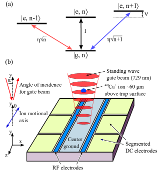
The excitation spectrum of a trapped ion in a radio frequency (RF) trap acquires sidebands due to the harmonic motion of the ion (Fig. 1(a)) Leibrandt et al. (2009). The interaction between an optical field and the the trapped ion leads to an almost ideal Jaynes-Cummings interaction Jaynes and Cummings (1963); Wu and Yang (1997) which couples the internal degrees of freedom to the ion motion and is the basis for two-qubit gates in ion trap quantum computation Cirac and Zoller (1995); Sørensen and Mølmer (2000); Schmidt-Kaler et al. (2003). Sideband interactions are used in trapped ion experiments for a variety of additional functions such as cooling to the motional ground state Diedrich et al. (1989), measurements of the ion heating rate Turchette et al. (2000); Shu et al. (2014), and identifying and cooling molecular ions Goeders et al. (2013); Rugango et al. (2015); Wan et al. (2015). Off-resonant coupling to the carrier transition, either evident as motion independent population transfer or an AC Stark shift, places a limit on the speed of the sideband interactions. Suppressing the carrier can remove this limit and, in particular, would allow for improved two-qubit gate fidelities as the gate time becomes comparable or shorter than a cycle of the harmonic motion Sørensen and Mølmer (2000); Mizrahi et al. (2014).
Suppression of the carrier also has applications in quantum simulation. Trapped ions have been proposed as a system for modeling the expansion of the universe Menicucci et al. (2010). The simulation requires off-resonant excitation of both the red and blue sidebands by a red-detuned exciting field, with no coupling to the carrier. Because the blue sideband is both weaker and further from resonance than the carrier transition, suppression of the carrier is important for such an experiment.
Replacing running wave optical beams with standing wave beams provides a method to selectively suppress the carrier and reduce off-resonant excitations when addressing the motional sidebands Cirac et al. (1992); Zhang et al. (2012). In such a configuration, the coupling strengths of the carrier and sidebands acquire a periodic dependence on the atom’s spatial position within the standing wave fringes Cirac et al. (1992); James (1998), with the cycles for the two cases out of phase with each other. Standing wave beams have also been proposed for use in measuring parity nonconservation effects in trapped ions for this reason Fortson (1993); Koerber et al. (2003). This periodic dependence of the coupling strengths has been demonstrated in cavity experiments with trapped ions Leibrandt et al. (2009); Guthöhrlein et al. (2001); Steiner et al. (2013); Mundt et al. (2002). However, the use of cavities involves technical challenges, in particular when integrating the cavity with microfabricated ion traps where optics and dielectric mirrors can become charged Harlander et al. (2010); Clark et al. (2014).
In this paper, we demonstrate the same position dependence with a single mirror which, in this case, is simply the surface of the ion trap itself (Fig. 1(b)). To handle the case of imperfect beam alignment, reflection losses, and similar system limitations, we extend the calculations of Refs. Cirac et al. (1992); James (1998) to the case of non-normal incidence laser beams and unequal couplings of the incident and reflected laser beams with the ion. We find a criterion for the out of phase carrier and sideband coupling strengths that is set by the incident angle of the laser beam and the orientation of the ion’s harmonic motion.
A trapped ion interacting with an ideal standing wave laser field is treated in Refs. Cirac et al. (1992); James (1998). We extend this treatment to include an angle of incidence relative to the mirror normal (see Fig. 1) and differing couplings of the incident and reflecting beams to the atomic transition. The latter can arise due to imperfect reflectivity of the mirror, differing polarization of the two beams, and, for quadrupole transitions such as used here, the laser beam vector dependence of the coupling. For a harmonically trapped two level atom in the rotating wave approximation, the interaction Hamiltonian (up to a global phase) is
Here, and are the Rabi frequencies of the incident and reflected beams, respectively, ( is the raising (lowering) operator of the two level atom, () is the raising (lowering) operator of the secular motion, is the laser’s detuning from the carrier resonance, and is the secular frequency. The phase represents the optical phase of the standing wave at the atom’s equilbrium position . The Lamb-Dicke parameters and are defined as
where is the angle of the motional mode axis relative to surface normal, is the ion mass, and is the wavenumber of the gate beam. In the Lamb-Dicke approximation, the interaction Hamiltonian can be decomposed into a carrier term
a red sideband term
and a corresponding blue sideband term. Following the treatment in Ref. Roos (2000), these Hamiltonians lead to respective coupling strengths
| (1) |
and
| (2) |
where is the occupation number of the quantized harmonic oscillator. Interference between the terms produce fringes in the coupling strengths as the ion position changes. When , and have opposite sign, and the carrier and sideband fringes are out of phase. When the atom lies on a node of the standing wave, (with an integer) and the carrier coupling strength is maximized while the sideband coupling strengths are minimized. On an anti-node, and the converse is true. These fringes correspond to a physical displacement of the ion by , where is the wavelength of the exciting laser.
Our experimental configuration is depicted schematically in Fig. 1(b). We use a surface electrode linear ion trap to confine and cool 40Ca+ ions, as described in Ref. Doret et al. (2012). The ion is confined 60 m above the trap surface by a combination of RF and DC potentials. We use the quadrupole transition at nm for our measurements. The 729 nm beam reflects off of the aluminum trap surface with a reflectivity of , producing a standing wave field in the direction. The angle due to restrictions in the beam path, which limits the fringe contrast. We tune the laser to address either the carrier transition or the first order red sideband transition of a motional mode with MHz (on the RF null) and (see Fig. 1(b)).
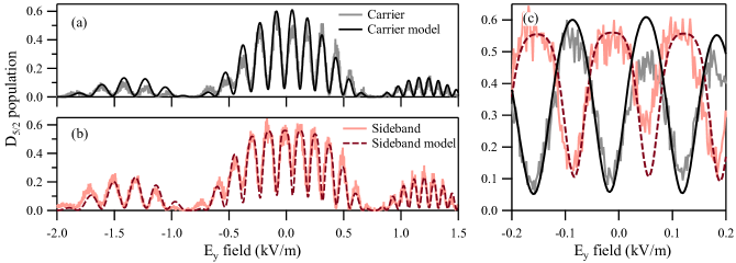
To displace the ion’s equilibrium position along the standing wave, we apply an electric field by adjusting the trap’s DC potentials. The case = 0 corresponds to the ion being on the RF null. For and , the ion is displaced along and , respectively. The range of values used in this experiment displaces the ion over a 10 m range. The fringes in the carrier and sideband transitions resulting from this displacement are evident in Fig. 2.
Displacing the ion from its equilibrium position on the RF null affects the dynamics in several ways beyond the fringing. First, the displacement introduces micromotion Leibfried et al. (2003) that modulates the coupling strengths of both the carrier and sideband Berkeland et al. (1998). To account for this modulation, we multiply equations (1) and (2) by the Bessel function , where is the modulation parameter given by
| (3) |
Here is the wavelength of the gate beam, is the trap RF frequency, and are the mass and charge of the ion, is the RF pseudopotential, and is the angle between the micromotion direction and the gate beam. Our trap has an RF quadrupole that is rotated in the plane relative to the surface normal Doret et al. (2012); during ion displacement, we apply a small proportional to such that at all points. Second, the ion’s motional frequencies change after displacement. We track the changing frequency by measuring the sideband’s resonance for different displacements.
Figs. 2(a) and (b) show state populations measured after driving carrier or sideband transitions as a function of applied field. The population is determined by the electron shelving technique that correlates observation fluorescence with the state of the ion: is bright and is dark. We observe fringes due to the standing wave field superimposed with the envelope due to the micromotion modulation. The maxima (minima) of the carrier fringes correspond to the ion positioned on nodes (anti-nodes) of the standing wave. For a dipole coupling instead of the quadrupole used here, the node/anti-node dependence is reversed. The carrier and sideband fringes are overlaid in Fig. 2(c). The standing wave fringes of the carrier and sideband oscillate 180∘ out of phase with one another, as predicted by equations (1) and (2).
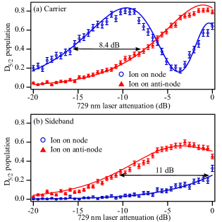
Fig. 3(a) shows that by adjusting the ion’s position in the standing wave laser field, we can achieve an effective suppression of the carrier that is equivalent to an 8 dB reduction in the gate beam power. For the sideband in Fig. 3(b), an equivalent 11 dB reduction can be achieved.
To produce the fits seen in Figs. 2 and 3, we use the excited state population equation for a thermal ion given by
where is the ion’s mean number of motional quanta and is or depending on whether we are fitting carrier or sideband data, respectively Leibfried et al. (2003). The fringes and overall envelope in Fig. 2 arise from the dependence of and on the ion’s displacement . We parameterize with and parameterize , for coefficients and . These coefficients, along with , , , and , form the full set of parameters that define the simultaneous fits of the data in Figs. 2 and 3. In particular, the set has , , and (consistent with the Doppler cooled ion in our configuration).
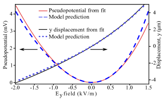
Using equation (3), we can determine the pseudopotential from . Fig. 4 plots the resulting and the ion displacement as a function of . We compare these with the results from a numerical model of the trapping potentials. The model includes a 700 V/m uniform stray field that was adjusted to match the observed RF null in Fig. 2. The magnitude of the RF trapping potential used in the model was adjusted to match the observed mode frequencies at . There are no other free parameters used in the model. The agreement seen provides a measure of confidence in the model and future predictions.
To summarize: we have demonstrated how the carrier and motional sideband transition coupling strengths of a trapped ion may be controlled by displacing the ion within a resonant standing wave field. In our configuration, in which a standing wave is formed by retroreflecting an incident beam off of a surface electrode trap, we achieve suppression of the carrier (sideband) by the equivalent of an 8 dB (11 dB) reduction in the driving beam power. Our experimental results are in good agreement with both theoretical models of the coupling strengths’ behaviors and numerical models of the trapping potentials. The degree of carrier/sideband suppression achievable ultimately depends on the quality of the standing wave field at the ion’s position, which is related to the ratio . The trap’s surface reflectivity limits us here to . We can approach this limit with improved beam alignment, which would allow for a carrier suppression equivalent to a 29 dB reduction in driving beam power when and . Further carrier suppression would require the use of a more reflective surface. For instance, we measure the reflectivity from a gold coated trap like the one described Ref. Guise et al. (2015) to be , which could provide an equivalent carrier suppression of 40 dB. Similar quality standing waves could be generated by incorporating a metallic mirror adjacent to an ion trap if the trap surface is not amenable to this purpose.
Suppression of the carrier implies that the driving laser’s power may be freely increased by an amount equivalent to the effective suppression, allowing for faster sideband interactions with no increased chance of an off-resonant carrier excitation. For the 8 dB effective carrier suppression reported here, sideband interactions could be performed 2.5 times faster; at the 29 dB suppression limit of our aluminum trap, 28 times faster; at the 40 dB suppression limit of a gold coated trap, 100 times faster.
In our current configuration, a 29 dB carrier suppression factor would reach the regime in which simulating the expansion of the universe with trapped ions becomes experimentally feasible, such that the excitation of detectors occurs when cosmic photons are created Menicucci et al. (2010). When the beam has more running wave character, the simulation is dominated by excitation of detectors with photon creation or destruction. Quantum simulations of the expanding universe have also been proposed using Bose-Einstein condensates Fischer and Schützhold (2004) and can be performed in a digital manner with a number of quantum systems Georgescu et al. (2014); Mezzacapo et al. (2014).
Acknowledgements.
This work was supported by the Georgia Tech Research Institute. KRB was supported by the Director of National Intelligence (ODNI), Intelligence Advanced Research Projects Activity (IARPA), under US Army Research Office (ARO) contracts W911NF-10-1-0231. TD would like to thank support by a Georgia Tech President’s Fellowship.References
- Leibrandt et al. (2009) D. R. Leibrandt, J. Labaziewicz, V. Vuletić, and I. L. Chuang, Phys. Rev. Lett. 103, 103001 (2009).
- Jaynes and Cummings (1963) E. Jaynes and F. Cummings, Proc. of the IEEE 51, 89 (1963).
- Wu and Yang (1997) Y. Wu and X. Yang, Phys. Rev. Lett. 78, 3086 (1997).
- Cirac and Zoller (1995) J. I. Cirac and P. Zoller, Phys. Rev. Lett. 74, 4091 (1995).
- Sørensen and Mølmer (2000) A. Sørensen and K. Mølmer, Phys. Rev. A 62, 022311 (2000).
- Schmidt-Kaler et al. (2003) F. Schmidt-Kaler, H. Häffner, M. Riebe, S. Gulde, G. P. Lancaster, T. Deuschle, C. Becher, C. F. Roos, J. Eschner, and R. Blatt, Nature 422, 408 (2003).
- Diedrich et al. (1989) F. Diedrich, J. C. Bergquist, W. M. Itano, and D. J. Wineland, Phys. Rev. Lett. 62, 403 (1989).
- Turchette et al. (2000) Q. A. Turchette, Kielpinski, B. E. King, D. Leibfried, D. M. Meekhof, C. J. Myatt, M. A. Rowe, C. A. Sackett, C. S. Wood, W. M. Itano, C. Monroe, and D. J. Wineland, Phys. Rev. A 61, 063418 (2000).
- Shu et al. (2014) G. Shu, G. Vittorini, A. Buikema, C. S. Nichols, C. Volin, D. Stick, and K. R. Brown, Phys. Rev. A 89, 062308 (2014).
- Goeders et al. (2013) J. E. Goeders, C. R. Clark, G. Vittorini, K. Wright, C. R. Viteri, and K. R. Brown, J. Phys. Chem. A. 117, 9725 (2013).
- Rugango et al. (2015) R. Rugango, J. E. Goeders, T. H. Dixon, J. M. Gray, N. B. Khanyile, G. Shu, R. J. Clark, and K. R. Brown, New J. Phys. 17, 035009 (2015).
- Wan et al. (2015) Y. Wan, F. Gebert, F. Wolf, and P. O. Schmidt, Phys. Rev. A 91, 043425 (2015).
- Mizrahi et al. (2014) J. Mizrahi, B. Neyenhuis, K. Johnson, W. Campbell, C. Senko, D. Hayes, and C. Monroe, Appl. Phys. B 114, 45 (2014).
- Menicucci et al. (2010) N. C. Menicucci, S. J. Olson, and G. J. Milburn, New J. Phys. 12, 095019 (2010).
- Cirac et al. (1992) J. I. Cirac, R. Blatt, P. Zoller, and W. D. Phillips, Phys. Rev. A 46, 2668 (1992).
- Zhang et al. (2012) S. Zhang, C.-W. Wu, and P.-X. Chen, Phys. Rev. A 85, 053420 (2012).
- James (1998) D. James, Appl. Phys. B 66, 181 (1998).
- Fortson (1993) N. Fortson, Phys. Rev. Lett. 70, 2383 (1993).
- Koerber et al. (2003) T. W. Koerber, M. Schacht, W. Nagourney, and E. N. Fortson, J. Phys. B 36, 637 (2003).
- Guthöhrlein et al. (2001) G. Guthöhrlein, M. Keller, K. Hayasaka, W. Lange, and H. Walther, Nature 414, 49 (2001).
- Steiner et al. (2013) M. Steiner, H. M. Meyer, C. Deutsch, J. Reichel, and M. Köhl, Phys. Rev. Lett. 110, 043003 (2013).
- Mundt et al. (2002) A. B. Mundt, A. Kreuter, C. Becher, D. Leibfried, J. Eschner, F. Schmidt-Kaler, and R. Blatt, Phys. Rev. Lett. 89, 103001 (2002).
- Harlander et al. (2010) M. Harlander, M. Brownnutt, W. Hänsel, and R. Blatt, New J. Phys. 12, 093035 (2010).
- Clark et al. (2014) C. R. Clark, C.-w. Chou, A. R. Ellis, J. Hunker, S. A. Kemme, P. Maunz, B. Tabakov, C. Tigges, and D. L. Stick, Phys. Rev. Appl. 1, 024004 (2014).
- Roos (2000) C. Roos, Controlling the quantum state of trapped ions, Ph.D. thesis, Universität Innsbruck (2000).
- Doret et al. (2012) S. C. Doret, J. M. Amini, K. Wright, C. Volin, T. Killian, A. Ozakin, D. Denison, H. Hayden, C.-S. Pai, R. E. Slusher, and A. W. Harter, New J. Phys. 14, 073012 (2012).
- Leibfried et al. (2003) D. Leibfried, R. Blatt, C. Monroe, and D. Wineland, Rev. Mod. Phys. 75, 281 (2003).
- Berkeland et al. (1998) D. J. Berkeland, J. D. Miller, J. C. Bergquist, W. M. Itano, and D. J. Wineland, J. Appl. Phys. 83, 5025 (1998).
- Guise et al. (2015) N. D. Guise, S. D. Fallek, K. E. Stevens, K. R. Brown, C. Volin, A. W. Harter, J. M. Amini, R. E. Higashi, S. T. Lu, H. M. Chanhvongsak, T. A. Nguyen, M. S. Marcus, T. R. Ohnstein, and D. W. Youngner, J. Appl. Phys. 117, 174901 (2015).
- Fischer and Schützhold (2004) U. R. Fischer and R. Schützhold, Phys. Rev. A 70, 063615 (2004).
- Georgescu et al. (2014) I. M. Georgescu, S. Ashhab, and F. Nori, Rev. Mod. Phys. 86, 153 (2014).
- Mezzacapo et al. (2014) A. Mezzacapo, U. Las Heras, J. S. Pedernales, L. DiCarlo, E. Solano, and L. Lamata, Scientific Reports 4, 7482 EP (2014), article.