]https://syrte.obspm.fr/spip/
Influence of chirping the Raman lasers in an atom gravimeter: phase shifts due to the Raman light shift and to the finite speed of light
Abstract
We present here an analysis of the influence of the frequency dependence of the Raman laser light shifts on the phase of a Raman-type atom gravimeter. Frequency chirps are applied to the Raman lasers in order to compensate gravity and ensure the resonance of the Raman pulses during the interferometer. We show that the change in the Raman light shift when this chirp is applied only to one of the two Raman lasers is enough to bias the gravity measurement by a fraction of Gal111Gal = m/s2. We also show that this effect is not compensated when averaging over the two directions of the Raman wavevector . This thus constitutes a limit to the rejection efficiency of the -reversal technique. Our analysis allows us to separate this effect from the effect of the finite speed of light, which we find in perfect agreement with expected values. This study highlights the benefit of chirping symmetrically the two Raman lasers.
pacs:
I Introduction
Inertial sensors based on atom interferometry Borde1989 ; Kasevich1991 ; Riehle1991 ; Canuel2006 ; McGuirk2002 ; Sorrentino2014 now compete with the state-of-the-art classical instruments, both in terms of sensitivity and accuracy Gustavson2000 ; Peters2001 ; Louchet-Chauvet2011 ; Hu2013 ; Gillot2014 . Yet, systematic effects in these atom interferometers are still the subject of investigation and their ultimate level of performance in terms of accuracy is still to be met. Out of the many systematics that affect the phase of such interferometers, many are usually rejected by the -reversal technique, i.e. alternating measurements using two opposite directions for the Raman effective wavevector . This is possible because, unlike the gravity phase shift, these systematics do not depend on the direction of Peters2001 ; Louchet-Chauvet2011 . This is the case of the Raman one-photon light shift Weiss1994 , the quadratic Zeeman effect and the frequency dependent phase shifts in the electronics hardware operating in radio frequency domain. The efficiency of this rejection is in principle limited by the difference between the trajectories of the atoms between these two interferometer configurations, due to the change in the direction of the momentum kick imparted to the atoms by the lasers. Nevertheless, this difference is in practice small with respect to the size of the trajectory, typically of order of a mm over about ten centimeters. The efficiency of this rejection was studied in Mehlstaubler2007 .
The one-photon Raman light shift is the differential light shift that the out-of-resonance Raman lasers imprint onto the two hyperfine states in the Raman-type interferometers. This differential light shift can in most cases be canceled by adjusting the ratio between the two Raman lasers. If not, its effect is in principle canceled by the symmetry of the interferometer, which, thanks to the use of a pulse that exchanges internal state at the middle of the interferometer, has no sensitivity to constant frequency shifts. However, because the atoms in free fall expand in the finite-size Raman beams during the interferometer, the light shift seen by the atoms at the three pulses vary, leading to a residual parasitic phase shift. This effect is hopefully rejected as explained above by using the -reversal technique.
The aim of this paper is to put the efficiency of this rejection into question. In particular, we show that such atom gravimeters can be biased by a time-dependent light shift arising from the frequency chirp applied onto the Raman lasers to compensate for the Doppler shift. Recently, Zhan2015 has shown that the frequency change related to such a frequency chirp induces a modification of the power ratio between the two Raman lasers after their amplification in a common tampered amplifier, and thus of the differential light shift. Here, we find that compensating this Doppler shift by chirping only one of the two Raman lasers induces a change in the light shift, even for a constant intensity ratio between the lasers, that leads to a bias in the gravity measurement.
The frequency chirp here plays a similar role as the effect of the two photon light shift (TPLS) studied in Gauguet2008 : it makes the resonance condition of the Raman transition vary over the duration of the interferometer. However, the effect described in the present paper differs from the TPLS in its origin, as it arrises from a time dependence of the one photon light shift. In particular, this effect would still be present in the case where the Raman beams would be produced using a single pair of lasers, (one laser propagating downwards, the second upwards), a configuration in which the TPLS is absent. Instead, in the configuration we use here, the counterpropagating lasers are produced by retroreflecting two initially copropagating Raman lasers. This standard configuration, which among other advantages guarantees a better stability of the phase difference between the Raman lasers, leads indeed to the presence of two pairs of Raman lasers onto the atoms, one being non-resonant and responsible for the TPLS. Though the two effects add up here, they do not have the same scaling with the laser parameters (such as the Raman detunings and intensities etc.), so that one can evaluate independently their relative contribution to the phase of the interferometer.
In the following sections, we start by calculating the amplitude of the effect of the frequency chirp(s) of the laser onto the one photon light shift, and derive the amplitude of the resulting bias as a function of the Raman detuning. We then perform measurements of the interferometer phase, and thus of this bias, as a function of the frequency chirps applied to the lasers for different Raman detunings. We find a good agreement with the calculations. As a side product, the study performed here allows us to measure the effect of the finite speed of light Kuroda1991 onto the interferometer as a function of the chirps applied to the Raman lasers, and confirms the analysis of Peters2001 .
II Raman light shift
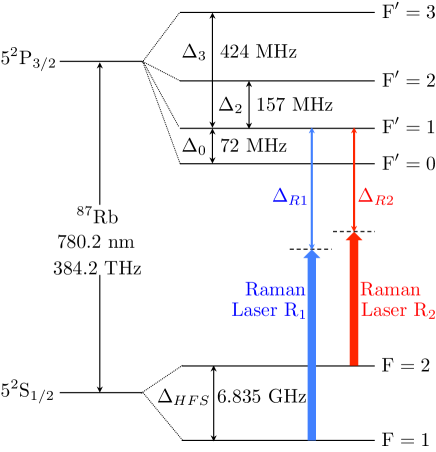
We start by recalling the general expression of the one-photon light shift onto the two hyperfine state and of an alkali atom in the presence of two Raman laser beams and detuned from the D2 line, respectively by and (not necessarily equal)
| (1) | |||||
| (2) |
where is the Rabi frequency of laser Raman between the ground state and the excited state , is the angular frequency of the ground state hyperfine transition and is the angular frequency of the hyperfine splittings in the excited state .
In the case of 87Rb atoms in the presence of two such Raman lasers, with the same circular polarization, these Rabi frequencies are given by
| (3) |
| (4) |
where are the simplified Rabi frequency , is the magnitude of the dipole moment of the D2 transition (C.m), and the amplitude of the electric field of the laser . Here and are defined taking the level as a reference (Figure 1). Note that for the present paper, the detunings are to be considered in the frame of the atoms. For an atom at a velocity , this detuning is thus Doppler shifted by with respect to its corresponding atomic transition (the transition), i.e., , where is the detuning of the Raman laser in the laboratory frame (or equivalently for an atom at rest).
II.1 Condition for driving Raman transitions
The two lasers and are used to induce stimulated Raman transitions between the two hyperfine states. The resonance condition in the laboratory frame for this process is given by: , where and are the laser frequencies in the laboratory frame, and and are the Doppler and recoil terms respectively Moler1992 . This is equivalent to
| (5) |
As for the coupling, it is characterized by the two-photon Rabi frequency, given by
| (6) |
where is the almost common Raman detuning , as kHz (typically on the order of 1 GHz).
II.2 Effect on the gravity induced chirp on the Differential Light Shift
For atoms in free fall in the vacuum chamber, the Doppler shift increases linearly with time. In our experiment, we typically let the frequency of the laser fixed, so that the detuning varies as . To fulfill the resonance condition (eq. 5), we deliberately apply a frequency ramp onto the second Raman laser (that would otherwise be Doppler shifted in the opposite direction, as being counterpropagating). This way, the frequency of both lasers in the atomic frame change by the same amount .
We calculate the effect of this frequency change on the Differential Light Shift (DLS) for the following typical parameters: = -0.923 GHz, and the Raman laser intensities of = 11 mW/cm2, = 1.74 . We take into account that in our configuration where the Raman lasers are retro-reflected on a common reference mirror, the light shift is doubled. The corresponding Rabi frequency is 22.7 kHz.
Using equations 3 and 4, we calculate a change in the light shift of Hz between the first and the last pulse of the interferometer, separated by a total interferometer time of 2 = 160 ms. This induces a phase shift onto the interferometer of = = -0.42 mrad, and a corresponding gravity shift of -0.41 Gal.
II.3 Discussion on the influence of the experimental parameters
Remarkably, in the configuration described above where the frequency chirp is applied to only one of the Raman lasers, this phase shift cannot be separated from the gravity induced phase shift using the usual technique of reversing the direction of the Raman wavevector. Indeed, this reversal requires to change the sign of the frequency chirp. The chirp induced light shift thus changes sign, as well as the gravity phase shift, so that these two contributions cannot be separated by averaging over these two measurements. Also, with contrast to the TPLS, the phase shift does not depend on the Rabi frequency: choosing a different Raman power changes in the same proportion the light shift and the Rabi frequency.
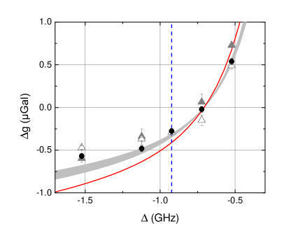
Yet, this shift depends on other parameters, such as and . The induced phase shift scales linearly with , whereas the gravity phase shift scales quadratically. The influence of this effect on the gravity measurement thus reduces when increasing . We plot as a solid red line the calculated bias on the gravity measurement as a function of the Raman detuning in figure 2. The effect is found to be monotonic with respect to the Raman detuning . Interestingly, operating at a detuning of MHz nullifies the effect.
III Measurements
III.1 Description in the experimental set-up
In our Cold Atom Gravimeter (CAG) experiment, about 87Rb atoms are loaded within 80 ms in a three-dimensional magneto-optical trap (3D-MOT) from a 2D-MOT. After a far-detuned optical molasses phase, the lasers are adiabatically switched off within 200 s and the atoms fall at a temperature of K Louchet-Chauvet2011 . During their free fall, an interrogation sequence takes place. In this study, this interrogation will be either a micro-wave spectroscopy (see section III.2) or a Raman interferometer (see section III.3). Finally, after their interrogation, the atoms are detected at the bottom of the vacuum chamber thanks to a state selective detection method which allows to measure the populations of the atoms in each hyperfine state LeGouet2008 . The total cycling time is 360 ms.
III.2 Measurement of the DLS using microwave spectroscopy
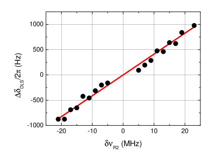
In a first series of measurements, we interrogate the atoms using microwave spectroscopy. At the end of the molasses, atoms are in the state, populating all five sub-levels. 1 ms after releasing the atoms, we apply a vertical static magnetic field of 10 mG which lifts the degeneracy between the different magnetic sub-levels. 10 ms later, we switch on a 0.4 ms microwave pulse tuned close to the hyperfine transition in order to selectively address the transition. By scanning the frequency of this microwave pulse across the hyperfine transition resonance, in the presence of the two Raman lasers set far detuned from the two photon transition, we measure the effect of the DLS as a shift of the resonance. We use this method to set the DLS to zero adjusting the ratio between the two Raman lasers. Once this power ratio adjusted, we measure, using the same method, the change of the light shift as a function of the frequency of (), keeping the frequency of fixed. Here, we deliberately change the frequency of only one laser (and not the frequencies of the two lasers by the same amount) in order to emphasize the effect. Indeed, under this condition, we calculate using equations 3 and 4 a change of of 41.3 Hz/MHz, about one order of magnitude larger than that while changing both laser frequencies (5 Hz/MHz) and thus easier to resolve. The results of the measurements are displayed on figure 3. We find a linear trend, of 41(1) Hz/MHz, in perfect agreement with the calculation, which validates our evaluation of the light shift for these lasers parameters.
III.3 Measurement of the effect of the DLS on the interferometer
In a second series of measurements, we measure the effect on the DLS onto the phase of an atom interferometer. We now turn back the Raman lasers on resonance onto the two photon transition in order to drive the atom interferometer. After their release, atoms are selected in velocity and prepared in the state using a sequence of microwave, pusher and Raman pulses. The Mach-Zehnder type interferometer realized with three Raman pulses () is performed in ms. To keep the Raman lasers (of frequency and , and wavevector and ) resonant with the atoms during their fall, the frequency of one of the two Raman lasers is chirped in order to compensate for the linearly increasing Doppler effect.
The total phase shift at the output of the interferometer is then given by , where is the phase difference between the two arms of the interferometer, the wavevector driving the atomic transitions () and the rate of the frequency chirp (Fig. 4 )).
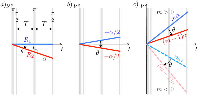
Figure 4 represents the frequencies of the two Raman lasers during the interferometer, in the case where the wavevector is pointing downward (). We now call the frequency chirp of Raman laser . In Case , the frequency of the first Raman laser is kept fixed while the frequency of Raman laser is chirped (). This setting corresponds to the measurement procedure we have used so far. In Case , both Raman lasers are chirped in opposite directions, with , so that their frequencies are fixed in the atomic frame. In that case, there is no change of the light shift, and thus no bias in the measurement. As the difference in the measurements between Cases and is expected to be small, and potentially difficult to resolve, we magnify the effect in Case , by increasing the frequency chirps applied to the lasers, while keeping their difference equal to . In practice, we apply chirp rate of to , and to , with an integer ranging in between and . Then we performed differential gravity measurements between Cases and as a function of . To remove most of the systematics effects, a measurement is obtained from the average of interleaved measurements performed with oriented upward and downward Louchet-Chauvet2011 . Such a measurement is in principle still biased by the Coriolis force, wavefront aberrations and the TPLS, but these biases are expected to be independent from the way the chirp rates are applied to the lasers. They are thus common to all cases and have no impact on the gravity differences between these cases.
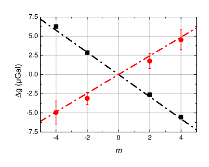
Figure 5 displays the results of the differential measurements between Cases and , for different Raman detunings of GHz and GHz at the full intensity of the Raman lasers. We find linear trends for each detuning with slopes of -1.45(3) Gal/ at GHz and 1.22(19) Gal/ at GHz. Multiplying these slopes by -0.5 gives the difference between Cases and , and thus the expected bias on the gravity measurement when operating the gravimeter with the settings of Case . We repeat the above measurement to determine the bias at other Raman detunings keeping the Raman intensity () at maximum and display the results on figure 2 as full triangles. As the Rabi frequency scales as , measurements at different detunings correspond to different Rabi frequencies and thus different Raman pulse durations. Using the same procedure, we also performed measurements at half Raman laser intensity, displayed as opened triangles, and finally at a fixed Rabi frequency of 11.4 kHz, displayed as dots in figure 2. In the latter configuration, we vary the intensity of the Raman lasers with the detuning in order to keep the Rabi frequency and thus the pulse durations constant. These three series give similar results, which confirm that the effect is independent of the Rabi frequency. When compared with the result of the calculation of section II, we obtain the correct trend, though the measured effect is weaker. For a better comparison we performed a Monte Carlo simulation of the interferometer Gillot2015 , taking into account our experimental parameters. The atoms are drawn randomly in a Gaussian position distribution of mm and in a Lorentzian velocity distribution Farah2014 ; Sortais2000 (), with parameters mm and 2.4. The Raman beam is modeled with a Gaussian beam of 12 mm waist ( radius). The simulation includes the effect of the Raman velocity selection and the response of the detection Louchet-Chauvet2011 ; Gillot2015 . It calculates the evolution of the atomic state in the interferometer, taking into account the trajectory of the atoms in the laser beams (and thus the coupling inhomogeneities), the Raman light shifts, as well as other effects which are not relevant here (such as the Coriolis acceleration and the TPLS). The result of the simulation is displayed as a gray filled area as it takes into account the uncertainty in the experimental parameters. In particular, we estimate that the adjustment of the Raman pulse parameters can deviate from optimal settings () by 5 at most from measurement to measurement. The agreement with the measurements is better, though we find resolved differences between measurements and calculations of up to 0.2 Gal for larger values of the detuning.
IV Finite speed of light
The propagation delay due to the finite speed of light introduces a bias on the measurement in classical free-fall-corner-cube gravimeters Kuroda1991 . Similar effects have been put in evidence in atom gravimeters: a significant bias of up to 10.4Gal was found in Peters2001 when dropping atoms and performing the measurement for a single orientation of the Raman wavevector.
To calculate this effect, we express the total interferometer phase shift following Borde2001 :
with the Raman laser phase difference imprinted on the atomic phase at the three pulses , considering that the pulse occurs at .
Taking into account the delay due to the propagation of the light from the very position where the phase difference between the lasers is measured (and phase locked) to the position of the atoms, we find, after some algebra,
| (7) |
with , and the Raman laser frequencies and the atom velocity at ; and are unit vectors along the direction of propagation of the lasers. By determining the position of the dark fringe, for which , we extract from equation 7 the value of ,
| (8) |
with the effective wave vector at the pulse.
Introducing , equation 8 gives:
| (9) |
which is identical to the equation 48 of Peters2001 . This equation shows that if the Raman lasers are not chirped symmetrically, the value of deviates from . In our case, where we usually operate according to case of figure 4, we find a correction that amounts to Gal for a single measurement, as the velocity at the pulse is m/s.
Magnifying the chirp rate of the and frequency by , we expect a linear scaling of this correction as a function of according to
| (10) |
This gives a correction of Gal.
In fact, the sign of this correction depends on the orientation of . When alternating the and configurations, this effect is removed when calculating the averaged value , and thus does not contribute to the results of the previous section. Alternatively, this correction can be obtained by calculating half the difference (). To separate this contribution from other systematic effects that affect this difference, we perform differential measurement taking the case as a reference according to
| (11) |
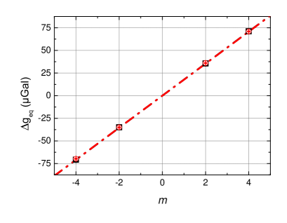
Results are displayed on figure 6 for two different Raman detunings =-0.523 GHz and =-1.523 GHz. The figure shows, as expected, no dependence in the detuning , and linear behaviors of 17.73(4) Gal for =-0.523 GHz and 17.68(6) Gal for =-1.523 GHz respectively.
These slopes differ from the result of equation 10. This arises from the fact that, in the experiment, the effective wavevector at the pulse varies with , contrary to the calculation leading to equation 10. This leads to an additional contribution given by
| (12) |
where is the duration between the start of the chirp and the moment of the pulse. It amounts to Gal. Adding equations 10 and 12, we find Gal in very good agreement with the measured slopes. This confirms our expectation that alternating between two opposite directions of the Raman wavevector allows to separate the effect of finite speed of light from that related to the change of the light shift induced by the chirp of the Raman lasers. Thus, the measurements of section III is not affected by the finite speed of light. Moreover, it strengthens our claim that our -reversal protocol for measuring rejects the effect of the finite speed of light, as stated in the accuracy budgets of the CAG when participating to metrological international comparisons Merlet2010 ; Louchet-Chauvet2011b ; Jiang2012 ; Francis2013 ; Gillot2014 ; Francis2015 .
V Conclusion
We have shown that chirping only one of the two Raman lasers to compensate for the change in the Doppler shift in a Raman interferometer based gravimeter induces a time dependent light shift, that leads to a phase shift. As this phase shift depends on the direction of the Raman wavevector, it leads to a bias in the gravity measurement that is not suppressed by the -reversal technique. We have measured the amplitude of this bias for our typical parameters, that amounts to Gal. This bias, which is smaller than our current claimed accuracy of Gal, was not accounted for in our previous measurements, and in particular, during the international comparison campaigns in which we participated.
We have performed measurements of this effect as a function of the Raman detuning, and show that this shift is independent of the Rabi frequency and varies from Gal to Gal when the detuning varies from GHz to GHz.
This effect decreases for increasing interferometer durations and thus is lower for the atomic fountain geometries such as in Peters2001 ; Zhou2011 ; Hu2013 ; Hauth2013 than when the atoms are simply dropped Bodart2010 ; Bidel2013 ; Wu2014 . In any case, it can be suppressed by chirping both Raman lasers in opposite directions. In this case, the frequencies of the lasers are constant in the frame of the atoms during their fall, so that the light shift, if any, is fixed, and rejected by the symmetry of the interferometer.
We have also performed a study of the influence of the finite speed of light which is the subject of recent controversy in the context of free falling corner cube gravimeters Nagornyi2011 ; Rothleitner2011 ; Nagornyi2011b ; Rothleitner2011b ; Rothleitner2014 ; Baumann2015 . Our measurements confirm the validity of the analysis of Peters2001 for the case of an atom gravimeter.
Acknowledgements.
B.C. thanks the Labex FIRST-TF for financial support. Authors thanks A. Landragin for useful discussions and B. Fang for carefully reading and correcting the manuscript. This research is carried on within the kNOW project, which acknowledges the financial support of the EMRP. The EMRP was jointly funded by the European Metrology Research Programme (EMRP) participating countries within the European Association of National Metrology Institutes (EURAMET) and the European Union.References
- (1) Ch. J. Bordé, Phys. Lett. A 140, number1,3, 10-12 (1989)
- (2) M. Kasevich and S. Chu, Phys. Rev. Lett. 67, 181-184 (1991)
- (3) F. Riehle, Th. Kisters, A. Witte, J. Helmcke, Ch. J. Bordé, Phys. Rev. Lett. 67, 177-180 (1991)
- (4) B. Canuel, F. Leduc, D. Holleville, A. Gauguet, J. Fils, A. Virdis, A. Clairon, N. Dimarcq, Ch. J. Bordé, A. Landragin, Ph. Bouyer, Phys. Rev. Lett. 97, 010402 (2006)
- (5) J.M. McGuirk, G. T. Foster, J. B. Fixler, M. J. Snadden and M. A. Kasevich, Phys. Rev. A 65, 033608 (2002)
- (6) F. Sorrentino, Q. Bodart, L. Cacciapuoti, Y.-H. Lien, M. Prevedelli, G. Rosi, L. Salvi and G. M. Tino, Phys. Rev. A 89, 023607 (2014)
- (7) T. L. Gustavson, A. Landragin, and M. A. Kasevich, Classical and Quantum Gravity 17, 2385 (2000)
- (8) A. Peters, K. Y. Chung, and S. Chu, Metrologia 61, 38 (2001)
- (9) A. Louchet-Chauvet, T. Farah, Q. Bodart, A. Clairon, A. Landragin, S. Merlet, F. Pereira Dos Santos, New Journal of Physics 13, 065025 (2011)
- (10) Z.-K. Hu, B.-L. Sun, X.-C. Duan, M.-K. Zhou, L.-L. Chen, S. Zhan, Q.-Z. Zhang, J. Luo, Phys. Rev. A 88, 043610 (2013)
- (11) P. Gillot, O. Francis, A. Landragin, F. Pereira Dos Santos, S. Merlet, Metrologia 51, L15-L17 (2014)
- (12) D. S. Weiss, B. C. Young, S. Chu, Appl. Phys. B 59, 217 (1994)
- (13) T.E. Mehlstäubler, J. Le Gouët, S. Merlet, D. Holleville, A. Clairon, A. Landragin, F. Pereira dos Santos, Proceedings of the XLII-th Rencontres de Moriond, La Thuile, Italy, 2007
- (14) S. Zhan, X-C. Duan, M-K. Zhou, H-B. Yao, W-J. Xu and Z-K. Hu, Optics Letters 40, No. 1, 29 (2015)
- (15) A. Gauguet, T. E. Mehlstäubler, T. Lévèque, J. Le Gouët, W. Chaibi, B. Canuel, A. Clairon, F. Pereira Dos Santos, A. Landragin, Phys. Rev. A 78, 043615 (2008)
- (16) K. Kuroda and N. Mio, Metrologia 28, 75-78 (1991)
- (17) K. Moler, D. S. Weiss, M. Kasevich, S. Chu, Phys. Rev. A, 45, 3428 (1992)
- (18) J. Le Gouët, T.E. Mehlstäubler, J. Kim, S. Merlet, A. Clairon, A. Landragin and F. Pereira dos Santos, Appl. Phys. B 92, 133-144 (2008)
- (19) P. Gillot, B. Cheng, S. Merlet and F. Pereira Dos Santos, submitted to Phys. Rev. A (2015)
- (20) T. Farah, P. Gillot, B. Cheng, A. Landragin, S. Merlet, F. Pereira Dos Santos, Phys. Rev. A 90, 023606 (2014)
- (21) Y. Sortais, S. Bize, C. Nicolas, A. Clairon, C. Salomon, C. Williams, Phys. Rev. Lett. 85, 3117 (2000)
- (22) Ch. J. Bordé, C. R. Acad. Sci. Paris, t.2, série IV, 509-530 (2001)
- (23) S. Merlet, Q. Bodart, N. Malossi, A. Landragin, F. Pereira Dos Santos, O. Gitlein, L. Timmen, Metrologia 47, L9-L11 (2010),
- (24) A. Louchet-Chauvet, S. Merlet, Q. Bodart, A. Landragin, F. Pereira Dos Santos, H. Baumann, G. D’Agostino and C. Origlia, IEEE Trans. Instr. Meas. 60, 2527-2532 (2011)
- (25) Z. Jiang et al., Metrologia 49, 666 (2012)
- (26) O. Francis, et al., Metrologia 50, 257-268 (2013)
- (27) O. Francis, et al., Metrologia 52, 07009 (2015)
- (28) L. Zhou, Z-Y. Xiong, W. Yang, B. Tang, W-C. Peng, Y-B. Wang, P. Xu, J. Wang and M-S. Zhan, Chin. Phys. Lett. Vol 28, No. 1, 013701, (2011)
- (29) M. Hauth, C. Freier, V. Schkolnik, A. Senger, M. Schmidt, A. Peters, Appl. Phys. B 113, 49 (2013)
- (30) Q. Bodart, S. Merlet, N. malossi, F. Pereira dos Santos, P. Bouyer, and A. Landragin, Applied Physics Letters 96, 134101 (2010)
- (31) Y. Bidel, O. Carraz, R. Charrière, M. Cadoret, N. Zahzam, A. Bresson, Appl. Phys. Lett. 102, 144107 (2013)
- (32) B. Wu, Z. Wang, B. Cheng, Q. Wang, A. Xu and Q. Lin, Metrologia 51, 452-458 (2014)
- (33) V. D. Nagornyi, Y. M. Zanimonskiy, Y. Y. Zanimonskiy, Metrologia 48, 101-113 (2011)
- (34) Ch. Rothleitner and O. Francis, Metrologia 48, 187-195 (2011)
- (35) V. D. Nagornyi, Y. M. Zanimonskiy, Y. Y. Zanimonskiy, Metrologia 48, 437-441 (2011)
- (36) Ch. Rothleitner and O. Francis, Metrologia 48, 442-445 (2011)
- (37) Ch. Rothleitner, T. M. Niebauer and O. Francis, Metrologia 51, L9-L13 (2014)
- (38) H. Baumann, F. Pythoud, D. Blas, S. Sibiryakov, A. Eichenberger and E. E. Klingelé, Metrologia 52, 635-645 (2015)