Enhancement of electron correlation due to the molecular dimerization in organic superconductors -(BDA-TTP) (=I3, SbF6)
Abstract
We perform a first principles band calculation for quasi-two-dimensional organic superconductors -(BDA-TTP)2I3 and -(BDA-TTP)2SbF6. The first principles band structures between the I3 and SbF6 salts are apparently different. We construct a tight-binding model for each material which accurately reproduces the first principles band structure. The obtained transfer energies give the differences such as (i) larger dimerization in the I3 salt than the SbF6 salt, and (ii) different signs and directions of the inter-stacking transfer energies. To decompose the origin of the difference into the dimerization and the inter-stacking transfer energies, we adopt a simplified model by eliminating the dimerization effect and extract the difference caused by the inter-stacking transfer energies. From the analysis using the simplified model, we find that the difference of the band structure comes mainly from the strength of dimerization. To compare the strength of the electron correlation having roots in the band structure, we calculate the physical properties originated from the effect of the electron correlation such as the spin susceptibility applying two particle self-consistent (TPSC) method. We find that the maximum value of the spin susceptibility of the I3 salt is larger than that of the SbF6 salt. Hypothetically decreasing the dimerization within the model of the I3 salt, the spin susceptibility takes almost the same value as that of the SbF6 salt for the same magnitude of the dimerization. We expect that the different ground state between the I3 and SbF6 salt mainly comes from the strength of the dimerization which is apparently masked in the band calculation along a particular -path.
pacs:
71.15.Mb, 71.10.Fd, 71.20.Rv, 74.70.KnI Introduction
There have been attempts to synthesize strongly correlated electron systems in organic conductors by applying chemical modification to stable metallic donor molecules. For example, there are (,)-DMBEDT-TTF Zambounis-Carl-am-4-33 and meso-DMBEDT-TTF Kimura-Maejima-cc–2454 , where two methyl groups are attached to BEDT-TTF, and they are pressure-induced superconductors. In the present article, we theoretically study superconductors based on BDA-TTP molecule, which is extended to six-membered-ring from five-membered-ring in the -bond framework of BDH-TTP molecule Yamada-Watanabe-JACS-104-5057 . The actual materials are -(BDA-TTP)2I3 and -(BDA-TTP)2SbF6, which will be abbreviated as I3 and SbF6 salts, respectively. In both materials, conductive layer is the BDA-TTP layer, and the anion layer separates the adjacent conductive layers as shown in Fig. 1 (a).
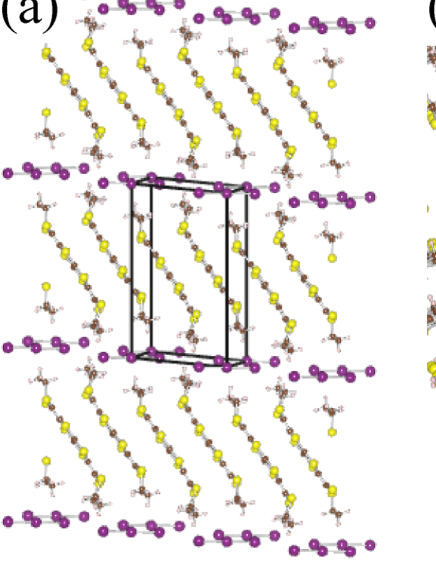
Molecular configuration in the conductive layer is the -type as shown in Fig. 1 (b). Both materials consist of the stacking structure of the BDA-TTP molecules. However, they are somewhat different in that the inter-stacking direction is slightly tilted in the I3 salt, but almost side-by-side for the SbF6 salt, which will be shown later.
The I3 salt is an insulator at ambient pressure, and the superconductivity appears around 10 K under hydrostatic pressure of above 10 kbar Yamada-Fujimoto-CC-2006-1331 . Recently, applying uniaxial strain along the -axis has given higher Kikuchi-Isono-JACS-133-19590 . Applying the uniaxial compression once increases the and takes a maximum before it decreases Ito-Ishihara-PRB-78-172506 . It is considered that applying the pressure in the I3 salt increases the overlap between the upper and lower bands, which gradually changes the character of the system from a strongly correlated half-filled system to a moderately correlated quarter filled system. The -axis strain more efficiently increases the band-width of the overlap. As the electron correlation is reduced to some extent by pressure, the insulating nature of the material is lost, and superconductivity appears Kikuchi-Isono-JACS-133-19590 . Theoretically, Nonoyama et al. have studied the nature of the charge ordering state and the pairing mechanisms in the model of the I3 salt derived from the extended Hckel band structure Nonoyama-Maekawa-JPCS-132-012013 .
The SbF6 salt exhibits superconductivity at 7.5 K at ambient pressure Yamada-Watanabe-JACS-123-4174 . As for the SbF6 salt, there have been some controversies regarding both the anisotropy of the Fermi surface Choi-Jobilong-PRB-67-174511 ; Yasuzuka-Koga-JPSJ-81-035006 and the directions of the nodes in the superconducting gap Shimojo-Ishiguro-JPSJ-71-717 ; Tanatar-Ishiguro-PRB-71-024531 ; Nomura-Muraoka-PhysicaB-404-562 ; Yasuzuka-Koga-ICSM2010-5Ax-10 . In our previous study Aizawa-Kuroki-NJP-14-113045 for the -(BDA-TTP)F6 (=P, As, Sb and Ta), we have obtained the band structure from the first principles band calculation, and suggested the origin of the differences from the extended Hckel band structurehuckel-comment . Also, there have been some studies on pairing mechanisms mediated by spin and/or charge fluctuations in the model of -(BDA-TTP). As for the F6 (= As, Sb) salts, adopting models derived from the extended Hckel calculation, Nonoyama et al. Nonoyama-Maekawa-JPSJ-77-094703 have applied random phase approximation (RPA) to the two band model, while Suzuki et al. Suzuki-Onari-JPSJ-80-094704 have applied the fluctuation exchange (FLEX) approximation to the original two-band model and the single-band dimer model. Recently, we have constructed the tight-binding model derived from the first principles band calculation, studied the pairing symmetry of the gap function within the spin fluctuation mediated pairing Aizawa-Kuroki-NJP-14-113045 .
In the present study, given the difference in the ground state between the I3 salt and the SbF6 salt, we focus on the difference in the electronic structure between the two salts. In fact, despite the similar lattice structure, the band structure of the I3 salt Yamada-Fujimoto-CC-2006-1331 and that of the SbF6 salt Yamada-Watanabe-JACS-123-4174 obtained by the extended Hckel method are known to be very different. Here, we perform the first principles band calculation for -(BDA-TTP)2I3 and construct an effective tight-binding model that reproduces the first principles band structure. We compare the band structure of the I3 salt to that of the SbF6 salt obtained in our previous studyAizawa-Kuroki-NJP-14-113045 , and pin down the origin of the apparently large differences. In particular, we study the relation between the strength of the electron correlation and the molecular dimerization. We consider the Hubbard model by introducing repulsive interaction between the electrons on the same BDA-TTP molecule. Then, we study the effect of the electron correlation by applying the two particle self-consistent (TPSC) method, and present quantities such as the spin susceptibility against the temperature and dimerization strength, which reflect physical properties originating from the electron correlation. We conclude that the ground state of the I3 salt differs from that of the SbF6 salt due to the strength of the dimerization.
II Method
II.1 first principles band calculation and model construction
We perform first principles band calculation using all-electron full potential linearized augmented plane-wave (LAPW) + local orbitals (lo) method within the framework of WIEN2k WIEN2K . This implements the density functional theory (DFT) with different possible approximation for the exchange correlation potentials. The exchange correlation potential is calculated using the generalized gradient approximation (GGA).
The single-particle wave functions in the interstitial region are expanded by plane waves with a cut-off of due to the presence of the hydrogen atom, where denotes the smallest muffin-tin radius and is the maximum value of vector in the plane wave expansion. In the I3 salt, the muffin-tin radii are assumed to be 2.50, 1.62, 1.15, and 0.62 atomic units (a.u.) for I, S, C, and H, respectively. is taken as 4.8, and the plane wave cutoff energy is 318.6 eV. In the SbF6 salt, the muffin-tin radii are assumed to be 1.74, 1.74, 1.62, 0.83, and 0.45 a.u. for Sb, F, S, C, and H, respectively. is taken as 6.7, and the plane wave cutoff energy is 604.7 eV. Calculations were performed using 639 -points for the I3 salt and 739 -points for the SbF6 salt in the irreducible Brillouin zone. We adopt the lattice structure determined experimentally for each materials Yamada-Fujimoto-CC-2006-1331 ; Yamada-Watanabe-JACS-123-4174 , and we do not relax the atomic positions in the calculation.
Having done the first principles band calculation, we then construct a tight-binding model which accurately reproduces the first principles band structure. From the lattice structure of the two materials, we regard one molecule as a site and consider a two-band (two sites per unit cell) tight-binding model to fit the first principles band structure. The tight-binding Hamiltonian, , is written in the form
| (1) |
where and are unit cell indices, and specifies the sites in a unit cell, ( ) is a creation (annihilation) operator with spin at site in the -th unit cell, is the electron transfer energy between site and site, and represents the summation over the bonds corresponding to the transfer.
By Fourier transformation, eq. (1) is rewritten as
| (2) |
where is the site-indexed kinetic energy represented in k-space. The band dispersion is given by diagonalizing the matrix ,
| (3) |
where gives the band dispersion of the -th band measured from the chemical potential, and is the unitary matrix that gives the unitary transformation.
We adopt the two-band Hubbard model obtained by adding the on-site (intra-molecule) repulsive interaction to the tight-binding model derived from the fitting of the first principles band structure. The Hubbard Hamiltonian, , is
| (4) |
where is the bare on-site interaction and is the number operator of the electron on the -site in the -th unit cell. Since both salts are configured as a form of where is the donor molecule and is the anion, the band-filling is -filled in the hole representation (-filled in the electron representation).
II.2 Two particle self consistent method
To deal with the electron correlation effect arising from the on-site repulsion, we apply TPSC to the multi-site Hubbard model given by eq. (4) as follows. The bare susceptibility in the site-representation is given by
| (5) |
where and are the temperature and the total number of unit cells, respectively, and is the bare Green’s function given as
| (6) |
Here, we introduce the abbreviations and for the fermionic and bosonic Matsubara frequencies. The indices means ( )-element of the matrix such as .
TPSC has been applied to single-site systems Vilk-Tremblay-JPIF-7-1309 ; Otuski-PRB-85-104513 , multi-site system, Arya-Sriluckshmy-arXiv-1504-06373 and multi-orbital system Miyahara-Arita-PRB-87-045113 . By applying TPSC, we can consider the local vertex correction in both spin and charge channels within a self-consistent procedure. In the TPSC, using the bare susceptibility given by eq. (5), the spin and charge susceptibilities are obtained as
| (7) | |||||
| (8) |
where () is the local spin (charge) vertex and is the unit matrix. The local vertices are determined by satisfying two sum rules for the local moment such as
| (9) | |||||
| (10) |
where is the particle number at the site . We have used the relations and from the Pauli principles.
The local spin vertex is related with the double occupancy by the following ansatz
| (11) |
where is the ( )-element of the on-site interaction matrix . Equation (11) breaks the particle-hole symmetry and should be used for . When , that can be applied through the particle-hole transformation, then the double occupancy is given by
| (12) |
where is Heaviside step function. Equations (7)-(11) give a set of the self-consistent equations for the TPSC method. Obtaining the and , the interaction for the self-energy is obtained as
| (13) |
Using the eq. (13), the self-energy is given by
| (14) |
and the dressed Green’s function is obtained as
| (15) |
Since we need two sites per unit cell, , , , , , , , , and all become 22 matrices. In the present study, the spin susceptibility is obtained as the larger eigenvalue of the 22 spin susceptibility matrix. We consider not only the spin susceptibility, but also other physical values such as the local spin vertex and the double occupancy. In the present calculation, we take the system size as -meshes and Matsubara frequencies.
III Results
III.1 first principles band calculation
Figures 2 (a) and (c) show the first principles band structures for the I3 and the SbF6 salts. For both materials, the experimental lattice structure at an ambient pressure and room temperature are used. In both of the materials, it can be seen that the highest-occupied molecular orbital (HOMO) is isolated from the lowest-unoccupied molecular orbital (LUMO). Considering this and also the number of donor molecules in a unit cell, we adopt the HOMO and HOMO1 bands as the target bands to construct an effective tight-binding model.
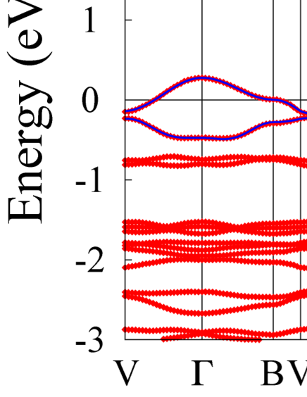
Although the difference is only the anion, the band structures of the two materials are apparently very different. In order to reveal the origin of this difference in the band structure, in the following we focus on the following two differences of the two salts. One is the magnitude of the molecular dimerization, namely the dimerization of the donor molecule in the I3 salt is larger than that in the SbF6 salt resulting in a larger gap between HOMO and HOMO1 in the former. The other is the anisotropy of the band structure, namely, there are two flat portions near the Fermi level around the Z and the X-points in the I3 salt, while there is only one flat portion around the B-point in the SbF6 salt.
Figure 2 (b) shows the Fermi surface of the first principles band calculation for the I3 salt, where the high symmetry points in the Brillouin zone are presented only on the plane. The Fermi surface of the I3 salt is disconnected, namely quasi-one-dimensional, but it is actually close to two dimensional because a slight shift of the band structure around the Z-point would give a closed (i.e. 2D) Fermi surface. Figure 2 (d) shows the Fermi surface of the SbF6 salt. The Fermi surface is cylindrical, reflecting the two-dimensionality of this salt as shown in our previous work Aizawa-Kuroki-NJP-14-113045 .
III.2 Effective tight-binding model
Figure 3 shows the effective tight-binding model adopted to fit the first principles band. The nearest-neighbor transfers are shown in the left panel of Fig. 3, and in addition we also need to introduce the next-nearest-neighbor transfers shown in the right panel of Fig. 3 to reproduce the first principles band structure more accurately. Note that the stacking direction of the BDA-TTP molecules is taken in the -directionnote_coodinates . The band dispersions of the tight-binding model are shown as blue solid curves in Fig. 2 (a) for the I3 salt and Fig. 2 (c) for the SbF6 salt.
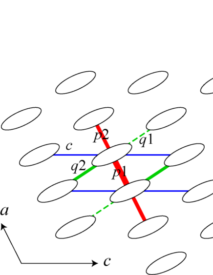
The transfer energies for the two salts are summarized in Table 1. The bottom three lines represent the magnitude of the dimerization which is measured by the ratio , and the transfer between the inter-stacking direction normalized by the average value of intra-stacking transfer energies, and . From Table 1, it can be seen that there are two major differences between the two salts. One is the strength of the molecular dimerization, namely the dimerization in the I3 salt is larger than that in the SbF6 salt. Another difference is the transfers in the inter-stacking direction namely, the magnitudes as well as the sign of the inter-stacking transfers are different between the two salts, that is in ()-direction in the I3 (SbF6) salt.
| I3 | SbF6 | |
| (eV) | -0.174 | -0.153 |
| -0.102 | -0.126 | |
| 0.018 | -0.071 | |
| 0.041 | -0.055 | |
| 0.062 | 0.007 | |
| 0.002 | 0.005 | |
| 0.006 | 0.021 | |
| -0.001 | 0.003 | |
| 0.004 | 0.005 | |
| -0.012 | 0.003 | |
| 0.013 | 0.006 | |
| 0.002 | 0.014 | |
| 0.009 | 0.008 | |
| 0.586 | 0.824 | |
| -0.214 | 0.452 | |
| -0.449 | -0.050 |
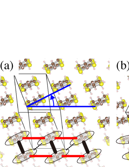
To clarify the origin of the differences between the two salts, we consider the alignments of the donor molecules in the conducting - plane for the two salts. The conducting - plane for each salt is shown in Fig. 4. We find that the tilting angle of the donor molecules from the -axis is different between the two salts. In the I3 salts shown in Fig. 4 (a), the tilting angle is larger than that in the SbF6 salts shown in Fig. 4 (b). The difference in the tilting angle gives rise to differences in both the magnitude and the sign of the main inter-stacking transfers, which is in the I3 salt shown in the lower panel of Fig. 4 (a), while they are and in the SbF6 salt shown in the lower panel of Fig. 4 (b).
Now, let us try to decompose these differences. We consider a case where we hypothetically eliminate the dimerization effect. Namely, we simplify the model by considering only the nearest neighbor transfer energies, and replace the hopping in the - and -directions by taking their averages. The band structure of the simplified model is given by
| (16) |
where the transfer energies are eV, eV, eV for the I3 salt, and eV, eV, eV for the SbF6 salt. Eliminating the dimerization effect enables us to take the unit cell reduced along the -direction. By comparing the band structure of the simplified model, we can extract the difference caused by the inter-stacking transfer.
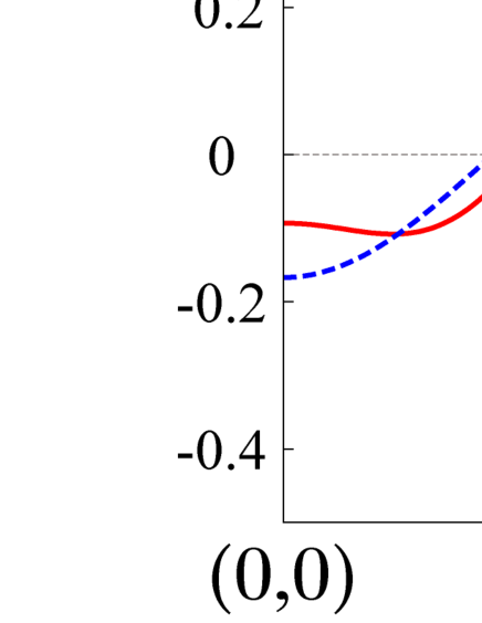
We compare the band structure of the two salts in the plane, where is taken in the molecular stacking direction and is taken in the direction of the main inter-stacking transfer, namely, -direction in the I3 salt (Fig. 5 (a)) and -direction in the SbF6 salt as seen in Fig. 5 (b). Also, we shift the wave-number by for the SbF6 salt considering the sign difference in the main transfer energies along the inter-stacking direction. By such a transformation, we find that the band structures between the I3 salt and the modified SbF6 salt become very similar as shown in Fig. 5 (c). Since the simplified model eliminates the dimerization effect, the difference in the original band structure between the two salts comes mainly from the dimerization, and the differences coming from the inter-stacking transfer are not essential.
III.3 Effect of electron correlation cooperating with dimerization
A quarter-filled system effectively becomes a half-filled system by increasing the dimerizationKino-Fukuyama-JPSJ-65-2158 , so that the electron correlation is strengthened. Since we now know that the strength of the dimerization is the essential difference between the I3 and SbF6 salts, we expect that the difference of the ground state physical properties between the two salts is caused by the strength of the electron correlation originating from the difference in the strength of the dimerization.
The strength of the electron correlation can be measured by calculating the spin susceptibility. We apply the TPSC scheme to the Hubbard model of the I3 salt. From the first principles calculation of the I3 salt, the band width is about 0.77eV, so we take the on-site interaction eV as same as the band width. The bare on-site interaction is estimated in the other strongly correlated organic conductors applying the first-principles calculation Nakamura-Yoshimoto-JPSJ-78-083710 ; Nakamura-Yoshimoto-PRB-86-205117 . Referring to them, the on-site interaction we taken is appropriate.
Figure 6 (a) shows the temperature dependence of the local vertex of the spin part and the critical on-site interaction of the magnetic order in the left scale. Above the temperature eV, is almost unchanged and gradually decreases with lowering the temperature. Below eV, takes almost the same value, but somewhat smaller value than , which can be understood that the magnetic ordering is developed with lowering the temperature.
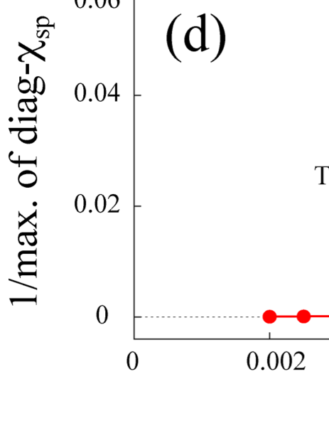
In the right scale of Fig.6(a), we present the ratio as a function of . The TPSC approach satisfies the Mermin-Wagner theorem so the true magnetic ordering does not occur in the present model, but we can regard the temperature at which the line extrapolating from high temperature reaches unity as the magnetic critical temperature in the actual three dimensional system. We estimate the magnetic critical temperature to be about 0.0038 eV. Reflecting the tendency toward the magnetic ordering, quickly increases below eV as shown in Fig. 6 (b). We show the double occupancy as a function of in Fig. 6 (c). Similarly to the local vertices, the double occupancy also changes below eV. Decreasing the temperature reduces the double occupancy, which means the tendency of the magnetic localization at each site. Figure 6 (d) shows the inverse of the maximum value of the spin susceptibility against . As expected from Fig. 6 (a), the inverse of the spin susceptibility extrapolates to zero around eV. In fact, a very recent experiment observes a magnetic transition in the Mott insulating state of the salt at low temperature Isono-private-communication . TPSC is not capable of directly describing the magnetic ordering of a Mott insulator, but the very fact that the material is a Mott insulator is consistent with our view that the electron correlation effect is strong due to the strong dimerization.
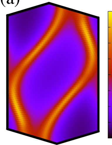
Figures 7 (a) and (b) show the absolute value of the Green’s function and the spin susceptibility of the I3 salt with eV and eV. The absolute value of the Green’s function takes large values near the Fermi surface shown in Fig. 7 (a). The wave number at which the spin susceptibility is maximized corresponds to the nesting vector of the Fermi surface as seen in Fig. 7 (b). As shown in Fig. 7 (b), the maximum value of the spin susceptibility takes a large value since its temperature is close to the critical temperature.
To clarify the relation between the electron correlation and the dimerization, we measure the strength of the dimerization by the quantity . When goes to unity, the dimerization decreases. If the decrease of the dimerization results in weakening the electron correlation, we expect (i) gradually deviates from , (ii) the double occupancy becomes large, and (iii) the maximum value of the spin susceptibility decreases within the TPSC scheme. Furthermore, if the stronger electron correlation of the I3 salt originates from the stronger molecular dimerization, all the quantities should approach the values close to those of the SbF6 salt when the dimerization is reduced hypothetically in the model of the I3 salt.
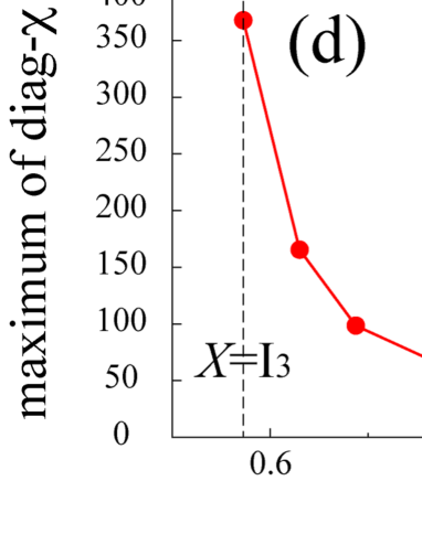
Let us now investigate the relation between the electron correlation and the dimerization. Figure 8 (a) shows the local vertex of the spin part and the critical on-site interaction for the magnetic order as a function of in the model of the I3 salt, also shows them for the SbF6 salt at the point corresponding , where we take eV. Decreasing the dimerization (increasing ), gradually differs from , which expects that increasing the suppresses the maximum value of the spin susceptibility. In contrast to the temperature dependence, decreasing the dimerization increases as seen in Fig. 8 (b), although differs from the . In Fig. 8 (c), the double occupancy monotonically increases with decreasing the dimerization, which can be understood as the suppression of the magnetic localization. This tendency is confirmed by the deviation of from . Figure 8 (d) shows the maximum value of the spin susceptibility as a function of . Decreasing the dimerization from the actual value of the I3 salt quickly suppresses the spin susceptibility, and that of the I3 salt takes almost the same value as that of the SbF6 salt around the same strength of the dimerization.
From the dependence in Fig. 8, we can say that the electron correlation in the I3 salt is stronger than in the SbF6 salt due to the strong dimerization. We therefore conclude that the difference of the ground state between the two salts, namely, insulating for the I3 salt and superconducting for the SbF6 salt, originates from the strength of the dimerization, which affects the electron correlation. Applying the pressure to the I3 salt reduces the dimerization, resulting in the metallicity, and hence the superconductivity appears.
IV Conclusion
In the present study, we have performed first principles band calculations and have derived the effective tight-binding models of -(BDA-TTP)2I3 and -(BDA-TTP)2SbF6. The band structures and the Fermi surface between the I3 and SbF6 salts are apparently different although only the anion differs. The derived tight-binding models, which accurately reproduce the first principles band structures of the two salts, show that the differences between the two salts comes mainly from the strength of the dimerization.
As for the effect of the electron correlation, we have presented the TPSC results for quantities such as the spin susceptibility in the Hubbard model for the two salts. The TPSC results show that the electron correlation becomes stronger upon lowering the temperature and/or increasing the dimerization strength. Then, we have hypothetically reduced the strength of the dimerization in the I3 salt to that of the SbF6 salt, where all the calculated quantities tend to become similar to those of the SbF6 salt. Thus, we conclude that the electron correlation in the I3 salt is stronger than the SbF6 salt due to the strong dimerization. The expected stronger correlation in the I3 salt is at least qualitatively consistent with a recent experimental observation that the material is a Mott insulator, which is a hallmark of strong correlation, and exhibits a magnetic transition at low temperature Isono-private-communication . Applying the pressure to the I3 salt reduces the dimerization, which weakens the electron correlation, and hence the superconductivity appears as in the SbF6 salt.
In the present study, we have considered only the on-site (intra-molecular) electron-electron interaction. It remains an interesting future problem to study the effect of the off-site interactions. In fact, it has been known that in organic conductors having quarter-filled bands, the Mott insulating state often competes with the charge ordering and/or charge-density-wave statesSeo-Merino-JPSJ-75-051009 . It is an interesting issue to investigate how such interactions would affect the insulating properties as well as the mechanism of the superconductivity.
Acknowledgment
We thank T. Isono for showing the latest experimental data. This work is supported by Grant-in-Aid for Scientific Research from the Ministry of Education, Culture, Sports, Science and Technology of Japan, and from the Japan Society for the Promotion of Science. Part of the calculation has been performed at the facilities of the Supercomputer Center, ISSP, University of Tokyo.
References
- (1) J. S. Zambounis, C. W. Mayer, K. Hauenstein, B. Hilti, W. Hofherr, J. Pfeiffer, M. Brkle, and G. Rihs, Adv. Matter. 4, 33 (1992).
- (2) S. Kimura, T. Maejima, H. Suzuki, R. Chiba, H. Mori, T. Kawamoto, T. Mori, H. Moriyama, Y. Nishio, and K. Kajita, Chem. Commun. , 2454 (2004).
- (3) J. Yamada, H. Akutsu, H. Nishikawa, and K. Kikuchi, Chem. Rev. 104, 5057 (2004).
- (4) J. Yamada, K. Fujimoto, H. Akutsu, S. Nakatsuji, A. Miyazaki, M. Aimatsu, S. Kudo, T. Enoki, and K. Kikuchi, Chem. Commun., 1331 (2006).
- (5) K. Kikuchi, T. Isono, M. Kojima, H. Yoshimoto, T. Kodama, W. Fujita, K. Yokogawa, H. Yoshino, K. Murata, T. Kaihatsu, H. Akutsu, and J. Yamada, J. Am. Chem. Soc. 133, 19590 (2011).
- (6) H. Ito, T. Ishihara, H. Tanaka, S. Kuroda, T. Suzuki, S. Onari, Y. Tanaka, J. Yamada, and K. Kikuchi, Phys. Rev. B 78, 172506 (2008).
- (7) Y. Nonoyama, Y. Maekawa, A. Kobayashi, Y. Suzumura, and J. Yamada, J. Phys.: Conf. Ser. 132, 012013 (2008).
- (8) J. Yamada, M. Watanabe, H. Akutsu, S. Nakatsuji, H. Nishikawa, I. Ikemoto, and K. Kikuchi, J. Am. Chem. Soc. 123, 4174 (2001).
- (9) E. S. Choi, E. Jobilong, A. Wade, E. Goetz, J. S. Brooks, J. Yamada, T. Mizutani, T. Kinoshita, and M. Tokumoto, Phys. Rev. B 67, 174511 (2003).
- (10) S. Yasuzuka, H. Koga, Y. Yamamura, K. Saito, S. Uji, T. Terashima, H. Aizawa, K. Kuroki, M. Tsuchiizu, H. Akutsu, and J. Yamada, J. Phys. Soc. Jpn. 81, 035006 (2012).
- (11) Y. Shimojo, T. Ishiguro, T. Toita, and J. Yamada, J. Phys. Soc. Jpn. 71, 717 (2002).
- (12) M. A. Tanatar, T. Ishiguro, T. Toita, and J. Yamada, Phys. Rev. B 71, 024531 (2005).
- (13) K. Nomura, R. Muraoka, N. Matsunaga, K. Ichimura, and J. Yamada, Physica B 404, 562 (2009).
- (14) S. Yasuzuka, private communications.
- (15) H. Aizawa, K. Kuroki, S. Yasuzuka, and J. Yamada, New J. Phys. 14, 113045 (2012).
- (16) Recently, several studies report that the first-principles band structure slightly differs from those obtained by the extended Hckel method Kandpal-Opahle-PRL-103-067004 ; Nagai-Nakamura-PRB-83-104523 ; Alemany-Pouget-PRB-89-155124 .
- (17) H. Kandpal, I. Opahle, Y.-Z. Zhang, H. Jeschke, and R. Valent, Phys. Rev. Lett. 103, 067004 (2009).
- (18) Y. Nagai, H. Nakamura, and M. Machida, Phys. Rev. B 83, 104523 (2011).
- (19) P. Alemany, J.-P. Pouget, and E. Canadell, Phys. Rev. B 89, 155124 (2014).
- (20) Y. Nonoyama, Y. Maekawa, A. Kobayashi, Y. Suzumura, and H. Ito, J. Phys. Soc. Jpn. 77, 094703 (2008).
- (21) T. Suzuki, S. Onari, H. Ito, and Y. Tanaka, J. Phys. Soc. Jpn. 80, 094704 (2011).
- (22) P. Blaha, K. Schwarz, G. K. H. Madsen, D. Kvasnicka, J. Luitz In WIEN2K, An Augmented Plane Wave + Local Orbitals Program for Calculating Crystal Properties, (Karlheinz Schwarz/ Techn. Universitt Wien, Wien, Austria, 2001).
- (23) Y. M. Vilk, A. -M. S. Tremblay, J. Phys. I France 7, 1309 (1997).
- (24) J. Otsuki, Phys. Rev. B 85, 104513 (2012).
- (25) S. Arya, P. V. Sriluckshmy, S. R. Hassan, and A. -M. S. Tremblay, arXiv:1504.06373.
- (26) H. Miyahara, R. Arita, and H. Ikeda, Phys. Rev. B 87, 045113 (2013).
- (27) For correspondence with our previous study Aizawa-Kuroki-NJP-14-113045 , the lattice coordinates c and a taken in the SbF6 salts correspond with and in the I3 salts according to the structure data for both materials. Yamada-Fujimoto-CC-2006-1331 ; Yamada-Watanabe-JACS-123-4174 Similarly, the notation of the transfer energies is different. We employ the lattice coordinates and notation of the I3 salts in this article.
- (28) H. Kino, and H. Fukuyama, J. Phys. Soc. Jpn. 65, 2158 (1996).
- (29) K. Nakamura, Y. Yoshimoto, T. Kosugi, R. Arita, and M. Imada, J. Phys. Soc. Jpn. 78, 083710 (2009).
- (30) K. Nakamura, Y. Yoshimoto, and M. Imada, Phys. Rev. B 86, 205117 (2012).
- (31) T. Isono, private communication.
- (32) For a review, H. Seo, J. Merino, H. Yoshioka, and M. Ogata, J. Phys. Soc. Jpn. 75, 051009 (2006).