suppSupp References
Bio-Inspired Aggregation Control of Carbon Nanotubes for Ultra-Strong Composites
Abstract
High performance nanocomposites require well dispersion and high alignment of the nanometer-sized components, at a high mass or volume fraction as well. However, the road towards such composite structure is severely hindered due to the easy aggregation of these nanometer-sized components. Here we demonstrate a big step to approach the ideal composite structure for carbon nanotube (CNT) where all the CNTs were highly packed, aligned, and unaggregated, with the impregnated polymers acting as interfacial adhesions and mortars to build up the composite structure. The strategy was based on a bio-inspired aggregation control to limit the CNT aggregation to be sub 20–50 nm, a dimension determined by the CNT growth. After being stretched with full structural relaxation in a multi-step way, the CNT/polymer (bismaleimide) composite yielded super-high tensile strengths up to 6.27–6.94 GPa, more than 100% higher than those of carbon fiber/epoxy composites, and toughnesses up to 117–192 MPa. We anticipate that the present study can be generalized for developing multifunctional and smart nanocomposites where all the surfaces of nanometer-sized components can take part in shear transfer of mechanical, thermal, and electrical signals.
A composite material is typically made up of two or more constituent materials with significantly different physical or chemical properties, and is also named a nanocomposite when one of the constituents has one, two, or three dimensions of less than 100 nm. To design the structure for high performance and multifunctional composites, nature has offered us with scientific and technological clues from the formation of biological composites using common organic components via the naturally mild approaches ha.tlb:2013 . For example, super-tough spider fibers are derived from desirable organization of linear protein molecules giesa.t:2011 , strong hard nut skins are assembled from the mixture of cellulose and lignin molecules preston.cm:1992 , and wear-resistant molluscan shells are a result of biomineralization of calcium carbonates in a brick-and-mortar manner porter.sm:2007 . To make these natural composites mechanically strong, a homogeneous distribution of the major components such as proteins, cellulose molecules, and nanometer-sized crystals of carbonated calcium phosphates or calcium carbonates is a key structural feature giesa.t:2011 ; cheng.qf:2014 . Their desired orientation along with other co-existing components also sheds lights on the way to stronger man-made nanocomposites. This means, in order to fabricate high performance nanocomposites, the fraction of nanometer-sized components should be as high as possible, while the other components should act as interfacial adhesions and mortars to combine the major parts together. As a result, the interfacial contacts or bondings can be maximized to allow full utilization of the unique properties of the nanometer-sized components.
Owing to the superior mechanical properties of carbon nanotubes (CNTs), many composite structures have been proposed for pursuing a wide range of industrial applications of CNT over the past two decades baughman.rh:2002 ; coleman.jn:2006 ; moniruzzaman.m:2006 ; liu.lq:2011 ; kong.lr:2014 . As CNTs are difficult to be uniformly dispersed within polymer matrix at a high mass fraction due to their strong tendency to agglomerate coleman.jn:20062 ; fiedler.b:2006 ; xie.xl:2005 ; spitalsky.z:2010 ; rahmat.m:2011 , it is still a challenge to fabricate CNT composites that mimic the natural ones. Fortunately, CNTs can be treated as linear macromolecules, and thus the processing on them can be dealt with in a biomimic way. To mimic the formation process of biological composites, the preformed two-dimensional (2D) CNT assemblies like sheets and films, whose thickness is within tens to hundreds of nanometer or over 1 , are interesting candidates liu.lq:2011 ; zhang.m:2005 . By introducing thermosetting polymers like bismaleimide (BMI) into these 2D assemblies, it has been possible to synthesize CNT composites at a high CNT mass fraction cheng.qf:2009 ; cheng.qf:2010 ; liu.w:2011 ; di.jt:2012 ; wang.x:20131 , whose tensile strength was even higher than that of T300 carbon fiber/epoxy composites (1.86 GPa) t300 . However, besides the high length-to-width aspect ratio and high mass fraction, a set of structural parameters are still severely required, such as a high CNT packing density and alignment, efficient matrix-to-CNT interfacial stress transfer, and, most importantly, the avoid of CNT aggregation wagner.hd:2007 .
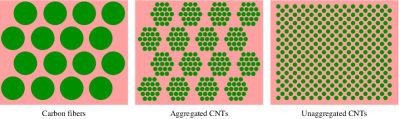
The necessity of aggregation control can be demonstrated by a comparison between the structures of carbon fiber reinforced polymer and CNT composites containing aggregated and unaggregated CNTs, as schematically shown in Figure 1. The most important advantage of CNTs is the large contact area between CNTs and matrix, similar to the natural composite structures. When solid carbon fibers are replaced by the aggregated CNTs, as commonly observed in today’s CNT composites cheng.qf:2009 ; cheng.qf:2010 ; liu.w:2011 ; di.jt:2012 ; wang.x:20131 , the interfacial contact area becomes much larger. The composites based on aggregated CNTs have exhibited tensile strengths ranging from 2.08 to 3.8 GPa cheng.qf:2009 ; cheng.qf:2010 ; wang.x:20131 . However, the aggregation phase might act as weak parts in transferring external loads and thus hinders the further reinforcement. In an ideal structure where all the interfaces can play roles in shear load transfer, the nanometer-sized components should be uniformly distributed within the matrix and there should be no aggregation for either the matrix or the nanometer-sized structures.
Here we report a big step to approach such ideal structure where the composite structure contained highly aligned and unaggregated CNT bundles. By learning the formation process of biological composites, polymers were impregnated into CNT networks to obtain the uniform dispersion of the CNTs among the polymer matrix. As the CNTs were well covered by the polymers, sufficient stretching exercises were performed to improve the CNT alignment with maintaining the CNT aggregation level below 20–50 nm, and to increase the mass density as well. The new CNT composites exhibited ultra-high and stable tensile strengths up to 6.27–6.94 GPa and toughnesses up to 117–192 MPa, corresponding to the energies absorbed before rupturing of 75–124 by considering the mass density of 1.55 . Such tensile strengths have been more than 100% higher than those of carbon fiber/epoxy composites. The processing method is supposed to be generalized for developing multifunctional and smart nanocomposites where all the surfaces of nanometer-sized components can take part in shear transfer of mechanical, thermal, and electrical signals.
Entangled CNT network. The CNT aggregation arises from van der Waals (vdW) attraction and can be enhanced in wet environment. The situation becomes very severe in the layer-by-layer stacking of aligned CNT sheets with the aid of solution spray to obtain high performance CNT films liu.w:2011 ; di.jt:2012 ; wang.x:20131 , where the CNTs (or more commonly, small-sized CNT bundles) usually aggregate first into large-sized bundles and then are surrounded by polymer matrix, as discussed below. Instead, preformed CNT networks can be the optimal raw materials cheng.qf:2009 ; cheng.qf:2010 .
The networked CNTs were synthesized by using an injection chemical vapor deposition (CVD) method li.yl:2004 , where a mist of ethanol, ferrocene, and thiophene was injected into a heated gas flow reactor (see Supplementary Information). The grown CNTs cross-linked with each other, formed a sock-like aerogel in the gas flow, and were blown out with the carrier gas, a mixture of Ar and \ceH2. By continuously winding the CNT aerogel on a roller with the aid of ethanol densification, CNT films with a thickness of 10–30 were obtained.
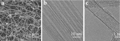
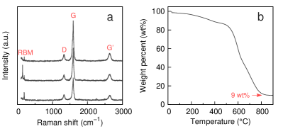
Scanning electron microscopy (SEM) and transmission electron microscopy (TEM) have shown that the basic structural units of the as-produced CNT films were small-sized bundles (Figure 2a), with a diameter of 40–50 nm and containing about 50 CNTs (Figure 2b). The CNTs in a bundle usually grew out of the same iron catalyst nanoparticle and thus became always bundled during the growth. Under the gas flow, the bundles contacted with each other and finally formed an entangled assembly structure. The CNTs were mainly double-walled and had a diameter of 1–2 nm (Figure 2c), and were confirmed with Raman spectroscopy (see Supplementary Information, Figure S1). The as-produced CNT films had a high level of crystallinity as reflected by the high G to D-band Raman intensity ratio, and the CNT mass fraction was over more than 90% (see Supplementary Information, Figure S1). Furthermore, nitrogen adsorption/desorption measurement revealed a specific surface area of 119 .
Impregnation without introducing aggregation. It is very important to find that the CNT entanglement was not altered after liquid densification. After further being densified with acetone, the pore sizes of CNT films decreased from 500 nm (Figure 2a) to 100–200 nm (see Supplementary Information, Figure S2), while the feature of random distribution and unaggregation did not change. Such process is reminiscent of the formation process of biological composites, where the matrix co-exists with and disperses the major components as they are simultaneously grown from stem cells. Their fractions are always optimized during the growth to allow the maximized interfacial stress transfer wagner.hd:2007 . Thus the processing sequence was modified to introduce impregnation of polymer solution prior to any other processing that might damage the network, to avoid CNT aggregation. (Notice that, besides the severe CNT aggregation liu.w:2011 ; di.jt:2012 ; wang.x:20131 , the pre-aligned CNT sheets drawn out of CNT arrays zhang.m:2004 are not favorite also because that it is difficult to wet them as they are mechanically very weak.)
By appropriately using acetone as solvent to dissolve thermosetting polymers or their resins, like BMI resins, the polymers can efficiently cover all the CNT surfaces. Excitingly, neither the CNTs nor the resins formed aggregated phases; there did not exist a region filled with only CNTs or BMI resins above a size scale of 50–100 nm (see below the detailed characterization). The entanglement played the key role, because the capillary force due to solvent evaporation and the vdW interaction between CNT and resin could densify the assembly by drawing the CNTs closer, but these interactions were not strong enough to break the network cross-links and thus to aggregate the CNTs.
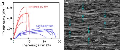
High alignment and ultra-high strengths. Stretching should be provided to re-assemble the network and align CNTs. This requires the samples to possess high plasticity. The raw films could be stretched by 10–15% in length and owing to the improved alignment their tensile strength increased from 180–198 to 500–600 MPa (see Supplementary Information, Figure S3). For the “wet” films where 1 wt% BMI resin/acetone solutions were impregnated to reach a CNT-to-resin mass ratio of 7:3 or 8:2, the unstretched films became more plastic and fractured above a strain of 20–25%, corresponding to higher processability (see Supplementary Information, Figure S4). This means that the impregnation prior to stretching also resulted in improved processability.
If hot-pressing was applied on the unstretched films to cure resins, the CNT/BMI films finally exhibited a tensile strength just of 478–501 MPa and strain at break of 10–12.2%. On the contrast, by first stretching the “wet” film by 20% and then curing the film, the tensile strength and strain at break became 1.74–1.92 GPa and 3.4–5.2%, respectively (see Supplementary Information, Figure S6).
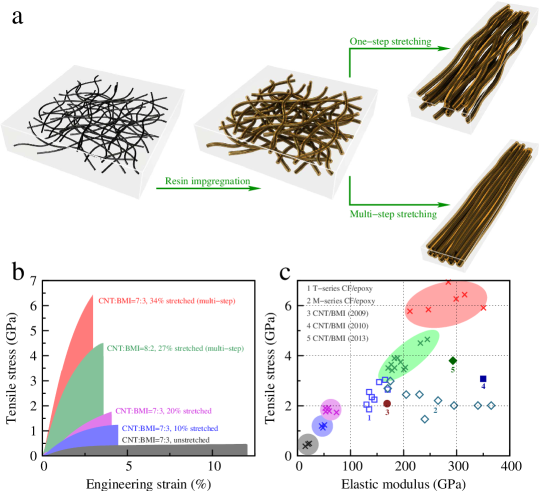
Nevertheless, 2 GPa was not the up limit. By further modifying the stretching method to a multi-step way (Figure 3a), the “wet” films could be stretched by 27–34%. The total stretching process was carried out in multiple steps. In each step 3% additional stretching according to the immediate film length was applied and then 5–10 minutes were used to relax the films. The total stretching magnitude, for example, was or for 8 or 10 steps, respectively. The multi-step method fully aligned the CNTs and improved packing density during the hot-pressing (owing to the decreased level of CNT waviness and less unstretched network connections). At this stage, the basic structural units (the small-sized CNT bundles) were well surrounded by the BMI resin molecules and maintained unaggregated phases. After being cured, the CNT/BMI composite films stably exhibited an extremely high tensile strength up to 4.5–6.94 GPa (Table 1, and also see Supplementary Information, Figure S7), depending on the CNT-to-resin mass ratio and the total stretching magnitude. At the same time, the elastic modulus was up to 232–315 GPa and the strain at break became 2.7–4.5%. Figure 3b shows the typical stress-strain curves for various CNT/BMI composite films and Figure 3c provides the comparison with carbon fiber/epoxy composites.
| Toughness | Strain at break | |||
| No. | Strength (GPa) | Modulus (GPa) | (MPa) | (%) |
| CNT-to-resin ratio 7:3, multi-step stretched by 34% | ||||
| 1 | 6.940 | 284.2 | 191.7 | 4.33 |
| 2 | 6.438 | 314.9 | 114.6 | 2.97 |
| 3 | 6.265 | 299.0 | 117.1 | 3.10 |
| 4 | 5.907 | 350.6 | 82.1 | 2.34 |
| 5 | 5.842 | 246.8 | 104.3 | 3.17 |
| 6 | 5.773 | 211.9 | 163.2 | 4.49 |
| CNT-to-resin ratio 7:3, multi-step stretched by 25% | ||||
| 1 | 6.309 | 148.7 | 197.9 | 5.41 |
| 2 | 5.781 | 127.9 | 173.3 | 5.41 |
| 3 | 5.130 | 168.0 | 187.4 | 5.47 |
| 4 | 4.467 | 111.3 | 127.1 | 5.02 |
| 5 | 4.266 | 146.5 | 123.8 | 4.51 |
| 6 | 3.826 | 153.6 | 100.4 | 3.95 |
| CNT-to-resin ratio 8:2, multi-step stretched by 27% | ||||
| 1 | 4.651 | 244.7 | 83.0 | 2.87 |
| 2 | 4.505 | 231.5 | 105.9 | 3.58 |
| 3 | 3.748 | 194.3 | 89.8 | 3.58 |
| 4 | 3.646 | 176.6 | 92.9 | 3.84 |
| 5 | 3.515 | 183.0 | 83.3 | 3.60 |
| 6 | 3.506 | 170.9 | 78.3 | 3.38 |
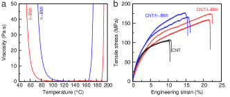
Effect of low-softening-point resins. The high mechanical performance also came from the low-softening-point (60 ) BMI resins (l-BMI) which were traditional BMI monomers modified with diallyl bisphenol A (DBA) li.zm:2001 . As a comparison, the same DBA modification was applied on BMI monomers with larger molecular weights and higher molecular rigidity, to synthesize BMI resins with higher softening point of 80 (h-BMI). The low softening point resulted in a soft and viscous state even at room temperature, like soft wax, and thus the CNT film impregnated with BMI resins was called as a “wet” film. The less-“wet” CNT/h-BMI films (CNT-to-resin mass ratio 7:3) could be only stretched directly by 16% while the “wet” CNT/l-BMI films (7:3) were by 20% (see Supplementary Information, Figure S5). Of great importance, the “wet” feature also allowed structural relaxation as sufficient as possible during the multi-step stretching process. Notice that, the 16%-stretched CNT/h-BMI composite films exhibited a tensile strength of 1.5 GPa, as comparable to the CNT/l-BMI composites (see Supplementary Information, Figure S6), indicating that the major difference of the resins was the plasticizing ability rather than the strengthening ability.
Structural characterization. Based on these advantages, including the unaggregation and high alignment, we have made a big step to realize the ideal composite structure. The tensile strength of 6 GPa is obviously much larger than those of carbon fiber/epoxy composites (Figure 3), in good agreement with their different composite structures (Figure 1). To show how much the present structure had approached the ideal one, comparison was performed between the layer-by-layer stacked array-drawn CNT sheets, highly stretched film with entangled CNTs, and the optimal and ultra-strong CNT/BMI composite films (Figure 4a-c). In the first two cases, CNT aggregation was widely observed in a scale of hundreds of nanometer (Figure 4a,b), while the small-sized CNT bundles did not aggregate but were surrounded and adhered with each other by BMI polymers in the optimal composite structure (Figure 4c).
Thermal treatment at 750 in Ar for 1.5 h was performed on the CNT/BMI composite films to decompose BMI polymers. After the decomposition, the remaining BMI polymers formed flake-like particles, and thus exposed the CNTs which might maintain their aggregation level. Therefore this method can serve as evidences for CNT aggregation and unaggregation. Two CNT/BMI composite films were tested, where the stretching process was performed before and after the impregnation of BMI resins, respectively. As shown in Figure 4d and e, there was clearly no aggregation of CNT bundles by using our new processing method.
It was possible to observe directly the cross section of the optimal structure by using focused ion beam treatment (Figure 4f). Although it was difficult to distinguish individual CNTs, the small-sized CNT bundles were pictured perpendicular to the cross section and polymer matrix surrounded all their surfaces. Such homogeneity maximized interface contacts and thus provided the most efficient CNT-to-polymer stress transfer. By considering the fact that the bundling within a dimension of 20–50 nm was only determined during the growth, there is still a last step to obtain the ideal structure where individual CNTs are aligned, highly packed, and unaggregated.
Furthermore, it is no doubt that the stretching treatment improved the CNT alignment, nevertheless, quantitative characterization of alignment is still of great interest. In the present study, the characterization was represented by the Herman’s orientation factor (HOF) which has been used to study the alignment level for CNT arrays xu.m:2012 . HOF takes the value 1 for a system with full alignment and zero for completely nonoriented structures. The HOF of the original film was only 0.209, well reflecting the random CNT distribution. After being stretched by about 20% and 34%, the HOF increased remarkably up to 0.632 and 0.816, respectively. (The calculation method and the detailed results are provided in Supplementary Information.)
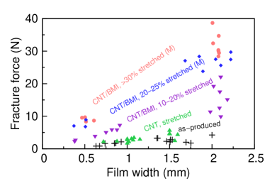
Specific strengths. Another way to describe the tensile property is specific strength, also known as the strength-to-weight ratio. In this way it not necessary to know the film thickness. For the films multi-step stretched by 25% in length, the total mass for a 2 cm1 cm sample was 1.15 mg, corresponding to an area density of 0.58 . The fracture force per sample width was about 16.5 in average (see Supplementary Information, Figure S12), and thus the specific strength (by dividing the force per width by the area density) was 2.87 . When the stretching magnitude was improved to 34%, the fracture force per width was 19.5 (see Supplementary Information, Figure S12), the area density decreased slightly to 0.46 , and the specific strength was 4.24 .
The volumetric mass density for the 34% stretched film was measured to be 1.55 according to Archimedes’ principle, where the film became suspended within a mixed solution containing dichloromethane (\ceCH2Cl2) and diiodomethane (\ceCH2I2) with a volume ratio of 13:2. Therefore, the engineering strength (product of specific strength and volumetric density) should be about 6.57 GPa.
Damping properties. The entanglement of CNTs resulted in high damping performance for the as-produced dry films (Figure 5). The loss factor at 50 Hz was nearly 0.2 at room temperature, decreased gradually to 0.1 as being heated up to 400 (Figure 5a), and linearly increased with vibration amplitude (Figure 5b) and frequency (Figure 5c). The mechanism for the high damping performance was suggested to be the sliding and de-bonding between CNT bundles.
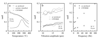
For the composite structures, these energy-cost phenomenon nearly disappeared as the BMI polymers made all the bundles adhered to each other and there no longer existed the so-called “interfaces” between different aggregation phases. At room temperature, the loss factor was even smaller than 0.05 for low-frequency vibrations (Figure 5c). However, due to the glass transition of polymer, the loss factor increased remarkably above 200 .
The high loss factor of the as-produced films (comparable to rubber) to makes it possible to develop new-type high damping materials, based on the arrangement-induced viscoelastic behavior xu.m:2010 , while the CNT/BMI composite films can be developed as superior structural materials to be used in aerospace, automotive, and other transportation industries.
Electrical properties. The ability to conduct electricity of a thin film is usually characterized by sheet resistance or square resistance, in units of “ohms per square”. The square resistance of the as-produced film was 1.194 , by using the four-point probe method. After being impregnated with BMI resins, the resistance decreased to 0.926 , owing to the densification effect. After being stretched, the CNT network was aligned and the connections between CNT bundles were separated by BMI resins. As a result, the resistance increased to 1.461 . The curing process finally fixed the composite structure where neither CNTs nor polymers aggregated, and the resistance further increased to 1.931 . By considering the final film thickness of 3 , the electrical conductivity was S , about 0.3% or 12% of copper’s or stainless steel’s electrical conductivity.
In summary, based on the unique properties of raw materials of CNTs and resins (entanglement, unaggregation, high plasticity, and low softening point) and the multi-step stretching method, we have been able to obtain a magic composite structure where neither CNTs nor polymers formed aggregated phases, a big step to approach the ideal composite structure that can fully utilize all the CNT surfaces in load transferring. The highest tensile strength was up to 6.94 GPa (or about 4.24 ), much higher than the strength of carbon fiber reinforced polymers. The CNT/BMI composite films also exhibited high ability to conduct electricity. As in such composite structure nearly all the surfaces of nanometer-sized components can be used, based on the bio-inspired aggregation control, we anticipate that the present fabrication method can be generalized for developing multifunctional and smart nanocomposites.
Methods. The CNTs were mainly double-walled and were synthesized with an injection chemical vapor deposition method li.yl:2004 . The grown CNTs formed a sock-like aerogel and were winded on a roller with the aid of ethanol densification to obtain 2D CNT films. The as-produced CNT films were impregnated by BMI resin/acetone solutions with designed CNT-to-resin mass ratios. The optimal CNT-to-resin mass ratio was about 7:3. Then the resin-impregnated films were stretched by more than 30% in length, in a multi-step way where sufficient structural relaxation was allowed after every step. The stretched films were cured according to the designed profile, namely, 140 for 0.5 h, 170 for 3 h, 220 for 2 h, and 250 for 3 h, with a pressure of 6–8 MPa.
Tensile tests were performed on an Instron 3365 Universal Test Machine (Instron Corp., Norwood, USA) at a strain rate of 0.5 . The film samples were cut into 2.5–3 cm0.5–2 mm pieces, and the gauge length was larger than 10 mm. Some tensile tests to show the processability were also performed on the “wet” films with a larger width of 5–10 mm.
Dynamic mechanical analysis was carried out with a Netzsch DMA 242E Analyzer (Netzsch-Gerätebau GmbH, Selb, Germany). Temperature-dependent loss factor () was measured in the temperature range of 30–400 at a heating rate of 10 and a vibration amplitude of 10 . Another scanning mode was performed where the vibration amplitude was tuned from 10 to 20 , at room temperature. The allowed vibration frequencies included 5, 10, 20, 50, and 100 Hz. The sample’s gauge length was 6 mm, corresponding to the dynamic vibration strain was 0.17%–0.33%.
Acknowledgements This work was supported in part by the National Natural Science Foundation of China (21273269, 11302241, 21473238, 51473171), International Science & Technology Cooperation Project of Jiangsu Province (BZ2011049), and Suzhou Industrial Science and Technology Program (ZXG201416).
Author contributions Y.H. fabricated the composite films and participated in the method design with X.Z. and Q.L.; X.Y. and J.Z. repeated all the experiments that Y.H. had performed; Y.H., X.Y., J.Z., and S.L. performed mechanical tests and structural characterizations; F.L. and T.Z. fabricated the resin molecules and assisted the fabrication of composite films; P.G. and Y.Z. performed the injection chemical vapor deposition and provided the raw CNT films; all authors provided information for manuscript writing and X.Z. wrote the manuscript with their helps.
References
- (1) Ha, T. L. B., Quan, T. M., Vu, D. N. & Si, D. M. Naturally Derived Biomaterials: Preparation and Application, in: Regenerative Medicine and Tissue Engineering (ed. Andrades, J. A.) Ch. 11, pp 247–274. (InTech - Open Access, Rijeka, Croatia 2013).
- (2) Giesa, T., Arslan, M., Pugno, N. M. & Buehler, M. J. Nanoconfinement of Spider Silk Fibrils Begets Superior Strength, Extensibility, and Toughness. Nano Lett. 11, 5038–5046 (2011).
- (3) Preston, C. M. & Sayer, B. G. What’s in a nutshell: an investigation of structure by carbon-13 cross-polarization magic-angle spinning nuclear magnetic resonance spectroscopy. J. Agric. Food Chem. 40, 206–210 (1992).
- (4) Porter, S. M. Seawater Chemistry and Early Carbonate Biomineralization. Science 316, 1302–1302 (2007).
- (5) Cheng, Q., Jiang, L. & Tang, Z. Bioinspired Layered Materials with Superior Mechanical Performance. Acc. Chem. Res. 47, 1256–1266 (2014).
- (6) Baughman, R. H., Zakhidov, A. A. & de Heer, W. A. Carbon Nanotubes – the Route Toward Applications. Science 297, 787–792 (2002).
- (7) Coleman, J. N., Khan, U., Blau, W. J. & Gun’ko, Y. K. Small but strong: A review of the mechanical properties of carbon nanotube-polymer composites. Carbon 44, 1624–1652 (2006).
- (8) Moniruzzaman, M. & Winey, K. I. Polymer Nanocomposites Containing Carbon Nanotubes. Macromolecules 39, 5194–5205 (2006).
- (9) Liu, L., Ma, W. & Zhang, Z. Macroscopic Carbon Nanotube Assemblies: Preparation, Properties, and Potential Applications. Small 7, 1504–1520 (2011).
- (10) Kong, L. & Chen, W. Carbon Nanotube and Graphene-based Bioinspired Electrochemical Actuators. Adv. Mater. 26, 1025–1043 (2014).
- (11) Coleman, J. N., Khan, U. & Gun’ko, Y. K. Mechanical Reinforcement of Polymers Using Carbon Nanotubes. Adv. Mater. 18, 689–706 (2006).
- (12) Fiedler, B., Gojny, F. H., Wichmann, M. H. G., Nolte, M. C. M. & Schulte, K. Fundamental aspects of nano-reinforced composites. Compos. Sci. Technol. 66, 3115–3125 (2006).
- (13) Xie, X.-L., Mai, Y.-W. & Zhou, X.-P. Dispersion and alignment of carbon nanotubes in polymer matrix: A review. Mater. Sci. Eng. R 49, 89–112 (2005).
- (14) Spitalsky, Z., Tasis, D., Papagelis, K. & Galiotis, C. Carbon nanotube-polymer composites: Chemistry, processing, mechanical and electrical properties. Prog. Polym. Sci. 35, 357–401 (2010).
- (15) Rahmat, M. & Hubert, P. Carbon nanotube-polymer interactions in nanocomposites: A review. Compos. Sci. Technol. 72, 72–84 (2011).
- (16) Zhang, M. et al. Strong, Transparent, Multifunctional, Carbon Nanotube Sheets. Science 309, 1215–1219 (2005).
- (17) Cheng, Q. et al. High Mechanical Performance Composite Conductor: Multi-Walled Carbon Nanotube Sheet/Bismaleimide Nanocomposites. Adv. Funct. Mater. 19, 3219–3225 (2009).
- (18) Cheng, Q., Wang, B., Zhang, C. & Liang, Z. Functionalized Carbon-Nanotube Sheet/Bismaleimide Nanocomposites: Mechanical and Electrical Performance Beyond Carbon-Fiber Composites. Small 6, 763–767 (2010).
- (19) Liu, W. et al. Producing superior composites by winding carbon nanotubes onto a mandrel under a poly(vinyl alcohol) spray. Carbon 49, 4786–4791 (2011).
- (20) Di, J. et al. Dry-Processable Carbon Nanotubes for Functional Devices and Composites. ACS Nano 6, 5457–5464 (2012).
- (21) Wang, X. et al. Ultrastrong, Stiff and Multifunctional Carbon Nanotube Composites. Mater. Res. Lett. 1, 19–25 (2013).
- (22) TORAYCA® carbon fibers T300 data sheet: http://www.toraycfa.com/pdfs/T300DataSheet.pdf.
- (23) Wagner, H. D. Nanocomposites: Paving the way to stronger materials. Nat. Nanotechnol. 2, 742–744 (2007).
- (24) Li, Y.-L., Kinloch, I. A. & Windle, A. H. Direct Spinning of Carbon Nanotube Fibers from Chemical Vapor Deposition Synthesis. Science 304, 276–278 (2004).
- (25) Zhang, M., Atkinson, K. R. & Baughman, R. H. Multifunctional Carbon Nanotube Yarns by Downsizing an Ancient Technology. Science 306, 1358–1361 (2004).
- (26) Li, Z., Yang, M., Huang, R., Zhang, M. & Feng, J. Bismaleimide resin modified with diallyl bisphenol A and diallyl p-phenyl diamine for resin transfer molding. J. Appl. Polym. Sci. 80, 2245–2250 (2001).
- (27) Xu, M., Futaba, D. N., Yumura, M. & Hata, K. Alignment Control of Carbon Nanotube Forest from Random to Nearly Perfectly Aligned by Utilizing the Crowding Effect. ACS Nano 6, 5837–5844 (2012).
- (28) Xu, M., Futaba, D. N., Yamada, T., Yumura, M. & Hata, K. Carbon Nanotubes with Temperature-Invariant Viscoelasticity from -196 to 1000C. Science 330, 1364–1368 (2010).
Supplementary Information
1. Preparation of entangled carbon nanotube films
The CNTs were synthesized by using an injection chemical vapor deposition (CVD) method \citesupps-li.yl:2004, where a mist of ethanol, ferrocene (2 wt%), and thiophene (1 vol%) was injected at a rate of 20–30 ml/h into a heated gas flow reactor (diameter 80 mm). A gas mixture of Ar (3500 sccm) and \ceH2 (4250 sccm) were also injected into the reactor tube as a carrier gas. The temperature in reaction region was set to 1300 . The grown CNTs formed a sock-like aerogel in the gas flow and were blown out with the carrier gas. The CNT aerogel was winded on a roller with the aid of liquid densification (ethanol was used here). By controlling the winding number, CNT films with a thickness ranging from 10–30 were finally obtained.
The basic structural units of the as-produced CNT films were small-sized CNT bundles, which usually had a diameter of 40–50 nm and contained about 50 CNTs. Once the ferrocene concentration or the injection rate is increased, larger-sized bundles can be obtained. By controlling the growth parameters, such as the concentration of ferrocene and growth temperature, it was possible to change the number of CNTs in a bundle and number of walls of individual CNT.
Raman spectra of the CNTs showed a high G to D-band intensity ratio (5), corresponding to a high level of crystallinity (Figure S1a). The Raman signals of radial breathing modes (RBMs) also indicated that there existed a large number of double-walled CNTs. Further, thermal gravimetric analysis showed that there was about 9 wt% mass left for the as-produced CNT films after being heated up to 800 in air (Figure S1b).
2. Entanglement after liquid treatment
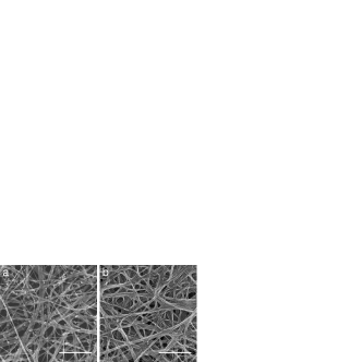
As discussed in the main text, the entanglement was not altered after liquid densification. Figure S2 shows two acetone-densified CNT networks. As compared to Figure 2a (in the main article), it is clear that the pore size had decreased from 500 nm to 100–200 nm, while the feature of random distribution and aggregation structure was maintained. The densification mainly took place along the direction perpendicular to the film surface, that is, different CNT layers (due to the winding process) were drawn closer, while the shrinkage of film width and length was less than 2–5% (but measurable). Therefore, it became possible to introduce resin molecules into the CNT films without aggregating the CNT bundles.
3. Mechanical properties of dry films
As the bismaleimide (BMI) resins had a softening point smaller than 60 and demonstrated a viscous liquid property, we call the resin-impregnated CNT films as “wet” films while the pure CNT films as dry ones. The tensile strength, strain at break, and toughness (the area covered under stress-strain curve) of the as-produced dry films were up to 180–198 MPa, 20–26%, and 32–37 MPa, respectively (Figure S3a). Stretching the dry films to align CNTs is the simplest method to improve the mechanical properties. By stretching directly by 20% within one minute and then maintaining the stretching to relax for 10–30 min, the films exhibited improved strengths and toughness, up to 492–620 MPa and 35–40 MPa, respectively. In the stretched film, CNTs became much more aligned (Figure S3b), making the modulus larger than 12 GPa.
It is important to notice that, during the stretching process the CNTs not only became aligned, but also aggregated to form large-size bundles (as labelled by arrows in Figure S3b). The aggregation can benefit the load transfer between CNTs in the stretched dry films, however, might become weak part in composite films by impregnating BMI resins and then curing them. This is because the aggregated CNTs transfer loads just depending on the intertube sliding friction while the BMI network can increase significantly the interfacial interactions with CNT surfaces and connect non-neighboring CNTs, resulting in much more efficient load transfer within polymer-bridged CNTs \citesupps-cheng.qf:2009, s-cheng.qf:2010, s-li.s:2012, s-wang.x:20131. This means, getting rid of CNT aggregation has become a challenge as important as improving interfacial interaction and CNT alignment. To further confirm the effect of aggregation, BMI resins were impregnated into the stretched dry films. As the aggregation existed, such CNT/BMI composite film exhibited a tensile strength up to only 585–801 MPa, after being cured.
4. High plasticity of “wet” films
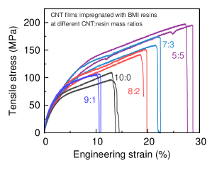
To avoid CNT aggregation, the as-produced CNT films were impregnated with 1 wt% BMI resin/acetone solutions prior to the stretching process. By controlling the total volume of solution, “wet” films at different CNT-to-resin mass ratios were produced, namely 9:1, 8:2, 7:3, and 5:5 (similarly, the ratio for dry films was 10:0). The “wet” films had different strain at break at different mass ratios (Figure S4). When a small amount of resins were impregnated, the resin molecules could not sufficiently cover the CNT surfaces and thus caused significant inhomogeneity within the film. Therefore the film became easier to fracture. When more resins were used, the film became more and more plastic and even can be stretched by 30%. This means that the wet environment gives the film enhanced processability.
Notice that the 10:0 sample had a different strain at break from the tensile tests shown in Figure S3a. This is because the widths of the test samples were 10 and 2 mm for the samples in Figure S4 and S3, respectively. As compared to small samples, assembly defects (in the as-produced CNT network) make the fracture easier for large ones. In fact, the tensile results of large samples reflected the real processability, as the resin impregnation and stretching processes were performed on CNT films with a width of 1 cm.
5. Low-softening-point bismaleimide resins
The low-softening-point BMI (l-BMI) resins were synthesized by modifying traditional BMI monomers with diallyl bisphenol A (DBA) \citesupps-li.zm:2001. Besides the DBA modification, the original molecular structure of BMI monomers also determines remarkably on the softening dynamics. As a comparison study, the DBA-modified resins with larger molecular weight of monomers, higher molecular rigidity, and thus higher softening point, the h-BMI resins, were also used to show their influences on the processability of CNT/BMI composite films. Rheological measurement, the viscosity-temperature relationship, reveals that the viscosity of l-BMI decreased to below 20 at 58 while such temperature was 80 for h-BMI (Figure S5a). By impregnating them into CNT films at the same mass ratio of 7:3, the tensile measurements showed different increase in strain at break. The CNT/h-BMI “wet” film fractured at 15% while the CNT/l-BMI at more than 22% (Figure S5b, sample width 10 mm).
6. One-step and multi-step stretching methods
The stretching methods are schematically shown in Figure 3 in the main text. Here we provide more details about the difference between the one-step and multi-step treatments.
The as-produced CNT films are first impregnated by BMI resin/acetone solution. As acetone has a high infiltration ability into CNT assemblies, the impregnation can easily make all the CNT bundles surrounded by the resin molecules and avoid the aggregation of CNTs. “Wet” films containing a designed CNT-to-resin mass ratio are prepared by using the low-softening-point resins. These “wet” films can be directly stretched by 20% in a one-step way. The one-step stretching can effectively align the CNTs, however, as the lack of relaxation during the stretching, the entangled or cross-linked segments can not be fully aligned and thus hinder the densification process.
A multi-step stretching method is used to introduce the relaxation process. In this way, the “wet” film is always stretched slightly in each step, by 2–3%, and there are 5–10 minutes to relax the film before the next stretching. If the stretching magnitude depends on the current film length, after steps, the total stretching magnitude can be calculated by . (The stretching magnitude can be confirmed by the final length increase as compared to the original length.) If the stretching length is always fixed, the total stretching magnitude is then where is the original film length.
The relaxation process plays important roles in optimizing CNT alignment and level of densification for the “wet” films, which can be represented by the mechanical properties of the cured samples and the mass density as well.
7. Mechanical properties of one-step stretched films after curing at mass ratio of 7:3
The “wet” films were cured by a hot-pressing process with a pressure of 6–8 MPa. The curing profile was 140 for 0.5 h, 170 for 3 h, 220 for 2 h, and 250 for 3 h. The introduction of 140 treatment was found to be also important to liquidize the resin molecules and further improved homogeneity in the composite structure.
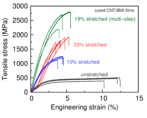
The one-step stretching was applied by 10% and 20%, respectively, on “wet” films with the CNT-to-resin mass ratio of 7:3. After being cured, the two stretched composite films exhibited tensile strengths of 1.12–1.24 GPa and 1.74–1.92 GPa, respectively, while the unstretched composite films had strengths less than 500 MPa (Figure S6). This can be ascribed to the insufficient alignment of CNTs. Furthermore, as compared to the multi-step stretching, the lack of relaxation process resulted in inhomogeneity in the composite structure. For example, when the “wet” films were stretched by 19% in the multi-step way, there should not be a significant difference in alignment as compared to the 20% one-step stretched films. However, the inhomogeneity in one-step stretched films reduced the efficiency of load transfer between CNT bundles and thus hindered the increase in elastic modulus. As a result, their tensile strengths of 2.19–2.79 GPa were much larger, at least by 450–870 MPa.
8. Effect of multi-step stretching
In the multi-step stretching, we set and the relaxation time to be 10 min, and thus the total stretching magnitude was . The maximum number of steps differed from sample to sample. For the 7:3 “wet” film while for the 8:2 film . We also tried to stretch the film by a fixed length of 1 mm in each step (the original length and width was about 35 mm and 10 mm, respectively). However, we did not observe any difference between these two treatments. To further increase the maximum stretching magnitude, studies should be performed on the CVD process where the CNT structure and formation of CNT network are determined.
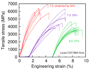
Figure S7 shows the stress-strain curves of cured CNT/BMI films after being multi-step stretched. The highest performance was found for the 7:3 films being stretched by 34% (). The tensile strengths and moduli (both in units of GPa) of these tests were 6.940/284.2, 6.438/314.9, 6.265/299.0, 5.907/350.6, 5.842/246.8, and 5.773/211.9, respectively. Even just being stretched up to 25%, the tensile strength was still found to range from 3.83 to 6.31 GPa, higher than traditional carbon fiber/epoxy composites and recently reported high performance CNT/BMI composites \citesupps-cheng.qf:2009, s-cheng.qf:2010, s-wang.x:20131.
As compared to the 7:3 mass ratio, the 8:2 ratio resulted in a maximum stretching magnitude of 27% and final tensile strengths ranging from 3.42 to 4.65 GPa. This means that for high performance composites based on polymer impregnation into CNT assemblies, the polymer content should be around 30 wt%. When more BMI were introduced into the film, like mass ratios of 6:4 and 5:5, the BMI aggregation appeared and became structural defects to make the film more brittle than the 7:3 or 8:2 ones.
9. Herman’s orientation factor
Herman’s orientation factor (HOF) is a commonly used parameter to characterize orientation and has been successfully used for determining the alignment level for CNT arrays \citesupps-xu.m:2012. It takes the value 1 for a system with perfect orientation parallel to a reference direction, and zero for completely nonoriented samples. The calculation of HOF is based on the intensity profile of orientation angle between the structural unit vector and the reference direction, according to its definition
| (1) |
where
| (2) |
Here the intensity profile was obtained by using the ‘Orientation’ property of ‘regionprops’ in Matlab, where an SEM image should be first converted to be strongly contrasted.

Figure S8 shows the different intensity profiles for the as-produced CNT film, directly stretched CNT film, and the super-strong CNT/BMI composite film, respectively. The reference direction was taken to be the horizontal line for each image. For the original film, the orientation within [-5,5] was only 9.2% in the total counting of the orientation angles. After being stretched, the [-5,5] fraction increased up to 63.0% and 74.5%. However, as the stretching magnitude for the one-step stretching was only 20% in length, there were still some orientation angles larger than 40 (6.6% in the angle counting). According to these profiles, the HOFs were 0.209, 0.632, and 0.816, respectively. Obviously, the CNT alignment was significantly improved after the one-step and multi-step stretching treatments.
10. Fracture morphology
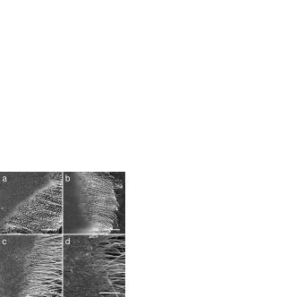
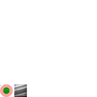
Figure S9 shows fracture morphologies of CNT/BMI composite films (mass ratio 7:3). Pull-out mechanism dominated at the fracture and the length of bare CNTs (more than 20 ) can be used to estimate the tensile strength by (see the schematic shown in Figure S10a), , , and being the interfacial shear strength between CNT and BMI, diameter of CNT bundle, and bare length at fracture. Here we assumed that the CNT bundles were separated from each other by a distance close to the bundle size, and the space between them was filled by BMI polymers. By using 30 MPa, nm, and , the strength was estimated to be 12 GPa, in nice agreement with experimental measurements.
TEM characterization confirmed that the BMI thickness was in the same order of magnitude with the bundle size (Figure S10b). According to the strength estimation of , to further improve the mechanical performance, the interfacial enhancement and reduction in bundle size will be the two major solutions.
Furthermore, from Figure S9d one can find that the CNT bundles were clearly unaggregated and the BMI polymers did not aggregate but uniformly distributed between the bundles.
11. Film thickness and specific tensile strength
The calculation of tensile strength requires the information of film width and thickness. The thickness of as-produced dry films was controlled to be within 10–30 . As the impregnated BMI resins occupied the pores in film, there was no thickness increase for the “wet” films. After being stretched, one-step or multi-step, the thickness decreased significantly with the stretching magnitude.

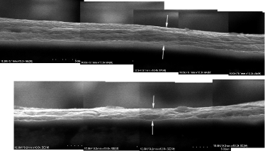
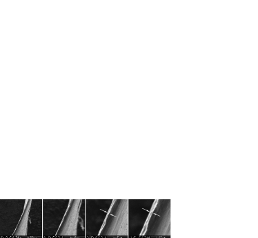
Figure S11 shows thicknesses of four stretched and cured composite films, with stretching magnitude ranged from 20% to 34% (from up to bottom). The final thicknesses was measured to be 5, 2.8, 2, and 1.7 , respectively. To avoid overestimation, we did not use the thickness of the thinnest segment to calculate the tensile strength, but the measurement on the thickest segment. For example, the thickness of the 34% stretched film was 2.5–3 .
As discussed in the main text, one can calculate the specific strength by measuring the fracture force and mass density of the CNT/BMI composite films. For the multi-step stretched films by 25%, the total mass for a 2 cm1 cm sample was 1.15 mg, corresponding to an area density of 0.58 mg/cm2. The total force to fracture such film was about 16.5 N/mm in average (Figure S12), and thus the specific strength (by dividing the force per width by the area density) was 2.87 N/tex. When the stretching magnitude was improved to 34%, the fracture force per width was 19.5 N/mm, the area density decreased slightly to 0.46 mg/cm2, and the specific strength was 4.24 N/tex. As the mass density was about 1.55 g/cc, the product of specific strength and volumetric density was 6.57 GPa. This means that all the measured data, including the force, film thickness, and mass density were completely consistent.
12. Summary
We provide here detailed information of CNT growth, BMI resins, and impregnation and stretching techniques. Based on the unique properties of raw materials (entanglement, unaggregation, high plasticity, and low softening point) and the multi-step stretching method which was applied on resin-impregnated CNT films, we have been able to obtain a magic composite structure where neither CNTs nor polymers formed aggregated phases, a big step to approach the ideal composite structure to fully utilize all the CNT surfaces in load transferring. The highest tensile strength was 6.94 GPa (or 4.24 N/tex), much higher than the strength of carbon fiber reinforced polymers. The CNT/BMI composite films also exhibited high ability to conduct electricity.
References
- (1) Y.-L. Li, I. A. Kinloch, A. H. Windle, Science 2004, 304, 276.
- (2) Q. Cheng, J. Bao, J. Park, Z. Liang, C. Zhang, B. Wang, Adv. Funct. Mater. 2009, 19, 3219.
- (3) Q. Cheng, B. Wang, C. Zhang, Z. Liang, Small 2010, 6, 763.
- (4) S. Li, X. Zhang, J. Zhao, F. Meng, G. Xu, Z. Yong, J. Jia, Z. Zhang, Q. Li, Compos. Sci. Technol. 2012, 72, 1402.
- (5) X. Wang, Z. Z. Yong, Q. W. Li, P. D. Bradford, W. Liu, D. S. Tucker, W. Cai, H. Wang, F. G. Yuan, Y. T. Zhu, Mater. Res. Lett. 2013, 1, 19.
- (6) Li, Z., Yang, M., Huang, R., Zhang, M., and Feng, J. J. Appl. Polym. Sci. 80(12), 2245–2250 (2001).
- (7) Xu, M., Futaba, D. N., Yumura, M., and Hata, K. ACS Nano 6(7), 5837–5844 (2012).