myctr
ControlIt! - A Software Framework for Whole-Body Operational Space Control
Abstract
Whole Body Operational Space Control (WBOSC) is a pioneering algorithm in the field of human-centered Whole-Body Control (WBC). It enables floating-base highly-redundant robots to achieve unified motion/force control of one or more operational space objectives while adhering to physical constraints. Although there are extensive studies on the algorithms and theory behind WBOSC, limited studies exist on the software architecture and APIs that enable WBOSC to perform and be integrated into a larger system. In this paper we address this by presenting ControlIt!, a new open-source software framework for WBOSC. Unlike previous implementations, ControlIt! is multi-threaded to increase servo frequencies on standard PC hardware. A new parameter binding mechanism enables tight integration between ControlIt! and external processes via an extensible set of transport protocols. To support a new robot, only two plugins and a URDF model needs to be provided — the rest of ControlIt! remains unchanged. New WBC primitives can be added by writing a Task or Constraint plugin. ControlIt!’s capabilities are demonstrated on Dreamer, a 16-DOF torque controlled humanoid upper body robot containing both series elastic and co-actuated joints, and using it to perform a product disassembly task. Using this testbed, we show that ControlIt! can achieve average servo latencies of about 0.5ms when configured with two Cartesian position tasks, two orientation tasks, and a lower priority posture task. This is significantly higher than the 5ms that was achieved using UTA-WBC, the prototype implementation of WBOSC that is both application and platform-specific. Variations in the product’s position is handled by updating the goal of the Cartesian position task. ControlIt!’s source code is released under an LGPL license and we hope it will be adopted and maintained by the WBC community for the long term as a platform for WBC development and integration.
keywords:
Software Framework; Whole Body Control; Whole Body Operational Space Control; Upperbody Humanoid Robot1 Introduction
Whole Body Control (WBC) takes a holistic view of a multi-branched highly redundant robot like humanoids to achieve general coordinated behaviors. One of the first WBC algorithms is Whole Body Operational Space Control (WBOSC) [1, 2, 3], which provides the theoretical foundations for achieving operational space inverse dynamics, task prioritization, free floating degrees of freedom, contact constraints, and internal forces. There is now a growing community of researchers in this field as exemplified by the recent formation of an IEEE technical committee on WBC [4]. While the foundational theory and algorithms behind WBC have recently made great strides, less progress exists in software support, limiting the use of WBC today. In this paper, we remedy this problem by presenting ControlIt!,111ControlIt! should not be associated with MoveIt! [5]. ControlIt! is primarily focused on whole body feedback control whereas MoveIt! is primarily focused on motion planning. Thus, MoveIt! and ControlIt! typically reside at different levels of a robot application’s software stack. The default feedback controller used by MoveIt! is ros_control [6]. However, MoveIt! could be configured to work with ControlIt! instead of ros_control if needed. an open source222The source code for ControlIt! is available under a LGPLv2.1 license. Instructions for downloading and using it are available at https://robotcontrolit.com software framework for WBOSC.
In this paper, we introduce ControlIt!, a software framework that enables WBOSC controllers to be instantiated and is designed for systems integration, extensibility, high performance, and use by both WBC researchers and the general public. Instantiating a WBOSC controller consists of defining a prioritized compound task that defines the operational space objectives and lower priority goal postures that the controller should achieve, and a constraint set that specifies the natural physical constraints of the robot. Systems integration is achieved through a parameter binding mechanism that enables external processes to access WBOSC parameters through various transport layers, and a set of introspection tools for gaining insight into the controller’s state at runtime. ControlIt! is extensible through the use of plugins that enable the addition of new WBC primitives and support for new robot platforms. High performance is achieved by using state-of-the-art software libraries and multiple-threads that enable ControlIt! to offer higher servo frequencies relative to previous WBOSC implementations. By making ControlIt! open source and maintaining a centralized website (https://robotcontrolit.com) with detailed documentation, installation instructions, and tutorials, ControlIt! can be modified to evaluate new WBC ideas and supported long term.
The intellectual merit and key contributions of this paper are as follows:
-
1.
We design a software architecture for supporting general use of WBOSC and its integration within a larger system via parameter binding and events.
-
2.
We introduce the first API based on WBOSC principles for use across general applications and robots.
-
3.
We provide an open-source software implementation.
-
4.
We design and implement a high performance multi-threaded architecture that increases the achievable servo frequency by 10X relative to previous implementations of WBOSC.
-
5.
We reduce the number of components that need to be modified to develop a new behavior to the set of RobotInterface, ServoClock, CompoundTask, ConstraintSet and decouple these changes from core ControlIt! code via dynamically loadable plugins.
-
6.
We demonstrate ControlIt!’s utility and performance using a humanoid robot executing a product disassembly task.
The remainder of this paper is organized as follows. Section 2 discusses related work. Section 3 provides an overview of WBOSC’s mathematical foundations. Section 4 presents ControlIt!’s software architecture and APIs. Section 5 presents how ControlIt! was integrated with Dreamer and used to develop a product disassembly task. Section 6 contains a discussion on other experiences using ControlIt! and future research directions. The paper ends with conclusions in Section 7.
2 Related Work
As a field, WBC is rapidly evolving. Most algorithms issue torque commands [7, 8, 9, 10, 11, 12, 13, 14, 15, 16, 17, 18, 19, 20, 21, 22, 23, 24, 25]. They differ in whether they are centralized [26, 27] or distributed [28, 29], focus on manipulation [30], locomotion [31, 32, 33], or behavior sequencing [34, 35], the underlying control models used [36, 37, 38], and whether they’ve been evaluated in simulation or on hardware [39, 40, 41, 42, 43, 44, 45, 46, 47, 48, 49, 50, 51, 52, 53, 54, 55, 56, 57, 58, 59, 60, 61, 62, 63, 64, 65, 66, 67]. These efforts demonstrate the behaviors enabled by WBC such as the use of compliance, multi-contact postures, robot dynamics, and joint redundancy to balance multiple competing objectives. ControlIt! is currently focused on supporting general use of WBOSC and its capabilities, but may be enhanced to include ideas and capabilities from these recent WBC developments.
An implementation of WBOSC called Stanford-WBC [68] was released in 2011. Stanford-WBC includes mechanisms for parameter reflection, data logging, and script-based configuration, but was a limited implementation of WBOSC that did not support branched robots, mobile robots, or contact constraints. It was used to make Dreamer’s right arm wave and shake hands. More recently, UTA-WBC extended Stanford-WBC to support the full WBOSC algorithm, which includes branched robots, free floating degrees of freedom, contact constraints, and a more accurate robot model that includes rotor inertias [69]. UTA-WBC was used to make a wheeled version of Dreamer containing 13 DOFs maintain balance on rough terrain. While this demonstrated the feasibility of WBOSC using a real humanoid robot, UTA-WBC was a research prototype targeted for a specific robot and specific behavior, i.e., balancing [27]. The implementation was not designed to work as part of a larger system for general applications. Instead, ControlIt! is a complete software re-design and re-implementation of the WBOSC algorithm with a focus on the software constructs and APIs that facilitate the integration of WBOSC into larger systems.
The differences between UTA-WBC and ControlIt! are shown in Table 1. Compared with UTA-WBC and Stanford-WBC, ControlIt! is a complete re-implementation that does not build upon but rather replaces the previous implementation. Specifically, ControlIt! contains new and more expressive software abstractions that enable arbitrarily complex WBOSC controllers to be configured, works with newer software libraries, middleware, and simulators, supports extensibility through a plugin-based architecture, is multi-threaded, and is designed to easily integrate with external processes through parameter binding and controller introspection mechanisms.
| Property | UTA-WBC | ControlIt! |
|---|---|---|
| OS | Ubuntu 10.04 | Ubuntu 12.04 and 14.04 |
| ROS Integration | ROS Fuerte | ROS Hydro and Indigo |
| Linear Algebra Library | Eigen 2 | Eigen 3 |
| Model Library | Tao | RBDL 2.3.2 |
| Model Description Format | Proprietary XML | URDF |
| Integration (higher levels) | N/A | Parameter binding |
| Integration (lower levels) | Proprietary | RobotInterface and ServoClock plugins |
| Controller Introspection | Parameter Reflection | Parameter Reflection and ROS Services |
| WBC Initial Configuration | YAML | YAML and ROS parameter server |
| WBC Reconfiguration | N/A | Enable / disable tasks and constraints, update task priority levels |
| Key Abstractions | task, constraint, skill | Compound task, constraint set |
| Task / Constraint Libraries | Statically coded | Dynamically loadable via ROS pluginlib |
| Number of threads | 1 | 3 |
| Simulator | Proprietary | Gazebo 5.1 |
| Website | https://github.com/lsentis/uta-wbc-dreamer | https://robotcontrolit.com |
The ability to integrate with external processes is important because applications of branched highly-redundant robots of the type targeted by WBC are typically very sophisticated involving many layers of software both above and below the whole body controller. To handle such complexity, a distributed component-based software architecture is typically used where the application consists of numerous independently-running software processes or threads that communicate over both synchronous and asynchronous channels [70, 71]. The importance of distributed component-based software for advanced robotics is illustrated by the number of recently developed middleware frameworks that provide it. They include OpenHRP [72, 73], RT-Middleware [74], Orocos Toolchain [75], YARP [76], ROS [77, 78], CLARAty [79, 80], aRD [81], Microblx [82, 83], OpenRDK [84, 85, 86], and ERSP [87]. Among these, ControlIt! is currently integrated with ROS and is a ROS node within a ROS network, though usually as a real-time process potentially within another component-based framework (i.e., ControlIt!’s servo thread was an Orocos real-time task during the DRC Trials, and is a RTAI [88] real-time process in the Dreamer experiments discussed in this paper). In general, ControlIt! can be modified to be a component within any of the other aforementioned component-based robot middleware frameworks.
ControlIt! is designed to interact with components both below (i.e., closer to the hardware) and above (i.e., closer to the end user or application) it within a robotic system. Components below ControlIt! include robot hardware drivers or resource allocators like ros_control [6, 89] and Conman [90] that manage how a robot’s joints are distributed among multiple controllers within the system. This is necessary since multiple WBC controllers may coexist and a manager is needed to ensure only one is active at a time. In addition, joints in a robots’ extremity like those in an end effector usually have separate dedicated controllers. Components that may reside above ControlIt! include task specification frameworks like iTaSC [91, 92, 93, 94], planners like MoveIt! [5], management tools like Rock [95], MARCO [96], and GenoM [97], behavior sequencing frameworks like Ecto [98] and RTC [99], and other frameworks for achieving machine autonomy [100, 101, 102, 103, 104, 105, 106, 107]. Clearly, the set of components that ControlIt! interacts with is large, dynamic, and application-dependent. This is possible since component-based architectures provide sufficient decoupling to allow these external components to change without requiring ControlIt! to be modified.
3 Overview of Whole Body Operational Space Control
This section provides a brief overview of WBOSC. Details are provided in previous publications [1, 2, 3, 27]. Let be the number of actual DOFs in the robot. The robot’s joint state is represented by the vector as shown by the following equation.
| (1) |
The robot’s global pose is represented by a 6-dimensional floating virtual joint that connects the robot’s base link to the world, i.e., three rotational and three prismatic virtual joints. It is denoted by vector . The two partial state vectors, and , are concatenated into a single state vector . This combination of real and virtual joints into a single vector is called the generalized joint state vector. Let be the number real and virtual DOFs in the model that is used by WBOSC. Thus, .
The underactuation matrix defines the relationship between the actuated joint vector and the full joint state vector as shown by the following equation.
| (2) |
Let be the robot’s generalized joint space inertia matrix, be the generalized joint space Coriolis and centrifugal force vector, be the generalized joint space gravity force vector, be the contact Jacobian matrix that maps from generalized joint velocity to the velocity of the constraint space dimensions, be the co-state of the constraint space reaction forces, and be the desired force/torque joint command vector that is sent to the robot’s joint-level controllers. The robot dynamics can be described by a single linear second order differential equation shown by the following equation.
| (3) |
Constraints are formulated as follows. Let be the velocity of the constrained dimensions, which we approximate as being completely rigid and therefore yielding zero velocity on the contact points, as shown by the following equation.
| (4) |
Tasks are formulated as follows. Let be the desired velocity of the task, be the Jacobian matrix of task that maps from generalized joint velocity to the velocity of the task space dimensions, and be the generalized null-space of the constraint set. Furthermore, let be the contact consistent reduced Jacobian matrix [2] of task , i.e., it is consistent with and . The definition of is given by the following equation where operator is the dynamically consistent generalized inverse of .
| (5) | |||||
Let be the contact-consistent prioritized task-space inertia matrix [2] for task , be the reference, i.e., desired, task-space acceleration for task , be the contact-consistent task-space Coriolis and centrifugal force vector for task , and be the contact-consistent task space gravity force vector for task . The force/torque command of task , denoted , is given by the following equation.
| (6) |
To achieve multi-priority control, let be the Jacobian matrix of task that is consistent with , , and all higher priority tasks. The equation for is the sum of all of the individual task commands multiplied by the corresponding matrix as shown by the following equation.
| (7) |
Finally, when a robot has more than one point of contact with the environment, there are internal tensions within the robot. By definition, these “internal forces” are orthogonal to joint accelerations, i.e., they result in no net movement of the robot. The control structures like the multicontact/grasp matrix that are used to control these internal forces are documented in previous publications [3]. Let be the nullspace of and be the reference (i.e., desired) internal forces vector. The contribution of the internal forces can thus be added to Equation (7) as shown by the following equation.
| (8) |
4 ControlIt! Software Architecture
There are six guiding principles behind ControlIt!’s development: (i) separate concerns into interface definitions, implementations, and configuration, (ii) support extensibility and platform-independence through dynamically loadable plugins, (iii) encourage code reuse through plugin libraries, (iv) support systems integration through parameter binding, events, data introspection services, and compatibility with a modern software ecosystem, (v) be cognizant of performance and real- time considerations, and (vi) support two types of end users: developers who use ControlIt! and researchers who modify ControlIt!.
Section 4.1 contains a discussion of ControlIt!’s software architecture, which describes the software components within ControlIt’s core. Many of these components either instantiate plugins or are implemented by plugins. The use of plugins enables ControlIt! to be extensible in terms of supporting different robots and applications. Section 4.2 discusses mechanisms for configuring and integrating ControlIt! into a larger system. This includes the parameter reflection, binding, and event signaling mechanisms, and YAML specification files. Finally, a description of ControlIt!’s multi-threaded architecture is discussed in section 4.3.
4.1 Software Architecture
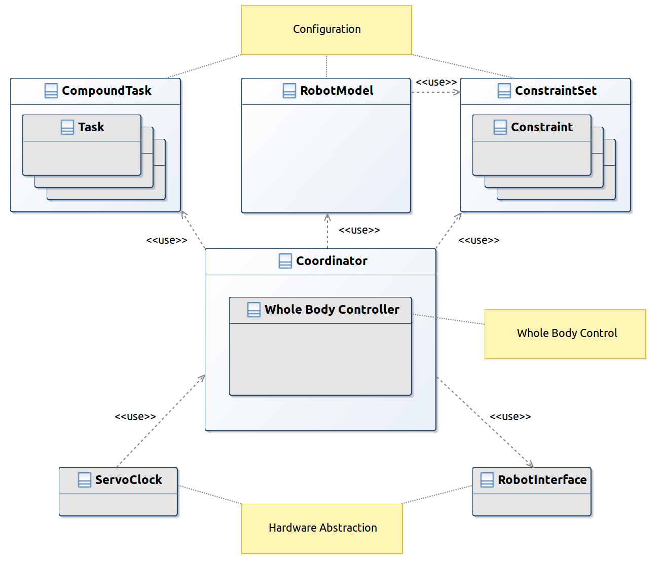
The software abstractions that enable ControlIt! to instantiate and integrate general WBOSC controllers are shown in Figure 1. The abstractions that are extendable via dynamically loadable plugins are colored gray. They include tasks, constraints, the whole body controller, the servo clock, and the robot interface. Non-extensible components include the compound task, robot model, constraint set, and coordinator. The coordinator implements the servo loop and uses all of the other abstractions except for the servo clock, which implements the servo thread and controls when the coordinator executes the next cycle of the servo loop. The software abstractions can be divided into three general categories: configuration, whole body control, and hardware abstraction.
Configuration. Configuration software abstractions include the robot model, compound task, and constraint set. Their APIs and attributes are shown in Figure 2. The robot model determines the kinematic and dynamic properties of the robot and builds upon the model provided by the Rigid Body Dynamics Library (RBDL) [108], which includes algorithms for computing forward and inverse kinematics and dynamics and frame transformations. The kinematic and dynamic values provided by the model are only estimates and may be incorrect, necessitating the use of a whole body feedback controller. The robot model API includes methods for saving and obtaining the joint state and getting properties of the robot like the joint space inertia matrix and gravity compensation vector. There are also methods for obtaining the joint order within the whole body controller. A reference to the constraint set is kept within the robot model to determine which joints are virtual (i.e., the 6-DOF free floating joints that specify a mobile robot’s position and orientation within the world frame), real, and actuated.
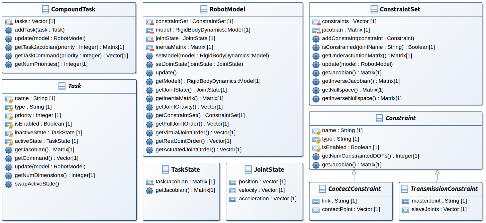
The compound task and constraint set contain lists of tasks and constraints, respectively. Tasks and constraints are abstract; concrete implementations are added to ControlIt! through plugins. Both have names and types for easy identification and can be enabled or disabled based on context. A task represents an operational or postural objective for the whole body controller to achieve. Concrete task implementations contain goal parameters that, in combination with the robot model, produce an error. The error is used by a controller inside the task to generate a task-space effort command333We use the word “effort” to denote generalized force, i.e., force or torque., which is accessible through the getCommand() method and may be in units of force or torque. In addition to the command, a task also provides a Jacobian that maps from task space to joint space. The compound task combines the commands and Jacobians of the enabled tasks and relays this information to the whole body controller. Specifically, for each priority level, the compound task vertically concatenates the Jacobians and commands belonging to the tasks at the priority level. The WBOSC algorithm uses these concatenated Jacobian and command matrices to support task prioritization and multiple tasks at the same priority level.
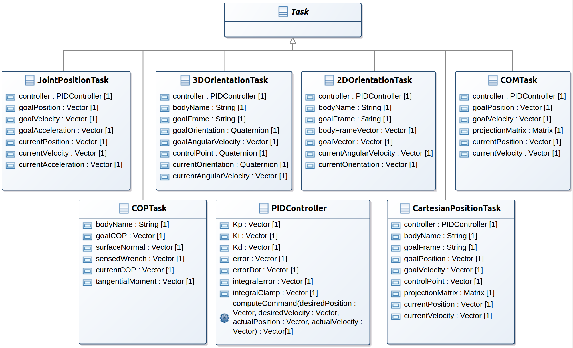
Task Library. To encourage code reuse and enable support for basic applications, ControlIt! comes with a task library containing commonly used- tasks. The tasks within this library are shown in Figure 3. There are currently six tasks in the library: joint position, 2D / 3D Orientation, center of mass, Cartesian position, and center of pressure. In the future, more tasks can be added to the library by introducing additional plugins. Of these, the joint position, orientation, and Cartesian position tasks have been successfully tested in hardware. The rest have only been tested in simulation. Note that all of the tasks make use of a PIDController. This feedback controller generates the task-space command based on the current error and gains. Alternative types of controllers like sliding mode control may be provided in the future.
The joint position task directly specifies the goal positions, velocities, and accelerations of every joint in the robot. It typically defines the desired “posture” of the robot, which is not an operational space objective but accounts for situations where there is sufficient redundancy within the robot to result in non-deterministic behavior when no posture is defined. Specifically, a posture task is necessary when the null space of all higher priority tasks and constraints is not nil, and the best practice is to always include one as the lowest priority task in the compound task. The joint position task has an input parameter called goalAcceleration to enable smooth transitions between joint positions. The goal acceleration is a desired acceleration that is added as a feedforward command to the control law. The currentAcceleration output parameter is a copy of the goalAcceleration parameter and is used for debugging purposes.
The 2D and 3D orientation tasks are used to control the orientation of a link on the robot. They differ in terms of how the orientations are specified. Whereas the 2D orientation is specified by a vector in the frame of the body being oriented, the 3D orientation is specified using a quaternion. The purpose of providing a 2D orientation task even though a 3D orientation could be used is to reduce computational overhead when only two degrees of orientation control is required. For example, a 2D orientation task is used to control the heading of Trikey, a 3 wheeled holonomic mobile robot, as shown in Figure 18, whereas a 3D orientation task is used to control the orientation of Dreamer’s end effectors, as shown in Figure 19(b). Visualizations of these two task-level controllers are given in C. The 2D orientation task does not include a goalAngularVelocity input parameter because its current implementation assumes the goal velocity is always zero. This assumption can be easily removed in the future by modifying the control law to include a non-zero goal velocity.
The Center Of Mass (COM) task controls the location of the robot’s COM, which is derived from the robot model. It is useful when balancing since it can ensure that the robot’s configuration always results in the COM being above the convex polygon surrounding the supports holding the robot up. The Center Of Pressure (COP) task controls the center of pressure of a link that is in contact with the ground. It is particularly useful for biped robots containing feet since it can help ensure that the COP of a foot remains within the boundaries of the foot thereby preventing the foot from rolling. The Cartesian position task controls the operational space location of a point on the robot. Typically, this means the location of an end effector in a frame that is specified by the user and is by default the world frame. For example, it is used to position Dreamer’s end effectors in front of Dreamer as shown in Figure 19. As indicated by the figure, multiple Cartesian position tasks may exist within a compound task, as long as they control different points on the robot.
As previously mentioned, the aforementioned tasks are those that are currently included with ControlIt!. They are implemented as plugins that are dynamically loaded on-demand during the controller configuration process. Additional tasks may be added in the future. For example, an external force task may be added that controls a robot to assert a certain amount of force against an external obstacle. In addition, an internal force task may be added to control the internal tensions between multiple contact points. A prototype of such a task was successfully used during NASA JSC DRC critical design review444As a Track A DRC team, NASA JSC was required to undergo a critical design review by DARPA officials in June 2013, which was in the middle of the period leading up to the DRC Trials in December 2013. The results of the review determined whether the team would continue to receive funding and proceed to compete in the DRC Trials as a Track A team. NASA JSC was one of six Track A teams to pass this critical design review. to make Valkyrie to walk in simulation, as shown in C, but is not included in the current task library due to the need for additional testing and refinement. For the walking behavior, ControlIt!’s compound task included a COM Task, internal tensions task, posture task, and, for each foot, a COP, Cartesian position, and orientation task.
Constraints. A constraint specifies natural physical limits of the robot. There are two types of constraints: ContactConstraint and TransmissionConstraint. Contact constraints specify places where a robot touches the environment. Transmission constraints specify dependences between joints, which occur when, for example, joints are co-actuated. The parent Constraint class includes methods for obtaining the number of DOFs that are constrained and the Jacobian of the constraint. Contact constraints have a getJoint() method that specifies the parent joint of the link that is constrained. Transmission constraints have a master joint that is actuated and a set of slave joints that are co-actuated with the master joint. Unlike tasks, constraints do not have commands since they simply specify the nullspace within which all tasks must operate. Like the compound task, the constraint set computes a Jacobian that is the vertical concatenation of all the constraint Jacobians. In addition, it provides an update method that computes both the null space projector and (defined in Equation (5)), accessors for these matrices, and methods for determining whether a particular joint is constrained. The whole body controller uses this information to ensure all of the constraints are met. While it is true that contact constraints are mathematically similar to tasks without an error term, we wanted to distinguish between the two since they serve significantly different purposes: tasks denote a user’s control objectives while constraints denote a robot’s physical limits. We did not want to confuse the API by using the same software abstraction for both purposes. Furthermore, by separating tasks and constraints, the API will be easier to extend to support optimization based controllers with inequality constraints.
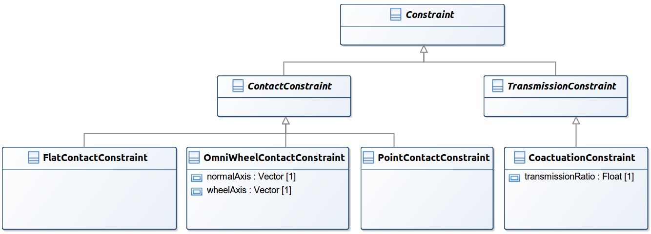
Constraint Library. Constraints included in ControlIt!’s constraint library are shown in Figure 4. Contact constraints include the flat contact constraint, omni wheel contact constraint, and point contact constraint. The flat contact constraint restricts both link translation and rotation. The omni wheel contact constraint restricts one rotational DOF and one translational DOF based on the current orientation of the wheel. Point contact constraint restricts just link translation. One transmission constraint called CoactuationConstraint is provided that enables ControlIt! to handle robots with two co-actuated joints, like the torso pitch joints in Dreamer. It includes a transmission ratio specification to handle situations where the relationship between the master joint and slave joint is not one-to-one. Currently only the two-joint co-actuation case is supported, though a more generalized constraint that supports more than two co-actuated joints could be trivially added in the future. Specifically, another child class of TransmissionConstraint can be added as a plugin to support the co-actuation of more than two joints by adding more rows to the constraint’s Jacobian. Like the task library, the constraint library can easily be extended with new constraints via the plugin mechanism used by ControlIt!.
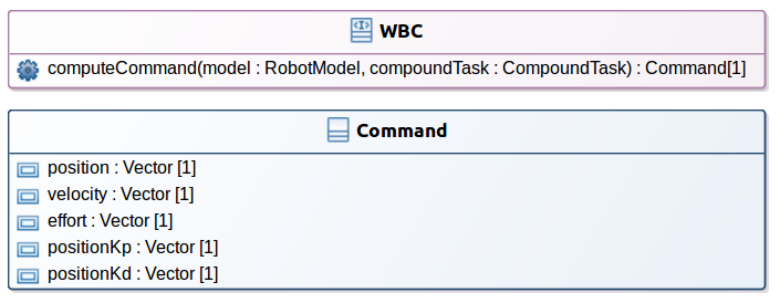
Whole body control. The class diagrams for the whole body control software abstractions are shown in Figure 5. There are two classes: WBC and Command. WBC is an interface that contains a single computeCommand() method. This method takes as input the robot model, which includes the constraint set, and the compound task. It performs the WBC computations that generate a command for each joint under its control and returns it within a Command object. The Command object specifies the desired position, velocity, effort, and position controller gains. Note that not all of these variables need to be used. For example, a robot that is purely effort controlled will only use the effort command. The optional fields within the command are included to support robots with joints that are position or impedance controlled.
The whole body controller within ControlIt! is dynamically loaded as a plugin using ROS pluginlib [109]. Two plugins are currently available as shown in Figure 6. They include WBOSC and WBOSC_Impedance. The WBOSC plugin implements the WBOSC algorithm. It computes the nullspace of the constraint set and projects the task commands through this nullspace. Task commands are iteratively included into the final command based on priority. The commands of tasks at a particular priority level are projected through the nullspaces of all higher priority tasks and the constraint set. This ensures that all constraints are met and that higher priority tasks override lower priority tasks. The output of WBOSC is an effort command that can be sent to effort controlled robots like Dreamer. The member variables within the WBOSC plugin ensure that memory is pre-allocated, which reduces execution time jitter and thus increases real-time predictability.
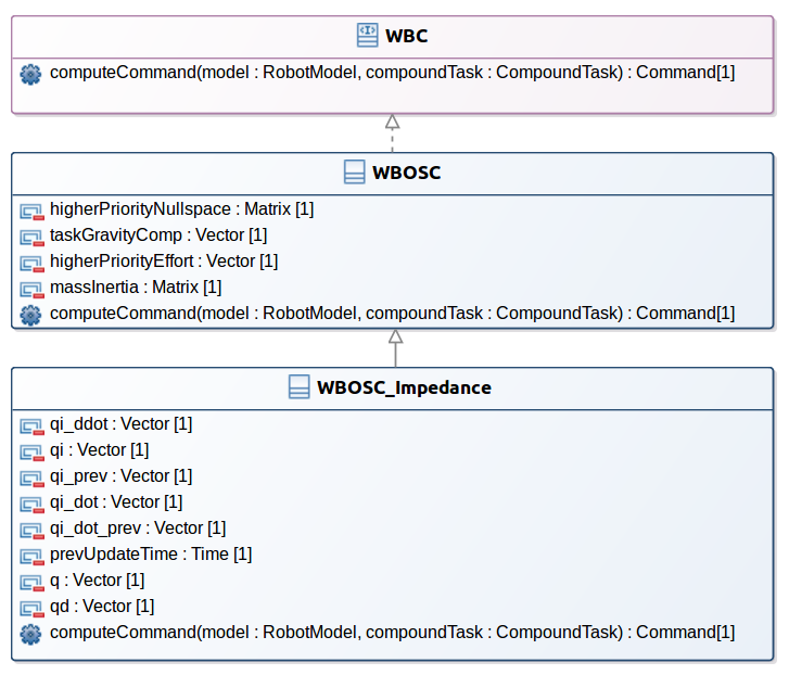
To support impedance-controlled robots, ControlIt! also comes with the WBOSC_Impedance plugin. Unlike effort-controlled robots, impedance-controlled robots take more than just effort commands. Specifically, in addition to effort, impedance controllers also take desired position and velocity commands, and optionally position controller gains when controller gain scheduling is desired. The benefit of using impedance control is the ability to attain higher levels of impedance. This is possible since the position and velocity control loop can be closed by the embedded joint controller, which typically has a higher servo frequency and lower communication latency than the WBC controller. The WBOSC_Impedance plugin extends the WBOSC plugin with an internal model that converts the effort commands generated by the WBOSC algorithm into expected joint positions and velocities. The member variables within the WBOSC_Impedance plugin that start with “qi_” hold the internal model’s joint states. The prevUpdateTime member variable records when this internal model was last updated. Each time computeCommand is called, WBOSC_Impedance computes the desired effort command using WBOSC. It then uses this effort command along with the robot model to determine the desired accelerations of each joint. WBOSC_Impedance then updates the internal model based on these acceleration values, the time since the last update, the previous state of the internal model, and the actual position and velocity of the joints. The derived joint positions, velocities, and efforts are saved within a Command object, which is returned. This control strategy was used on the upper body of NASA JSC’s Valkyrie robot to perform several DRC manipulation tasks as previously mentioned.
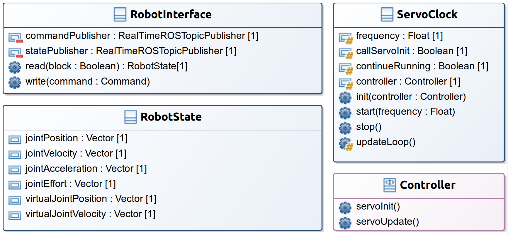
Hardware abstraction. To enable support for a wide variety of robot platforms, ControlIt! includes a hardware abstraction layer consisting of two abstract classes, the RobotInterface and the ServoClock, as shown in Figure 7. Concrete implementations are provided through dynamically loadable plugins. RobotInterface is responsible for obtaining the robot’s joint state and sending the command from the whole body controller to the robot. For diagnostic purposes, it also publishes the state and command information onto ROS topics using a real-time ROS topic publisher, which uses a thread-pool to offload the publishing process from the servo thread. ServoClock instantiates the servo thread and contains a reference to a Controller, which is implemented by the Coordinator. ServoClock is responsible for initializing the controller by calling servoInit() and then periodically executing the servo loop by calling the servoUpdate() method. Initialization using the actual servo thread is needed to handle situations where certain initialization tasks can only be done by the servo thread. This occurs, for example, when the servo thread is part of a real-time context meaning only it can initialize certain real-time resources.
ControlIt! includes libraries of RobotInterface and the ServoClock plugins as shown in Figure 8. RobotInterface plugins include general ones that communicate with a robot via three different transport layers: ROS topics (RobotInterfaceROSTopic), UDP datagrams (RobotIntefaceUDP), and shared memory (RobotInterfaceSM). These are meant for general use – ControlIt! includes generic Gazebo plugins and abstract classes that facilitate the creation of software adapters for allowing simulated and real robots to communicate with ControlIt! using these three transport layers. Among the three transport layers, shared memory has the lowest latency and is most reliable in terms of message loss. It uses the ROS shared memory interface package [110], which is based on boost’s interprocess communication library.
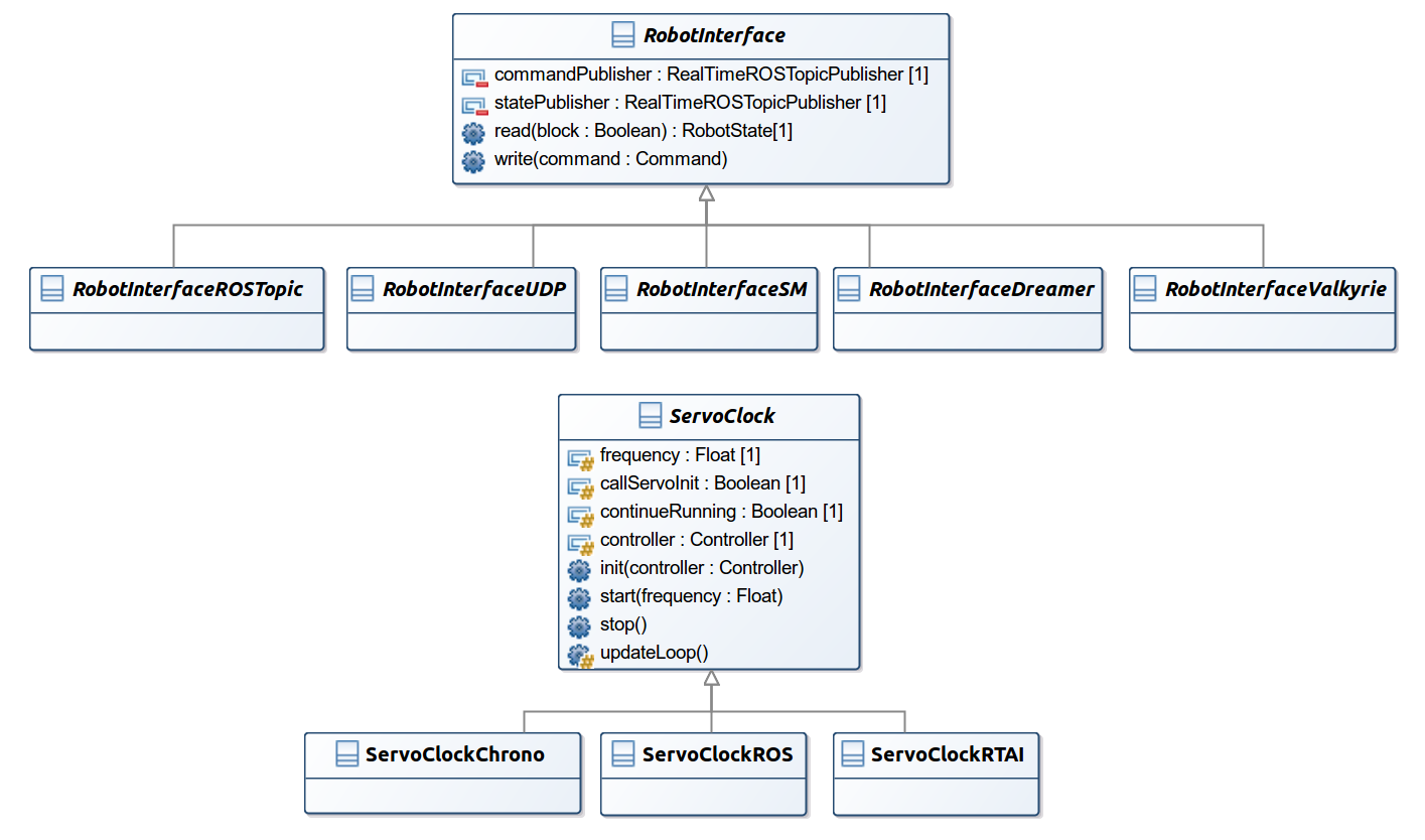
In addition to general RobotInterface plugins, ControlIt! also includes two robot-specific plugins, one for Dreamer (RobotInterfaceDreamer), and one for Valkyrie (RobotInterfaceValkyrie). RobotInterfaceDreamer interfaces with a RTAI real-time shared memory segment that is created by the robot’s software interface called the M3 Server. It also implements separate PID controllers for robot joints that are not controlled by WBC. They include the finger joints in the right hand, the left gripper joint, the neck joints, and the head joints. In the current implementation, these joints are fixed from WBC’s perspective. RobotInterfaceValkyrie interfaces with shared memory segment created by Valkyrie’s software interface. This involves integration with a controller manager provided by ros_control [6] to gain access to robot resources.
ControlIt! includes several ServoClock plugins to enable flexibility in the way the servo thread is instantiated and configured to be periodic. The current ServoClock plugin library includes plugins for supporting servo threads based on a ROS timer, a C++ std::chrono timer, or an RTAI timer. Support for additional methods can be included in the future as additional plugins.
4.2 Configuration and Integration
Support for configuration and integration is important because as a software framework ControlIt! is expected to be (1) used in many different applications and hardware platforms that require different whole body controllers and (2) just one component in a complex application consisting of many components. In addition, ControlIt!’s configuration and integration capabilities directly impacts the software’s usability, which must be high to achieve the goal of widespread use. ControlIt! supports integration through four mechanisms: (1) parameter reflection, which exposes controller parameters to other objects within ControlIt! and is used by the other two mechanisms, (2) parameter binding, which enables the parameters to be connected to external processes through an extensible set of transport layers, (3) events, which enable parameter changes to trigger the execution of external processes without the use of polling, and (4) services, which enable external processes to query information about the controller. ControlIt! supports configuration through scripts that enable users to specify the structure of the compound task and constraint set, the type of whole body controller and hardware interface to use, the initial values of the parameters, the parameter bindings, and the events. These scripts are interpreted during ControlIt!’s initialization to automatically instantiate the desired whole body controller and integrate it into the rest of the system. Details of ControlIt!’s support for configuration and integration are now discussed.
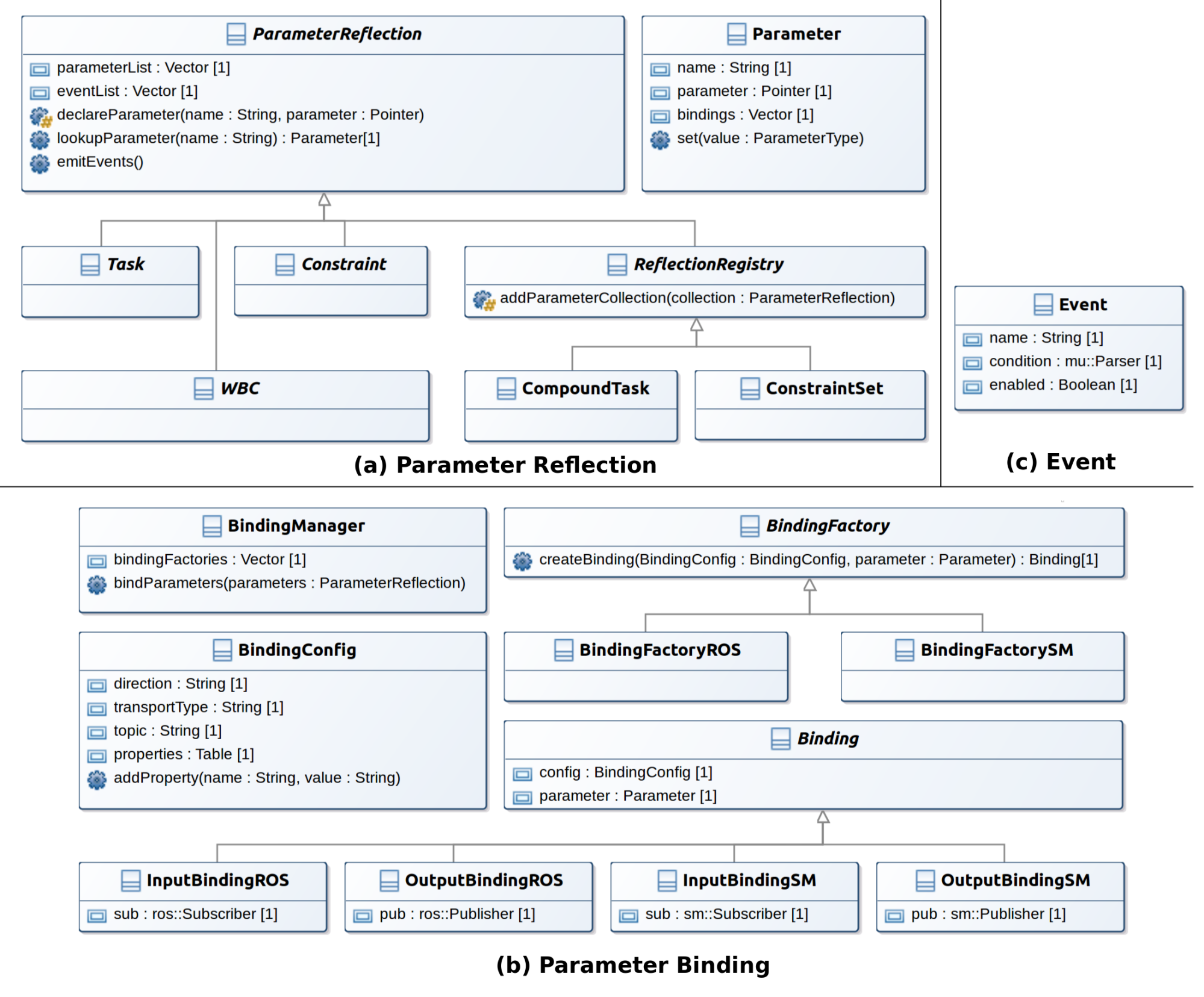
Parameter Reflection. Parameter reflection was originally introduced in Stanford-WBC. It defines a ParameterReflection parent class through which child class member variables can be exposed to other objects within ControlIt!. The API and class hierarchy of the ParameterReflection class is shown in Figure 9 (a). Parameter reflection enables internal control parameters to be exposed to other objects within ControlIt!. It consists of an abstract parent called ParameterReflection that provides methods for declaring and looking up parameters. When a parameter is declared, it is encapsulated within a Parameter object, which contains a name, pointer to the actual variable, a list of bindings, and a method to set the parameter’s value. Subclasses of ParameterReflection are able to declare their member variables as parameters and thus make them compatible with ControlIt’s parameter binding and event mechanism.
Parameter Binding. Parameter binding enables the integration of ControlIt! with other processes in the system by connecting parameters to an extensible set of transport layers. Its API and class hierarchy is shown in Figure 9 (b). The classes that constitute the parameter binding mechanism consist of a BindingManager that maintains a set of BindingFactory objects that actually create the bindings, and a BindingConfig object that specifies properties of a binding. The required properties include the binding direction (either input or output), the transport type, which is a string that must match the name of a Binding provided by a BindingFactory plugin, and a topic to which the parameter is bound. The BindingConfig also contains an extensible list of name- value properties that is transport protocol specific. For example, transport- specific parameters for ROS topic output bindings include the publish rate, the queue size, and whether the latest value published should be latched.
During the initialization process, BindingConfig objects are stored as parameters within a ParameterReflection object, which is passed to the BindingManager. The BindingManager searches through its BindingFactory objects, which are dynamically loaded via plugins, for factories that are able to create the desired binding. The current bindings in ControlIt’s binding library include input and output bindings for ROS topics and shared memory topics. More can be easily added in the future via the plugin architecture. The newly created Binding objects are stored in the parameter’s Parameter object. When a parameter’s value is set via Parameter.set(), the new value is transmitted through output bindings to which the parameter is bound. This enables changes in ControlIt! parameters to be published onto various transport layers and topics notifying external processes of the latest values of the parameters. Similarly, when an external process publishes a value onto a transport layer and topic to which a parameter is bound via an input binding, the parameter’s value is updated to be the published value. This enables, for example, external processes to dynamically change a task’s references or controller gains, which is necessary for integration.
Events. Events contain a logical expression over parameters that are interpreted via muParser [111], an open-source math parser library. Its API is shown in Figure 9 (c). Events are stored in the ParameterReflection parent class. The servo thread calls ParameterReflection.emitEvents() at the end of every servo cycle. The names of events whose condition expression evaluates to true are published on ROS topic /[controller name]/events. Events contain a boolean variable called “enabled” that is used to prevent an event from continuously firing when the condition expression remains true since this would likely flood the events ROS topic. Instead, events maintain a fire-once semantic meaning they only fire when the condition expression changes from false to true.
Service-based controller introspection capabilities. To further assist ControlIt! integration, into a larger system, ControlIt! also includes a set of service-based introspection capabilities. Unlike ROS topics, which are asynchronous unidirectional, ROS services are bi-directional and synchronous. ControlIt! uses this capability to enable external processes to query certain controller properties as it is running. For example, two often- used services include /[controller name]/diagnostics/getTaskParameters, which returns a list of all tasks in the compound task, the parameters, and their parameter values, and /[controller name]/diagnostics/getRealJointIndices, which returns the ordering of all real joints in the robot. This is useful to determine the joint order when updating the reference positions of a posture task or interpreting the meaning of the posture task’s error vector. A full list of ControlIt’s service-based controller introspection capabilities is provided in C.
Script-based configuration and initialization. As previously mentioned, ControlIt! supports script-based configuration specification and initialization enabling integration into different applications and platforms without being recompiled. This is necessary given the plethora of properties that must be defined and the wide range of anticipated applications and hardware platforms. To instantiate a whole body controller using ControlIt!, the user must specify many things including the compound task, constraint set, whole body controller, robot interface, servo clock, initial parameter values, parameter bindings, and events. In addition, there are numerous controller parameters as defined in Appendix B. ControlIt! enables users to define the primary WBC configuration and integration abstractions including tasks, constraints, compound tasks, constraint set, parameter bindings, and events via a YAML file whose syntax is given in Appendix D. The remaining parameters are defined through the ROS parameter server, which can also be initialized via another YAML file that is loaded via a ROS launch file [112]. ROS launch is actually a powerful tool for loading parameters and instantiating processes. ControlIt! leverages this capability to enable users to initialize and execute a ControlIt! whole body controller using a single command.
4.3 Multi-threaded Architecture
Higher servo frequencies can be achieved by decreasing the amount of computation in the servo loop. The amount of computation can be reduced because robots typically move very little during one servo period, which is usually 1ms. Thus, state that depends on the robot configuration like the robot model and task Jacobians often do not need to be updated every servo cycle. ControlIt! takes advantage of this possibility by offloading the updating of the robot model and the task states, which include the task Jacobians, into child threads. Specifically, ControlIt! uses three threads as shown in Figure 10. They include (1) a Servo thread that executes the actual servo loop, (2) a ModelUpdater thread that is responsible for updating the robot model, which includes the kinematics, inertia matrix, gravity compensation vector, the constraint set, and the virtual linkage model, and (3) a TaskUpdater thread that is responsible for updating the states of each task in the compound task, which includes the task Jacobians. The Servo thread is instantiated by the ServoClock and can thus be real-time when, for example, ServoClockRTAI is used. ModelUpdater and TaskUpdater are child threads that do not operate in a real-time manner. From a high-level perspective, Servo provides ModelUpdater with the latest joint states. The ModelUpdater uses this information to update the robot model in parallel with the Servo thread, and provides the updated robot model to the Servo when complete. Whenever the robot model is updated, the Servo thread provides the updated model to the TaskUpdater thread, which updates the task states. These updated task states are then provided to the Servo thread. Details on how this process is achieved in a manner that is non-blocking and safe are now discussed.
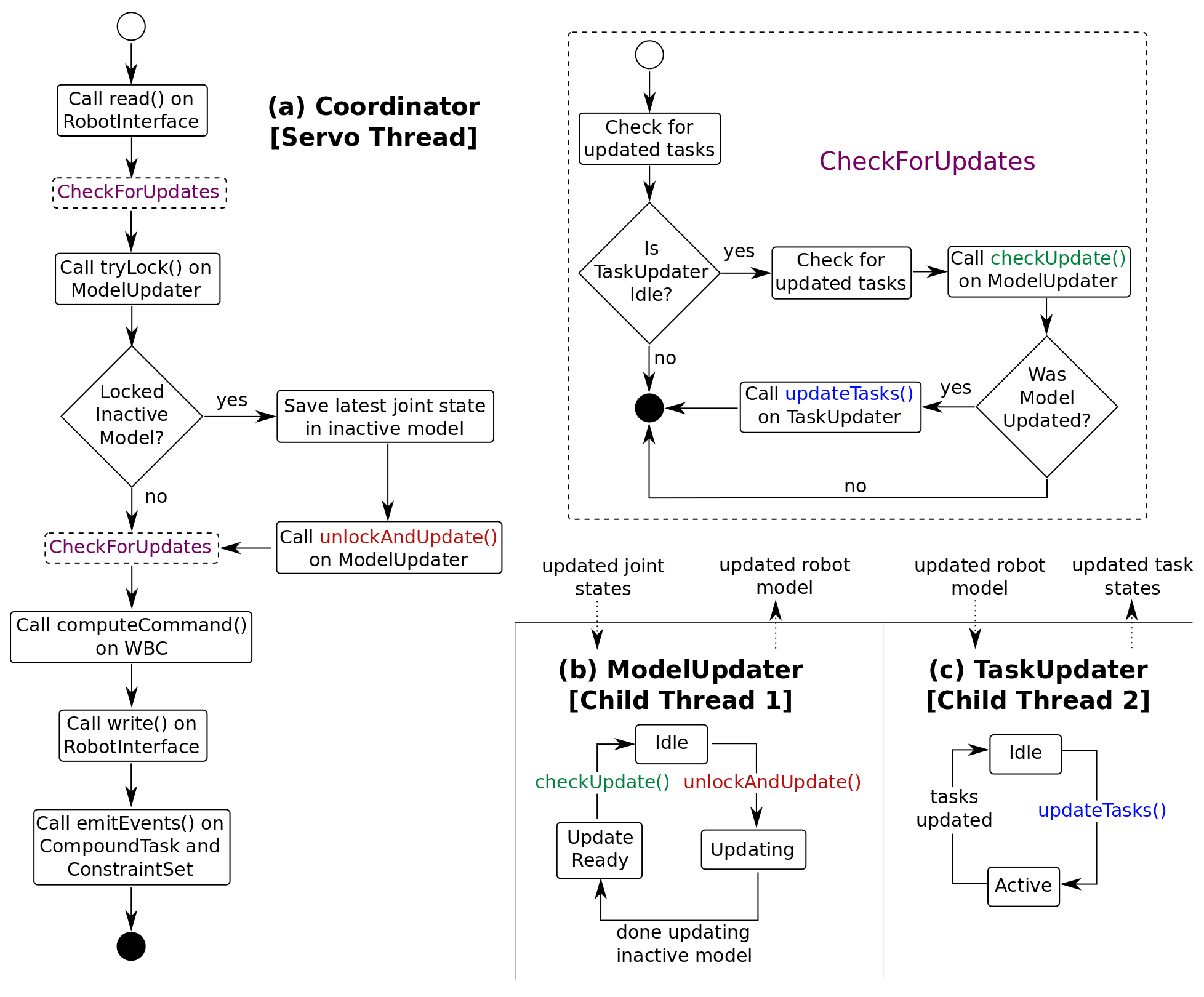
Two key requirements of the multi-threaded architecture are (1) the Servo thread must not block and (2) there must not be any race conditions between threads. The first requirement implies that the servo thread cannot call the blocking lock() method on the mutexes protecting the shared states between it and the child threads. Instead, it can only call the non-blocking try_lock() method, which returns immediately if the lock is not obtainable. ControlIt!’s multi-threaded architecture is thus structured to only require calls to try_lock() within the Servo thread. To prevent race conditions between threads, two copies of the robot model and task state are maintained: an “active” copy that is used by the Servo thread, and an “inactive” one that is updated by the non-servo threads. Updates from the child threads are provided to the Servo thread by swapping the active and inactive states. This swapping is done by the Servo thread in a non-blocking and opportunistic manner.
Figures 10 (a) and (b) show how the Servo thread passes the latest joint state information to the ModelUpdater thread and trigger it to execute. After obtaining the latest joint states by calling RobotInterface.read() and checking for updates from the child threads by executing the CheckForUpdates FSM, the Servo thread attempts to obtain the lock on the mutex protecting the inactive robot model by calling ModelUpdater.tryLock(). If it is able to obtain the lock on the mutex, it saves the latest joint states in the inactive robot model and then triggers the ModelUpdater thread to execute by calling ModelUpdater.unlockAndUpdate(). As the name of this method implies, the Servo thread also releases the lock on the inactive model thereby allowing the ModelUpdater thread to access and update the inactive robot model. If the Servo thread fails to obtain the lock on the inactive model, the ModelUpdater thread must be busy updating the inactive model. In this situation, the Servo thread continues without updating the inactive model.
To prevent race conditions between the Servo thread and the child thread, updates from child threads are opportunistically pulled by the Servo thread. This is because the child threads operate on inactive versions of the robot model and task states, and only the Servo thread can swap the active and inactive versions. There are two points in the servo loop where the Servo thread obtains updates from the child threads. This is shown by the two “CheckForUpdates” states in left side of Figure 10 (a). They occur immediately after obtaining the latest joint states by calling RobotInterface.read(), and immediately after triggering the ModelUpdater thread to run or failing to obtain the lock on the inactive robot model. More checks for updates could be interspersed throughout the servo loop but we found these two placements to be sufficient.
The operations of the CheckForUpdates state are shown in the upper-right corner Figure 10. The Servo thread first obtains task state updates and then checks whether the TaskUpdater thread is idle. If it is idle, the Servo thread again checks for updated task states. This is to account for the following degenerate thread interleaving during the previous check for updated task states that would result in the permanent loss of updated task state:
-
1.
The Servo thread begins to check some of the tasks for updated states.
-
2.
TaskUpdater thread updates all of the tasks including those that were just checked by the Servo thread and returns to idle state. Note that this is possible even if the Servo thread is real-time and has higher priority since the TaskUpdater may be executing on a different CPU core.
-
3.
The Servo thread completes checking the remainder of the tasks for updates.
In the above scenario, the tasks that were checked in step 1 would have updated states that would be lost without the Servo-thread re-checking for them after it confirms that the TaskUpdater is idle. In a worst-case scenario, the TaskUpdater thread may update all of the tasks after the Servo thread checks for updates but before it checks whether the TaskUpdater is idle, resulting in the loss of updated state from every task. The loss of updated task state is not acceptable despite the presence of future update rounds since it is theoretically possible for the updated states of the same tasks to be continuously lost during every update round. While seemingly improbable, this “task update starvation” problem was actually observed and thus discovered while testing ControlIt! on Valkyrie.
After verifying that the TaskUpdater thread is idle and ensuring all of the updated task states were obtained, the Servo thread next checks for an updated robot model by calling ModelUpdater.checkUpdate(). This method switches to the updated robot model if one is available. If the model was updated, the Servo thread then calls TaskUpdater.updateTasks() passing it the updated robot model. This method is non-blocking since the TaskUpdater must be idle. It triggers the TaskUpdater to update the states of each task in the compound task. Note that if the robot model was not updated, the Servo thread does not call TaskUpdater.updateTasks() since task state updates are based on changes in the robot model.
The current implementation does not consider the possibility that the active robot model or task states become excessively stale. This can occur if the robot moves so quickly that the model changes significantly since the last time it was updated. ControlIt’s multi-threaded architecture can be easily modified to monitor difference between the current robot state and the robot state that was used to update the currently-active robot model and task states. If the difference exceeds a certain threshold, the Servo loop can update the active model itself to prevent excessive staleness. We currently do not implement this because our evaluations did not indicate the need for it.
Sometimes a multi-threaded architecture is not necessary when the robot has a limited number of joints, the control computer is particularly fast, and the compound task is structured to reduce computational complexity (e.g., by using simpler tasks or limiting the number of tasks that share the same priority level). In this case, ControlIt!’s multi-threaded architecture can be disabled by setting two ROS parameters, single_threaded_model and single_threaded_tasks, to be true prior to starting ControlIt!. Details of these parameters are given in Table 7, which is in B. When these parameters are set to true, the servo loop updates the model and task states each cycle of the servo loop.
Regardless of whether a multi-threaded architecture is used, the servo loop must be executed in a real-time manner. To help facilitate this, no dynamic memory allocation can occur once the servo loop starts. The initialization process consists of instantiating all objects using their constructors and then calling init() methods on all of the objects. All necessary memory is allocated during either the construction or initialization phases. To ensure no memory is being dynamically allocated in the linear algebra operations that are extensively used in WBOSC, we tested the code by defining the EIGEN_RUNTIME_NO_MALLOC preprocessor macro prior to including the Eigen headers.
5 Evaluation
We integrate ControlIt! with Dreamer, a dual-arm humanoid upperbody made by Meka Robotics, which was purchased by Google in December 2013. Dreamer’s arms and torso contains series elastic actuators and high fidelity torque control. The robot is modeled as a (16 + 6 = 22) DOF robot where 16 are the physical joints and the remaining 6 DOFs represent the floating DOFs.555WBOSC by default always assumes a floating base. In the case when the robot is fixed in place, it is represented in WBOSC as a constraint. This enables ControlIt! to be more generic in terms of supporting both mobile and fixed robots.
5.1 Product Disassembly Application
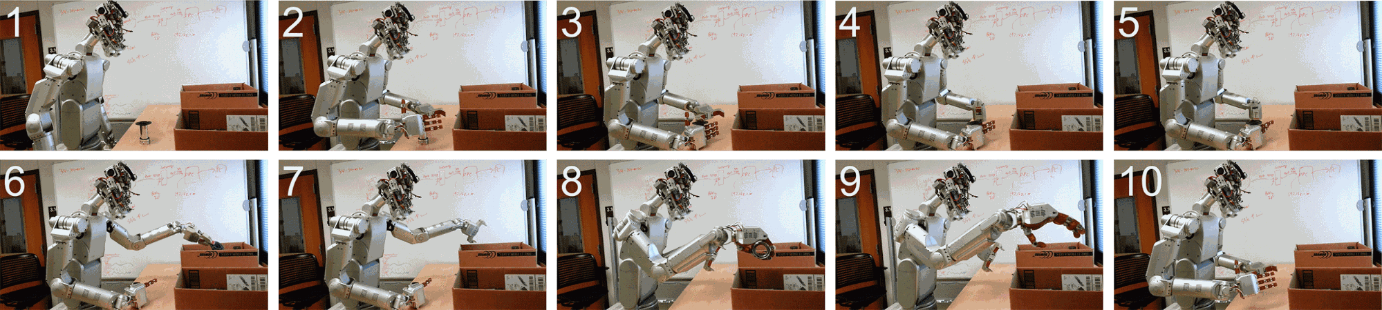
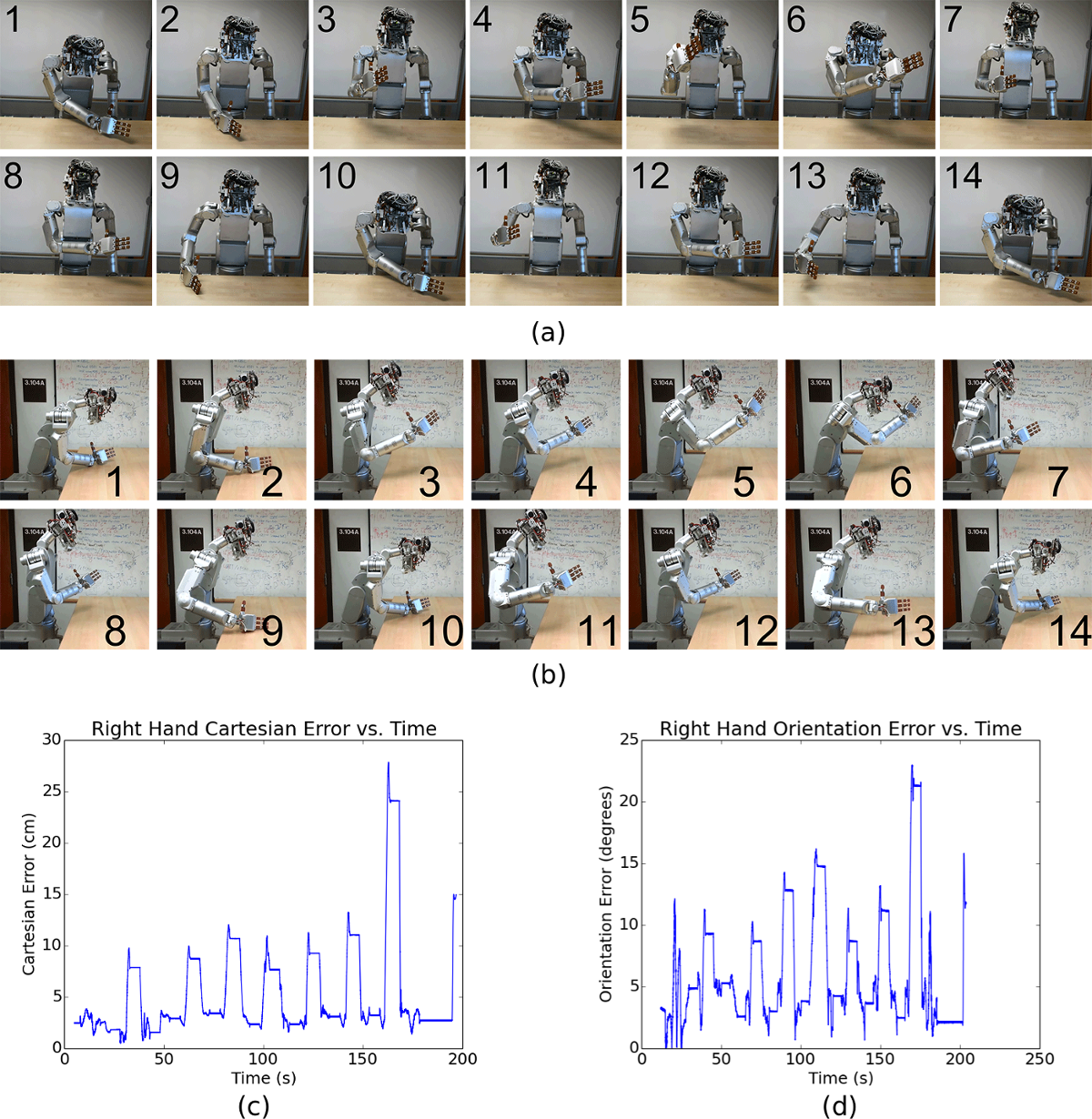
Using ControlIt!, we developed an application that makes Dreamer disassemble a product. A sequence of snapshots showing Dreamer performing the task using ControlIt! is given in Figure 11. The task is to take apart an assembly consisting of a metal pipe with a rubber valve installed at one end. To remove the valve, Dreamer is programed to grab and hold the metal pipe with her right hand while using her left gripper to detach the valve. Once separated, Dreamer places the two pieces into separate storage containers.
Two compound task configurations were used to achieve the product disassembly task:
-
1.
single priority level containing a joint position task
-
2.
dual priority level containing two higher priority Cartesian position tasks and two 2D orientation tasks (one for each wrist) and a lower priority posture task.
The benefits of the second configuration are shown by demonstrating how changing just three controller parameters, i.e., the Cartesian position of the product, enables the controller to adapt to changes in the product’s location while continuously minimizing the squared error of the posture task. This is in the spirit of WBC where changes in a low-dimensional space (three Cartesian dimensions) results in desirable changes in a larger dimensional space (e.g., the number of DOFs in the robot).
Developing the product disassembly application required writing new RobotInterface and ServoClock plugins that enable ControlIt! to work with Dreamer. This is because Dreamer comes with the M3 software that is designed specifically for robots built by Meka. The M3 software includes the M3 Server, which instantiates an RTAI shared memory region through which ControlIt! can transmit torque commands and receive joint state information. In addition, the M3 Server also implements the transmissions that translate between joint space and actuator space and the protocol for setting the modes and gains of the joint controllers executing on the robot’s DSPs. Other useful tools provided by the M3 software include applications for tuning and calibrating individual joints. The ControlIt! robot interface we developed for Dreamer is called RobotInterfaceDreamer. It uses the shared memory region created by the M3 Server to connect the WBOSC controller to the robot, and implements separate simpler controllers for the joints that are not controlled by WBOSC. These joints include the finger joints in the right hand, the left gripper joint, the neck joints, and the head joints (eyes and ears). In the current implementation, these joints are fixed in place from WBOSC’s perspective. While this is not true, they are located at the robot’s extremities and are attached to relatively small masses; the feedback portion of the WBOSC controller is able to sufficiently account for these inaccuracies as demonstrated by the successful execution of the application.
Because Dreamer’s M3 software is designed to work with RTAI we created an RTAI-enabled servo clock called ServoClockRTAI, which instantiates a RTAI real-time thread for executing the servo loop within ControlIt!. Whereas RobotInterfaceDreamer is specific to Dreamer, ServoClockRTAI can be re-used on any robot that is RTAI-compatible to get real-time execution semantics.
| Property | Control PC | Application PC |
|---|---|---|
| CPU | Intel Core i7-4771 @ 3.56GHz | Intel Core i7-4771 @ 3.56GHz |
| Motherboard | Zotac H87 | JetWay JNF9J-Q87 |
| OS | Ubuntu 12.04 server, 32-bit, kernel 2.6.32.20, RTAI 3.9, EtherCAT 1.5.1 | Ubuntu 14.04 desktop, 64-bit, Kernel 3.13.0-44 |
| Middleware and Applications | ROS Hydro, ControlIt!, M3 Server | ROS Indigo, demo applications, Gazebo |
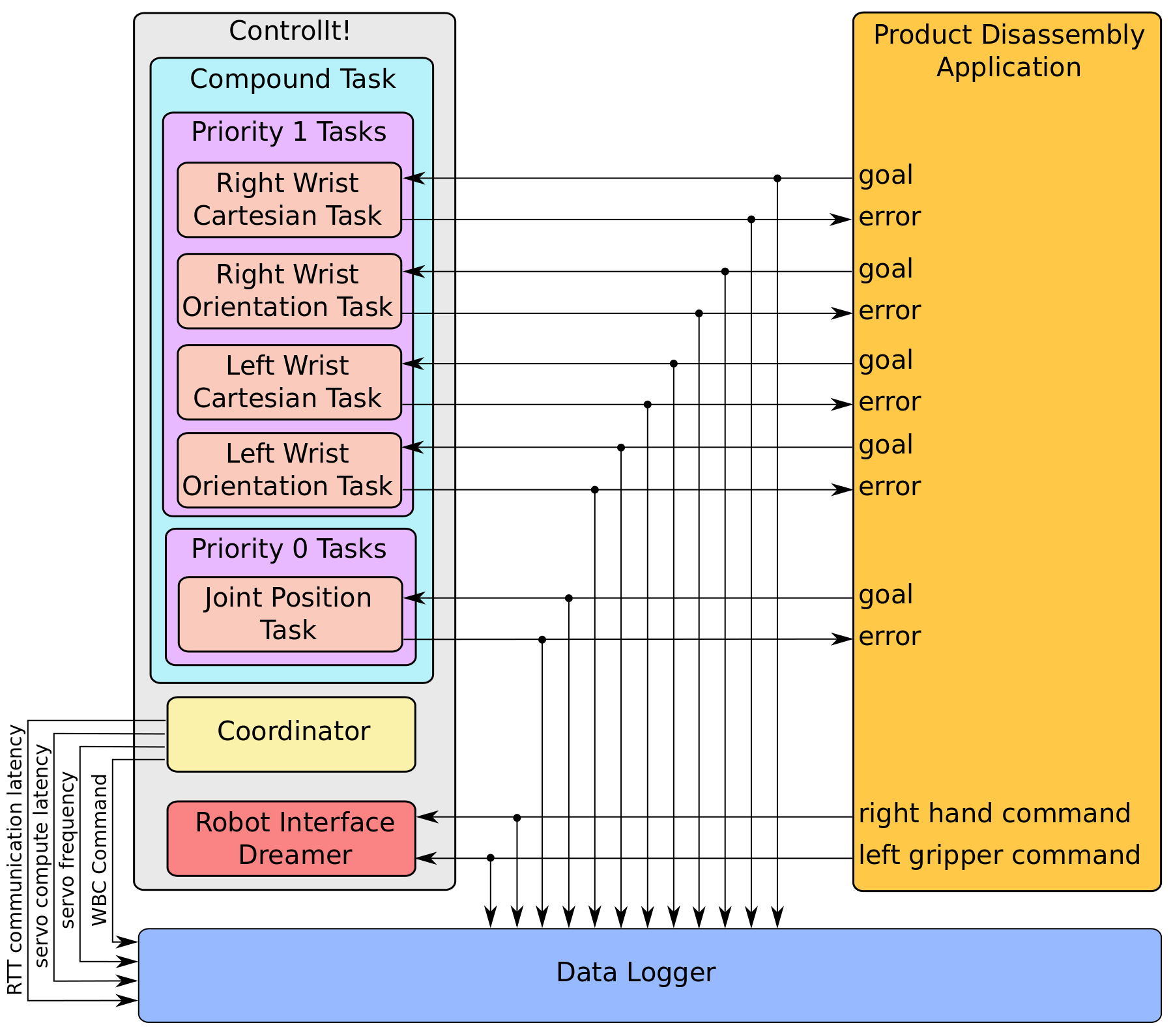
Since Dreamer contains a 2-DOF torso and two 7-DOF arms, we use a compound task containing a Cartesian position and orientation task for each of the two end effectors, and a lower priority joint position task for defining the desired posture. The constraint set contains two constraints: a FlatContactConstraint for fixing the robot’s base to the world and a CoactuationConstraint for the upper torso pitch joint that is mechanically connected to the lower torso pitch joint by a 1:1 transmission. This results in the positions and velocities of the two joints to always be the same. The Jacobian of the CoactuationConstraint consists of one row and a column for each DOF in the robot’s model. The column representing the slave joint contains a 1 and the column representing the master joint contains the negative of the transmission ratio. Details of these types of constraints were discussed in [27].
Finally, the goal state and error of every task in the compound task are bound to ROS topics so they can be accessed by the application. A data logger based on ROSBag [113] is used to record experimental data. Figure 12 shows how the various components are connected. Kinesthetic teaching is used to obtain the trajectories for performing the task, which consists of manually moving the robot along the desired trajectories while taking snapshots of the robot’s configuration. Cubic spline is used to interpolate intermediate points between snapshots. Note that the application is open-loop in that the robot does not sense where the metal pipe and valve assembly is located. We manually reposition the metal pipe and valve assembly at approximately the same location prior to executing the application.
Before the application can be successfully executed, calibration and gain tuning must be done for every joint and controller in the system. We calibrated and tuned one joint at a time starting from those in the robot’s extremities (e.g., wrist yaw joints) and moving inward to joints with increasing numbers of child joints. Once all of the joints were calibrated and torque controller gains tuned, we proceeded to tune the task-level gains in the following order: joint position task, Cartesian position tasks, and finally orientation tasks. The gains used are given in E. Note that these gains are dependent on ControlIt’s servo frequency, which we set to be 1kHz, and the end-to-end communication latency between the whole body controller and the joint torque controllers, which is about 7ms.
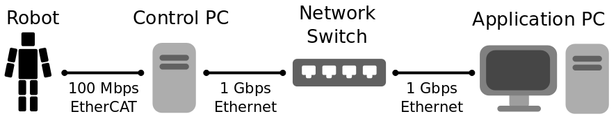
The system architecture is shown in Figure 13. It consists of the robot, the control PC, and the application PC. The robot communicates with the control PC over a 100Mbps EtherCAT link. The control PC communicates with an application PC via a 2-hop 1Gbps Ethernet network. The control PC runs ControlIt! on an older but real-time patched version of Linux relative to the application PC. This is because upgrading the operating system on the control PC while maintaining compatibility with RTAI and necessary drivers like EtherCAT and ensuring acceptable real-time performance is a difficult and time consuming process that requires extensive testing. The product disassembly application could run directly on the Control PC, but we chose to run in on a different application PC to emphasize the ability to integrate ControlIt! with remote processes and to allow the application to make use of a newer operating system, middleware, and libraries. In addition, running the application on a separate PC reduces the likelihood that the application would interfere with the whole body controller especially if the application includes a complex GPU-accelerated GUI.
The application PC includes the dynamics simulator Gazebo [114]. When developing the product disassembly application, we always tested the application in simulation prior to on real- hardware, reducing the number of potentially-catastrophic problems encountered on hardware. For example, on the real hardware, if the application crashes while the arms are above the table, the arms may slam into the table with enough force to result in damage to the robot and perhaps the table. Testing the application in simulation enabled us to evaluate application stability. We implemented the application in Python (see F for an example code fragment), which further increases the importance of simulation testing since there’s no compilation stage to identify potential problems. Note that the application could have been written in any programming language supported by ROS [115]. Because ControlIt! has a hardware abstraction layer consisting of a RobotInterface plugin and a ServoClock plugin, switching between testing the application in simulation versus on the real hardware is simple and does not require any changes to the code.
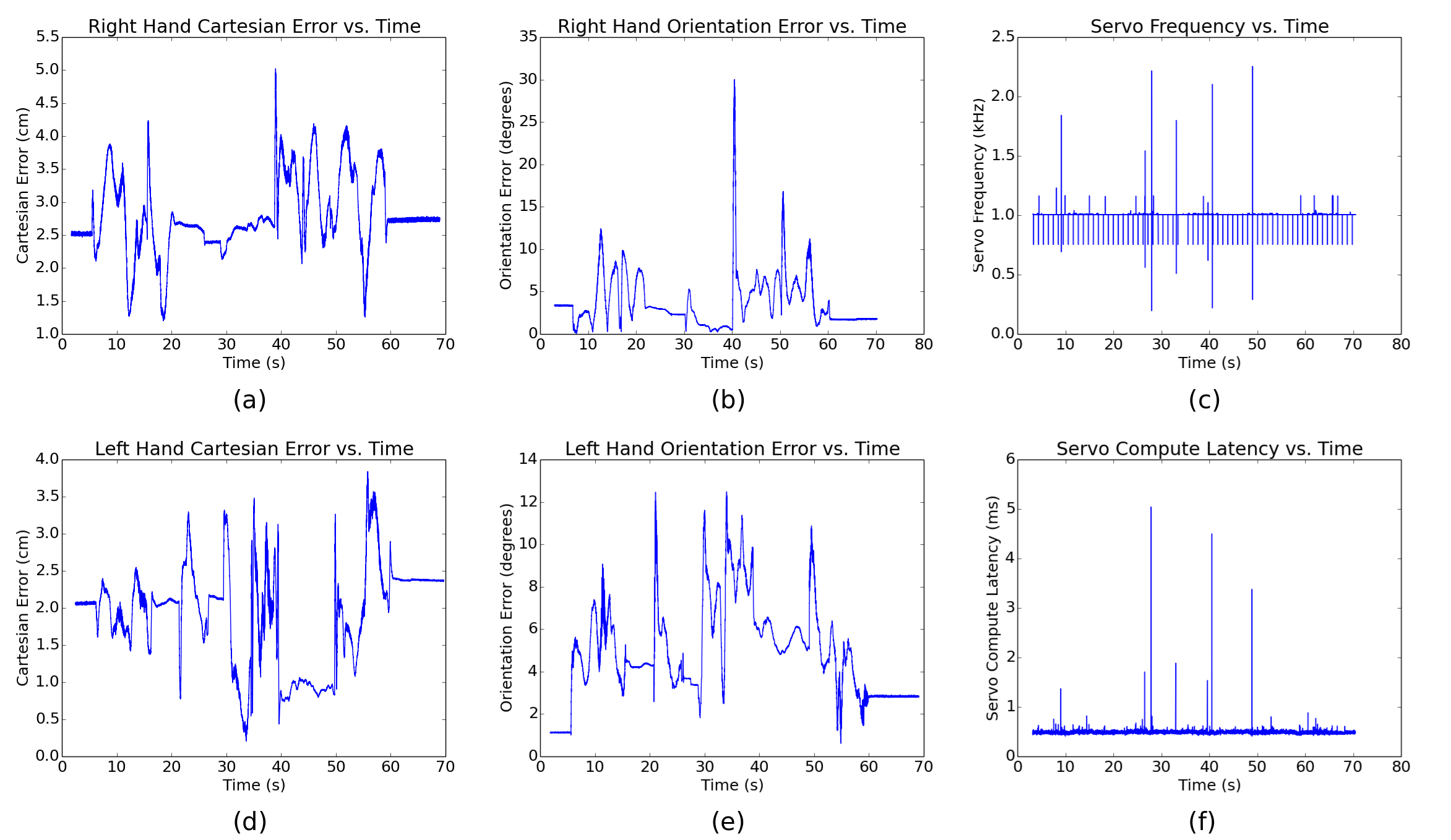
After tuning the controllers, we were able to repeatedly execute the application in a reliable manner. Figure 14 shows performance data collected from one of the many executions of the application. The data was collected from ROS topics to which internal controller parameters were bound. Average statistics are given in Table 2. The results show average servo computational latencies of about 0.5ms, which is the amount of time the servo thread takes to compute one cycle of the servo loop and is an order of magnitude faster than the 5ms achieved by UTA-WBC. Table 3 shows the results of an experiment that obtains a detailed breakdown of the latencies within the servo loop by instrumenting the servo loop with timers. The values are the average over 1000 executions of the servo loop. The vast majority of the servo loop’s computational latency is from executing the WBOSC algorithm to get the next command. Multi-threading significantly decreases the latency of updating the model and slightly decreases the latency of computing the command. The slightly higher average total latency in the multi-threaded case in Table 3 relative to the servo computational latency in Table 2 is most likely due to the additional instrumentation that was addded to the servo loop to obtain the detailed latency breakdown information.
| Statistic | Sample Size | Average | Units |
|---|---|---|---|
| Right Hand Cartesian Error | 49,137 | 2.79 0.56 | cm |
| Right Hand Orientation Error | 55,735 | 3.72 3.12 | degrees |
| Left Hand Cartesian Error | 43,026 | 1.91 0.67 | cm |
| Left Hand Orientation Error | 50,381 | 4.86 2.23 | degrees |
| Servo Frequency | 67,225 | 1005.43 15.68 | Hz |
| Servo Compute Latency | 64,118 | 0.487 0.0335 | ms |
The results in Table 2 also show Cartesian positioning errors of up to 5cm and orientation errors of up to 30 degrees, though the errors are much less on average. Note that the Cartesian position and orientation errors are both model-based meaning they are derived from the joint states and the robot model and not from external sensors like a motion capture system. Thus, the accuracy of these error values depend on the accuracy of the robot’s model and should not be considered absolute. However, they do represent the errors that the whole body controller sees and attempts to eliminate but cannot because the feedback gains cannot be made sufficiently high to remove the errors.
| Step in Servo Loop | Multi-Threaded Latency | Single-Threaded Latency |
|---|---|---|
| Read Joint State | 0.020 0.0020 | 0.020 0.0026 |
| Publish Odometry | 0.014 0.0041 | 0.0147 0.00526 |
| Update Model | 0.0075 0.00256 | 0.272 0.00235 |
| Compute Command | 0.470 0.0128 | 0.497 0.0120 |
| Emit Events | 0.0036 0.00028 | 0.0041 0.00027 |
| Write | 0.0116 0.00075 | 0.0125 0.00119 |
| Total | 0.528 0.0144 | 0.820 0.0145 |
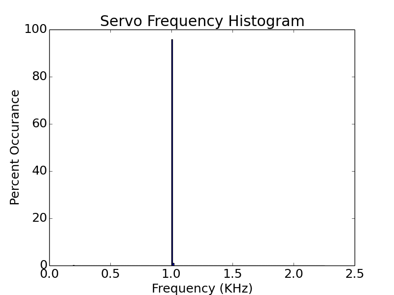
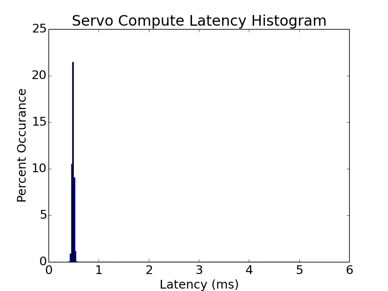
Figures 14(c) and 14(f) indicate a problem with achieving real-time semantics on the control PC since the servo frequency and computational latency occasionally suffers excessively low and high spikes. The lowest servo frequency measured in this sample execution is only 195.3Hz, the maximum is 2.254kHz, and the average is 1.01 0.016kHz. Coincident with the large spikes in the servo frequency are large spikes in the servo compute latency. This indicates that something in the operating system or underlying hardware occasionally prevented ControlIt!’s real-time servo thread from executing as expected. Despite the violations in real-time semantics and errors in Cartesian position and orientation, the ControlIt! is still able to make Dreamer reliably perform the task. This is probably because the spikes are rare as shown by the histograms of the same data as shown in Figure 15.
5.2 Latency Benchmarks
The results in Table 2 indicate that the servo loop spends about 0.487 0.0335 ms computing the next command. This is for a specific compound task with two priority levels and 2D orientation tasks and with multi-threading enabled. We now vary the compound task configuration in terms of both number of priority levels (which affects the number of tasks per priority level) and types of orientation task used. We also evaluate both multi-threaded and single-threaded execution of ControlIt!.
All tests involve five tasks: a Cartesian position task for each of the two end effectors, an orientation task for each of the two end effectors, and a posture task. Two types of orientation tasks are used: 2D and 3D. When 2D orientation tasks are used, only 5 DOFs of each end effector are controlled by the orientation and position tasks; the sixth DOF is controlled by a lower priority posture task. When 3D orientation tasks are used, all 6 DOFs of each end effector are controlled by the orientation and position tasks.
Three configurations of the compound task are evaluated. The first configuration uses two priority levels and assigns all four Cartesian position and orientation tasks to be at the higher priority level. The posture task is located at the lower priority level. The second configuration uses three priority levels and assigns the Cartesian position tasks to be at the highest priority level and the orientation tasks to be in the middle priority level. This is possible since the orientation tasks operate within the nullspace of the Cartesian position tasks. Like the first configuration, the posture task is located at the lowest priority level. The third configuration uses 5 priority levels. The two Cartesian position tasks are placed in the top two priority levels. The two orientation tasks are placed in the next two priority levels. Finally, the posture task is located in the lowest priority level.
| Priority Levels / Task Allocation | Orientation Task | Threading | Latency (ms) |
|---|---|---|---|
| 2 priority levels | 2D | multi | 0.528 0.0144 |
| 4 tasks at higher priority | single | 0.820 0.0145 | |
| 1 task at lower priority | 3D | multi | 0.999 0.0261 |
| single | 1.289 0.0218 | ||
| 3 priority levels | 2D | multi | 0.494 0.0161 |
| 2 tasks at highest priority | single | 0.764 0.0217 | |
| 2 tasks at middle priority | 3D | multi | 0.788 0.0212 |
| 1 task at lowest priority | single | 1.068 0.0207 | |
| 5 priority levels | 2D | multi | 0.477 0.0155 |
| 1 task at each level | single | 0.744 0.0386 | |
| 3D | multi | 0.603 0.0166 | |
| single | 0.882 0.0168 |
The results are shown in Table 4. The use of multi-threading significantly decreases computational latency by about 0.2-0.3 ms. Interestingly, distributing the tasks across more priority levels decreases computational latency. In this case, placing the orientation tasks and Cartesian position tasks at different priority levels results in a significant decrease in servo computational latency. This is because the Jacobians and commands of all tasks within the same priority level are concatenated into a large matrix and, in this case, performing operations on large matrices takes more time than performing multiple operations and nullspace projections using smaller matrices.
Note that ControlIt! can maintain a 1kHz servo frequency in many of the compound task configurations even when running in single-threaded mode. Specifically, when 2D orientation tasks are used, 1kHz servo frequencies are achieved in all compound task configurations. When 3D orientation tasks are used, 1kHz servo frequencies can be achieved when the five tasks are spread across five priority levels. The ms that’s achieved in this case is similar to the ms that’s achieved using an optimized quadratic programming WBC algorithm [61].
5.3 Flexible End Effector Repositioning
As previously mentioned, the product disassembly application operates open- loop and requires the product to be placed at approximately the same location at the beginning of each execution of the application. For the application to be more robust, additional sensors need to be integrated that can determine the actual location of the product and communicate this information to the application. Such a sensor could be easily integrated since the application is a ROS node meaning it can simply subscribe to the ROS topic onto which the sensor publishes the actual location of the product. Once the application knows where the product is located, it can generate the Cartesian space trajectories to allow the end effectors to disassemble the product.
To demonstrate the ability for ControlIt! to make Dreamer follow different Cartesian space trajectories based on a sensed Cartesian goal coordinate, we created an application that makes Dreamer’s right hand move to random Cartesian positions while keeping the lower priority joint position task unchanged. The results are shown in Figure 16. Note that the right hand is able to move into a wide range of Cartesian positions and that the whole body of the robot moves to help achieve the goal of the right hand’s Cartesian position task. The elevated error values that periodically appear in Figures FlexibleCartesianPositioning (c) and (d) are due to the goal Cartesian position being moved beyond the robot’s workspace. Note that despite this problem the controller remains stable. This demonstrates ControlIt’s ability to be integrated into different applications and WBOSC’s ability to handle robot redundancies in a predictable and reliable manner.
6 Discussion
In this section, we provide a brief history of ControlIt’s development followed by future research directions.
6.1 History of ControlIt!’s Development
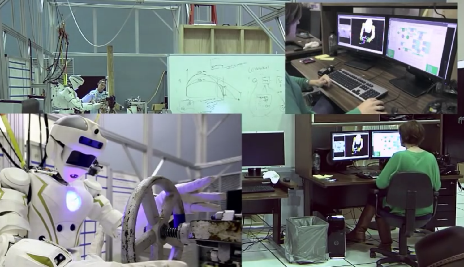
Prior to integration with Dreamer, ControlIt! was initially developed for NASA JSC’s Valkyrie humanoid robot (now called R5) [116]. Software and hardware development commenced simultaneously in October 2012. Since hardware development took nearly a year, the first year of developing and testing ControlIt! involved using a simulated version of Valkyrie in Gazebo [114]. During this phase, ControlIt! was initially used to control individual parts of the robot, e.g., each individual limb, the lower body, the upper body, and finally the whole robot. By the summer of 2013, ControlIt! was used to control 32-DOFs of Valkyrie in simulation (6 DOFs per leg, 7 DOFs per arm, 3 DOFs in the waist, and 3 DOFs in the neck). Compound tasks consisting of up to 15 tasks were employed. They include Cartesian position and orientation tasks for the wrists, feet, and the head, an orientation task for the chest, a center of mass task and posture task for the whole robot, and center of pressure tasks for the feet. Contact constraints for the hands and feet were configured, though not always enabled, depending on whether contact with the environment was being made. Management of all of these tasks and constraints were done using a higher-level application called Robot Task Commander (RTC) [99], which provided a graphical user interface for operators to instantiate and configure controllers based on ControlIt!, integrate these controllers with planners and other processes via ROS topics (locomotion was done using a phase space planner [117]), and sequence their execution within a finite state machine. Integration of ControlIt! with Valkyrie in simulation was successful. We were able to do most of the DRC tasks including valve turning, door opening, power tool manipulation, ladder and stair climbing, water hose manipulation, and vehicle ingress. This enabled us to pass the DRC critical design review in June 2013 and continue to participate in the DRC Trials as a Track A team.
By the end of Summer 2013, Valkyrie’s hardware development was nearing completion. At this point we began integrating ControlIt! with actual Valkyrie hardware. After using ControlIt! to control parts of the robots individually, we attempted to control all 32 DOFs but ran into problems where gains could not be increased high enough to sufficiently reduce errors due to modeling inaccuracies. The robot could stand under joint position control but it was not sufficiently stiff to locomote and certain joints like the knees and ankles would frequently overheat. We later hypothesized that one problem was likely due to the communication latencies between ControlIt! and the joint-level controllers being too high. We have since developed a strategy called embedded damping to help maintain stability despite the high communication latency [118]. Since we could not control all 32 DOFs in time for the DRC Trials in December 2013, we resorted to use ControlIt! on Valkyrie’s upper body to perform several DARPA Robotics Challenge tasks including opening a door, using a power tool, manipulating a hose, and turning a valve. Laboratory tests of ControlIt! being used to make Valkyrie turn a valve and integrated with the RTC-based operator interface is shown in Figure 17.
It is important to note that the currently-demonstrable capabilities of WBOSC on real hardware is a subset of the capabilities we’ve been able to achieve in simulation. For example, while preparing for the DRC critical design review in June 2013, we were able to use ControlIt! to make a simulated Valkyrie walk using a phase-space locomotion planner and a compound task that controls the center of pressures of the feet, the center of mass location, and the internal tensions between the feet. We will continue to strive to demonstrate these capabilities using ControlIt! on real hardware. Recent results showing an application-specific implementation of WBOSC controlling Hume, a point-foot biped, and making it walk in two dimensions is promising [117].
6.2 Future Research Directions
As an open-source framework that supports whole body controllers, we hope that ControlIt! will be adopted by the research community and serve as a common platform for developing, testing, and comparing whole body controllers. As a standalone system that works in both simulation and on real hardware, ControlIt! opens numerous avenues of research. For example, ControlIt! currently allows tasks and constraints to be enabled and disabled and to change priority levels at run-time. We tested this on hardware by using a joint position task to get the robot into a ready state and then switching on higher priority Cartesian position and orientation tasks to perform a manipulation application. The transition resulted in a discontinuity in the torque signal going to the robot, which is not a problem for an upper body manipulation task, but will likely be a problem for legged locomotion.
We are currently considering two ways to enable smooth WBOSC configuration changes. The first method is to gradually introduce the effects of a new task configuration. In this option, the task acceleration or force command is gradually increased to reach its actual value. The second method consists of projecting the difference between a current compound task’s torque command and the next one in task space and adjusting for the difference in a feed-forward manner. This feed-forward adjustment can be gradually eliminated to ensure smooth transition between tasks. We recently used this technique on Hume, a biped robot, to smoothly transition between contact and non-contact states of the feet [117].
While ControlIt! is designed to support multiple WBC algorithms via plugins, we currently only have two WBC plugins and both are based on WBOSC. Other successful WBC algorithms incorporate quadratic programming [25, 57, 61, 119]. Unlike WBOSC that analytically solves the WBC problem, quadratic programming is an optimization method that more naturally supports inequality constraints. While quadratic programming is computationally intensive, recent progress on methods to simplify quadratic programming-based whole body controllers have enabled them to execute in less than 1ms on robots with two fewer joints than Dreamer [61]. As future work, it would be interesting to determine (1) whether quadratic programming-based whole body controllers could be implemented as a plugin within ControlIt!’s architecture and (2) the pros and cons of WBOSC relative to quadratic programming-based whole body controllers. Note that others have developed formulations similar to WBOSC that include support for inequality constraints and solve them using quadratic programming [17]. The integration of on-line optimization techniques to allow the incorporation of inequality constraints is an area of future work and may require modifying the current constraint API to include a specification of whether the constraint is negative or positive.
To the best of our knowledge, there are no other multi-threaded open source implementations of WBOSC or other forms of whole body controllers. We are currently unable to prove that our multi-threaded design consisting of a real-time servo thread with two child threads is optimal. Other choices certainly exist. For example, the two child threads could be combined into a single child thread that updates both the model and the tasks. Going in the opposite direction, a separate child thread could be instantiated for each task where there is one thread per task. Performing a more detailed analysis on the ideal multi-threaded architecture is a future research direction.
One consequence of adopting a multi-threaded strategy is the robot model is no longer updated synchronously with the servo thread and thus can become stale. We currently do not use any metric to determine when the model has become excessively stale. A child thread simply updates the model as quickly as possible. For our product disassembly task, the child thread was able to update the model fast enough to enable WBOSC to reliably complete the task. An interesting research direction is to formally investigate how stale a model can be before it negatively impacts robot performance. The answer will likely depend on the robot’s current configuration.
A given constraint can have an infinite number of null space projectors. The one we use in ControlIt! is the Dynamically Consistent Null Space Projector [120]. The nullspace projector is currently derived within the constraint set. Given the existence of alternative null space projectors, a potential improvement to ControlIt! would be to make the constraint set extensible via plugins. The default plugin will use the current Dynamically Consistent Null Space Projector. However, the user can easily override this by providing a constraint set plugin that provides another null space projector.
The results in Section 5.1 show that the control PC occasionally has latency spikes that violate the desired servo frequency. Learning why the latency spikes occur is useful since eliminating them will likely increase system reliability or at least predictability. However, we have yet to notice the latency spikes causing any problem during our extensive use of Dreamer. It’s worth noting that Dreamer is a COTS robot and its control PC was configured by the robot’s manufacturer. Given that the control PC was pre-configured for us, from our perspective, it is somewhat of a “black box”. If the need arises (i.e., the latency spikes actually prevent us from executing a particular task), we will investigate the latency spikes using a two-pronged approach. First, we will instrument the Linux kernel with debug messages that help track down when the latency spikes occur. Second, we will remove all unnecessary kernel modules and disable all unnecessary hardware until the latency spikes no longer occur. We will then slowly add hardware and software modules re-testing for latency spikes after each addition. Once the latency spikes return, we know which hardware or software module caused it and can investigate it further.
In this paper, we did not explicitly account for singularities but they did not pose a problem in our tests even when the arms are fully stretched out as described in Section 5.3. This is probably due to our choice of the tolerances for computing pseudo-inverses within the controller. However, we have not performed a detailed study on adequate tolerances nor on handling singularity thus far.
Other future research areas include how to add adaptive control capabilities that continuously improve the robot model based on observed robot behavior, which should enable the resulting WBOSC commands to have an increasingly high feed-forward component and lower feedback component, and the integration of ControlIt! with external sensors to enable, for example, visual servoing.
7 Conclusions
With the increasing availability of sophisticated multi-branched highly-redundant robots targeted for general applications, whole body controllers will likely become an essential component in advanced human-centered robotics. ControlIt! is an open-source software framework that defines a software architecture and set of APIs for instantiating and configuring whole body controllers, integrating them into larger systems and different robot platforms, and enabling high performance via multi-threading. While it is currently focused on facilitating the integration of controllers based on WBOSC, the software architecture is highly extensible to support additional WBC algorithms and control primitives.
This paper provided a software framework that enables the quick instantiation and configuration of WBOSC behaviors for practical applications such as a product disassembly task using a 22-DOF humanoid upperbody robot. The experiments demonstrated high performance with servo computational latencies of about 0.5ms.
In summary, WBC is a rich and vibrant though fragmented research area today with numerous algorithms and implementations that are not cross-compatible and thus difficult to compare in hardware. We present ControlIt! as a software framework for supporting the development and study of whole body operational space controllers and their integration into useful advanced robotic applications.
Acknowledgements
We would like to thank the entire 2013 NASA JSC DRC team for helping with the integration, testing, and usage of ControlIt! on Valkyrie. This work is funded in part by the NSF NRI, Texas Emerging Technology Fund, and an anonymous donor. We would also like to thank Nicholas Paine for helping with creating figures in the evaluation section.
Appendix A ControlIt! Dependencies
| Dependency | Version | Purpose |
|---|---|---|
| g++ | 4.8.2 or 4.6.3 | Compiler for C++11 programming language |
| Eigen | 3.0.5 | Linear algebra operations |
| RBDL | 2.3.2 | Robot modeling, forward and inverse kinematics and dynamics |
| URDF | 1.11.6 | Parsing robot model descriptions |
| ROS | Hydro or Indigo | Component-based software architecture, useful libraries like pluginlib, runtime support like a parameter server and roslaunch bootstrapping capabilities |
| RTAI | 3.9 | Real-time execution semantics (only required when using Dreamer or other RTAI-compatible robot) |
| Gazebo | 5.1.0 | Test controller in simulation prior to on real hardware |
Appendix B ControlIt! Parameters
Tables 6-7 contains additional ControlIt! parameters that can be loaded onto the ROS parameter server. They must be namespaced by the controller’s name.
| Name | Description |
|---|---|
| coupled_joint_groups | Specifies which groups of joints should be coupled. Effectively modifies the model to decouple group of joints from each other. This is useful for debugging purposes or to account for modeling inaccuracies. It is an array of array of strings. |
| enforce_effort_limits | Whether to enforce joint effort limits. These limits are specified in the robot description. If true, effort commands exceeding the limits will be truncated at the limit and a warning message will be produced. It is an array of Boolean values. |
| enforce_position_limits | Whether to enforce joint position limits. These limits are specified in the robot description. If true, position commands exceeding the limits will be truncated at the limit and a warning message will be produced. It is an array of Boolean values. |
| enforce_velocity_limits | Whether to enforce joint velocity limits. These limits are specified in the robot description. If true, velocity commands exceeding the limits will be truncated at the limit and a warning message will be produced. It is an array of Boolean values. |
| gravity_compensation_mask | Specifies which joints should not be gravity compensated. This is useful when certain joints have so much friction that gravity compensation is not necessary. It is an array of joint name strings. |
| log_level | The log level, which can be DEBUG, INFO, WARN, ERROR, or FATAL. This controls how much log information is generated during run-time. It is a string value. |
| Name | Description |
|---|---|
| log_fields | Specifies the optional fields that are in a log message’s prefix. Possible values include: |
| package - the ROS package containing the message | |
| file - file containing the message | |
| line - the line number of the message. | |
| function - the method producing the message | |
| pid - the process ID of the thread producing the message | |
| It is an arry of strings. | |
| max_effort_command | Specifies the maximum effort that should be commanded for each joint. A warning is produced if this is violated. It is an arry of integers. |
| parameter_binding_factories | The names of the plugins containing the parameter binding factories to use. It is an array of strings. |
| robot_description | Contains the URDF description of the robot. This is used to initialize ControlIt’s floating model. It is a string value. |
| robot_interface_type | The name of the robot interface plugin to use. It is a string. |
| servo_clock_type | The name of the servo clock plugin to use. It is a string value. |
| servo_frequency | The desired servo loop frequency in Hz. Warnings will be published if this frequency is not achieved. It is an integer value. |
| single_threaded_model | Whether to use the servo thread to update the model. It is a Boolean value. |
| single_threaded_tasks | Whether to use the servo thread to update the task states. It is a Boolean value. |
| whole_body_controller_type | The name of the WBC plugin to use. It is a string value. |
| world_gravity | Specifies the gravity acceleration along the X, Y, and Z axis of the world frame. Defaults to . This is useful for debugging or when working in worlds where the gravity does not pull in negative Z axis direction. It is an integer array. |
Appendix C ControlIt! Introspection Capabilities
This appendix describes ControlIt!’s introspection capabilities, which enable users to gain insight into the internal states of the controller.
Task-based introspection capabilities. Tasks can configured to publish ROS visualization_msgs/MarkerArray and visualization_msgs/InteractiveMarkerUpdate messages onto ROS topics that show the current and goal states of the controller. These messages can be visualized in RViz to understand what the task-level controller is trying to achieve. For example, Figure 18 shows the marker array messages published by a 2D orientation task. The green arrow shows the goal heading whereas the blue arrow shows the current heading. Figure 19 shows visualizations of 2D and 3D orientation tasks and Cartesian position tasks.
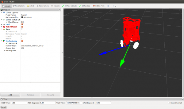
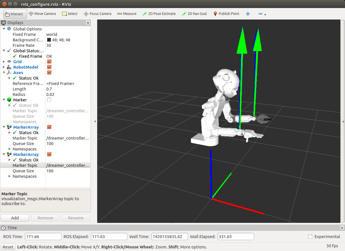
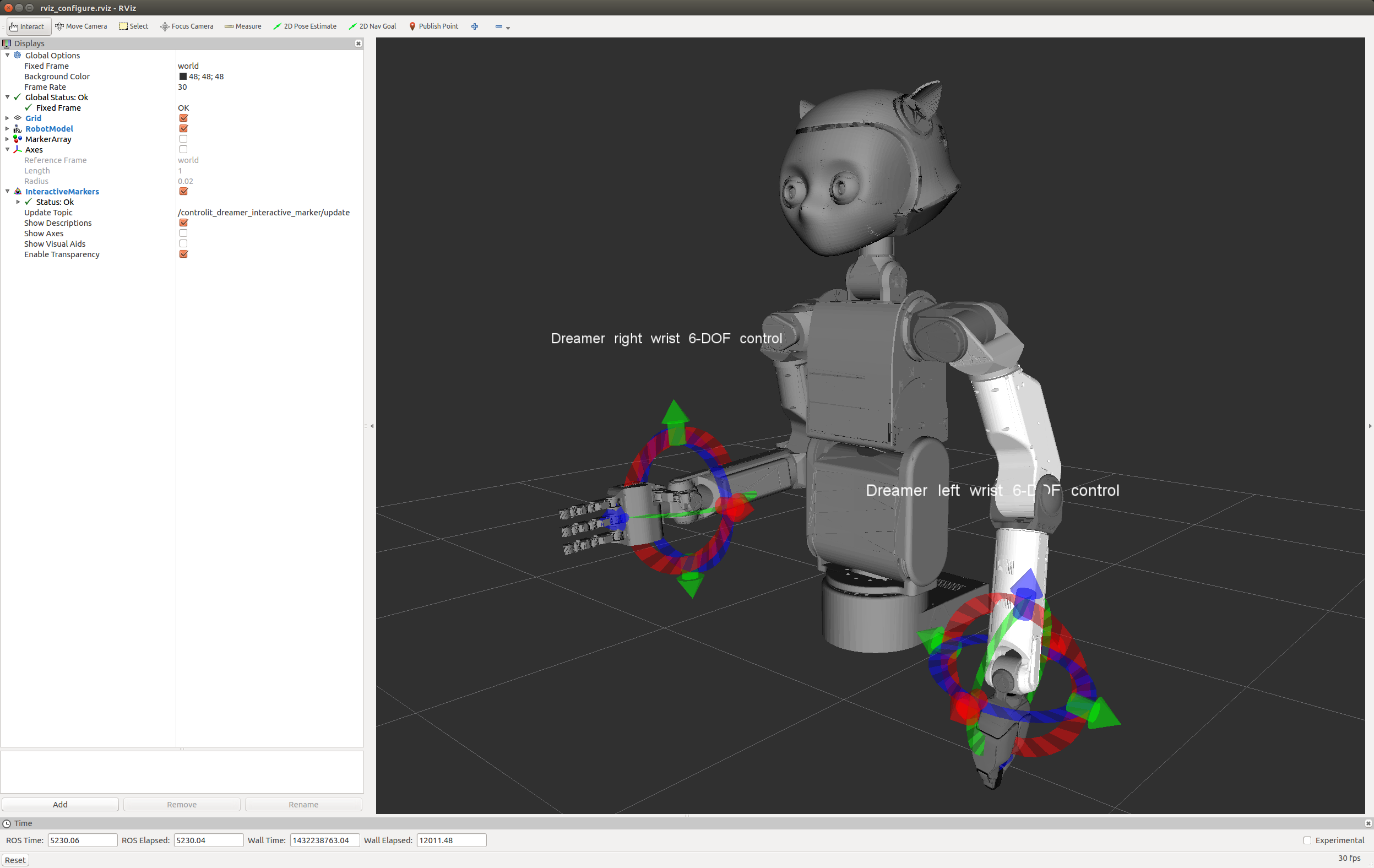
Figure 20 shows visualizations of the actual and desired center of pressures and the current center of mass projected onto the ground. This information is useful to visually determine the stability of the current posture.
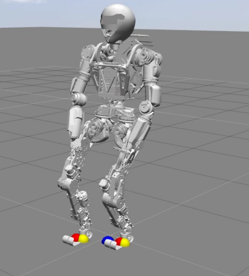
ROS service-based introspection capabilities. Table 8 lists the various service-based controller introspection capabilities that are provided by ControlIt!. These services can be called by external processes and are useful for integrating ControlIt! into a larger system. All services are namespaced by the controller’s name enabling multiple instances of ControlIt! to simultaneously exist.
| Service | Description |
|---|---|
| diagnostics/getActuableJointIndices | Provides the order of every actuable joint in the robot model (omits joints that are real but not actuable) |
| diagnostics/getCmdJointIndices | Provides the order of the joints in the command issued by ControlIt! to the robot. |
| diagnostics/getConstraintJacobianMatrices | Provides the Jacobian matrices belonging to the constraints in the constraint set. |
| diagnostics/getConstraintParameters | Provides a list of every constraint parameter and its current value. |
| diagnostics/getControlItParameters | Provides the current values of the ControlIt! parameters defined in Appendix A.2. |
| diagnostics/getControllerConfiguration | Provides the current state of the compound task and constraint set. |
| diagnostics/getRealJointIndices | Provides the order of every real joint in the robot model. |
| diagnostics/getTaskParameters | Provides a list of every task parameter is its current value. |
ROS topic-based introspection capabilities. Table 9 lists the various topic-based controller introspection capabilities that are provided by ControlIt!. These topics can be subscribed to by external processes and are useful for integrating ControlIt! into a larger system. All topics are namespaced by the controller’s name enabling multiple instances of ControlIt! to simultaneously exist.
| Service | Description |
|---|---|
| diagnostics/RTTCommLatency | Publishes the latest round-trip communication time between ControlIt! and the joint-level controllers. This is done by transmitting sequence numbers to the joint-level controllers, which are reflected back through the joint state data. ControlIt! monitors the time between transmitting a particular sequence number and receiving it back. |
| diagnostics/command | Publishes the latest command issued by ControlIt! to the robot. |
| diagnostics/errors | Publishes any run-time errors that are encountered. An example error is when the command includes NaN values. |
| diagnostics/gravityVector | Publishes the current gravity compensation vector. |
| diagnostics/jointState | Publishes the latest joint state information. |
| diagnostics/modelLatency | Publishes the “staleness” of the currently active model. The model latency is the time since the model was last updated. |
| diagnostics/servoComputeLatency | Publishes the amount of time it took to execute the computations within one cycle of the servo loop. |
| diagnostics/servoFrequency | Publishes the instantaneous servo frequency. |
| diagnostics/warnings | Publishes any run-time warnings that are encountered. An example warning is when the joint position or velocity exceeds expected limits. |
Appendix D ControlIt! Configuration File
ControlIt! enables user to specify the controller configuration using a YAML configuration file. The syntax of this file is shown below. By enabling YAML-based configuration, ControlIt! can be made to work with a wide variety of applications without modifying the source code and recompiling.
Task specification:
tasks:
  - name: [task name]  # user defined
    type: [task type]  # must match plugin name
    ... # task-specific parameters and their values
  ... # additional tasks
Constraint specification:
constraints:
  - name: [constraint name]  # user defined
    type: [constraint type]  # must match plugin name
    ... # constraint-specific parameters and their values
  ... # additional constraints
Compound task specification:
compound_task:
  - name: [task name]
    priority: [priority level]
    operational_state: [enable or disable]
  ... # additional tasks
Constraint set specification:
constraint_set:
  - name: [constraint name]
    type: [constraint type]
    operational_state: [enable or disable]
  ... # additional constraints
Binding Specification:
bindings:
  - parameter: [parameter name] # must match real parameter name
    direction: [input or output]
    topic: [topic name]
    transport_type: [transport type] # must match plugin name
    properties:
     - [transport-specific property]
     ... # additional transport-specific properties
  ... # additional bindings
Event Specification:
 events:
   - name: [event name] # user defined
     expression: [logical expression over parameters]
   ... # additional events
Appendix E Controller Gains
The following tables provide the gains used by the various controllers in the product disassembly application using Dreamer. The negative joint position controller gains are strange but were configured as such by Meka Robotics, the robot’s manufacturer (Meka Robotics has since been bought by Google). We don’t know for sure why some gains are negative since we are unable to access the details of the joint-level controllers. It’s possible that the direction of the encoder is opposite of the motor resulting in the need for negative gains. Regardless, these were the functioning settings used in the development and testing of ControlIt! on Dreamer.
The reason why the left and right arms have different gains is because the left arm is about three years newer than the right arm and internally the mechatronics of the left arm are significantly different from that of the right arm.
| Controller | Kp | Ki | Kd |
|---|---|---|---|
| torso_lower_pitch | -3 | 0 | 0 |
| left_shoulder_extensor | 10 | 1 | 0 |
| left_shoulder_abductor | 10 | 1 | 0 |
| left_shoulder_rotator | 10 | 1 | 0 |
| left_elbow | 10 | 1 | 0 |
| left_wrist_rotator | 50 | 0 | 0 |
| left_wrist_pitch | 15 | 0 | 1 |
| left_wrist_yaw | 15 | 0 | 1 |
| right_shoulder_extensor | 7 | 0 | 0 |
| right_shoulder_abductor | 6 | 0 | 0 |
| right_shoulder_rotator | 5 | 0 | 0 |
| right_elbow | 5 | 0 | 0 |
| right_wrist_rotator | -3 | 0 | 1 |
| right_wrist_pitch | -15 | 0 | -1 |
| right_wrist_yaw | -15 | 0 | -1 |
| Task | Kp | Ki | Kd |
|---|---|---|---|
| Joint Position Task | 60 | 0 | 3 |
| Left Hand Orientation | 60 | 0 | 3 |
| Right Hand Orientation | 60 | 0 | 3 |
| Left Hand Position | 64 | 0 | 3 |
| Right Hand Position | 64 | 0 | 3 |
Appendix F Example Application Code
Figure 21 contains an example code fragment from the product disassembly . The application is written in the Python programming language, though any programming language supported by ROS could be used including C++. The code fragment shows how the Cartesian position trajectory is generated for moving the right hand into a position where it can grab the metal tube. Lines 548-552 specify the Cartesian (x, y, z) waypoints that the hand is expected to traverse. For brevity, only one waypoint is shown. Line 555 creates a cubic-spline interpolator, which is used on line 559 to generate the intermediate points between the waypoints. The while loop starting on line 564 obtains the current goal Cartesian position based on the elapsed time (line 572) and transmits this goal via a ROS topic (line 576). The goal parameter of the right hand Cartesian position task within ControlIt! is bound to this ROS topic enabling ControlIt! to follow the desired Cartesian trajectory. The trajectory is transmitted at 100Hz, based on line 579. Once the trajectory is done, line 583 issues a command to close the fingers in the right hand is issued via another bound ROS topic.
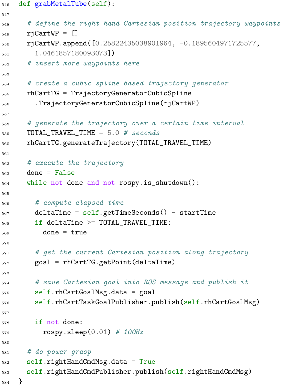
Appendix G ControlIt! SMACH FSM Integration
The following screenshot is a visualization of the product disassembly finite state machine provided by ROS SMACH Visualizer. It is updated in real-time as the application in running. This particular screenshot shows that Dreamer is in the “GrabValveState” which is when her left gripper is being positioned to grab the valve.
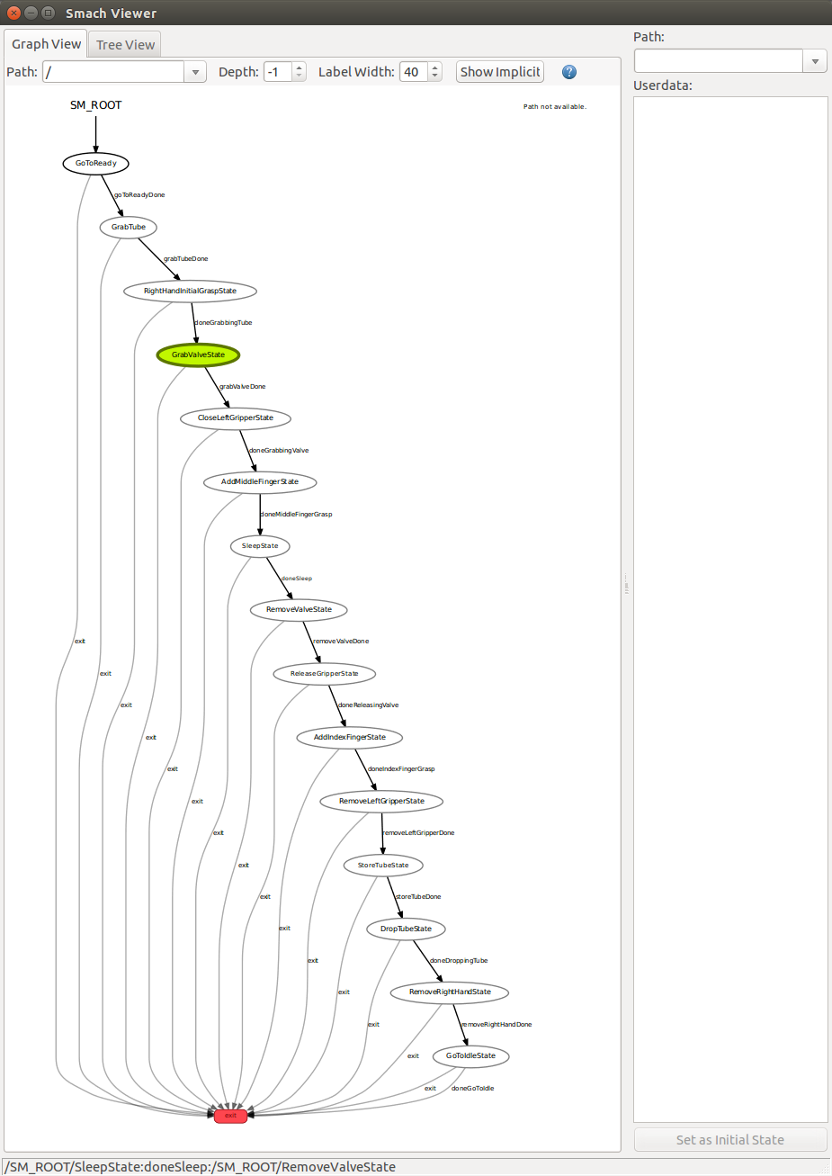
References
- [1] L. Sentis and O. Khatib, “Synthesis of whole-body behaviors through hierarchical control of behavioral primitives,” International Journal of Humanoid Robotics, pp. 505–518, 2005.
- [2] L. Sentis, “Synthesis and control of whole-body behaviors in humanoid systems,” Ph.D. dissertation, Stanford University, 2007, supervised by Oussama Khatib, http://www.me.utexas.edu/~lsentis/files/Thesis-Sentis-2007.pdf.
- [3] L. Sentis, J. Park, and O. Khatib, “Compliant control of multicontact and center-of-mass behaviors in humanoid robots,” IEEE Transactions on Robotics, vol. 26, no. 4, pp. 483–501, 6 2010, http://www.me.utexas.edu/~lsentis/files/tro-2010.pdf.
- [4] IEEE Robotics and Automation Society. (2015) Whole body control technical committee. [Online; accessed 13-February-2015]. [Online]. Available: http://www.ieee-ras.org/whole-body-control
- [5] Ioan A. Sucan and Sachin Chitta. (2015) Moveit! [Online; accessed 13-February-2015]. [Online]. Available: http://moveit.ros.org/
- [6] Robot Operating System. (2015) Ros control. [Online; accessed 13-February-2015]. [Online]. Available: http://wiki.ros.org/ros_control
- [7] F. Aghili, “A unified approach for inverse and direct dynamics of constrained multibody systems based on linear projection operator: applications to control and simulation,” Robotics, IEEE Transactions on, vol. 21, no. 5, pp. 834–849, Oct 2005.
- [8] S.-H. Hyon, J. G. Hale, and G. Cheng, “Full-body compliant human – humanoid interaction: Balancing in the presence of unknown external forces,” Robotics, IEEE Transactions on, vol. 23, no. 5, pp. 884–898, Oct 2007, http://dx.doi.org/10.1109/TRO.2007.904896.
- [9] J. Nakanishi, M. Mistry, and S. Schaal, “Inverse dynamics control with floating base and constraints,” in Robotics and Automation, 2007 IEEE International Conference on, April 2007, pp. 1942–1947, http://dx.doi.org/10.1109/ROBOT.2007.363606.
- [10] M. Mistry, J. Buchli, and S. Schaal, “Inverse dynamics control of floating base systems using orthogonal decomposition,” in Robotics and Automation (ICRA), 2010 IEEE International Conference on, May 2010, pp. 3406–3412.
- [11] K. Nagasaka, Y. Kawanami, S. Shimizu, T. Kito, T. Tsuboi, A. Miyamoto, T. Fukushima, and H. Shimomura, “Whole-body cooperative force control for a two-armed and two-wheeled mobile robot using generalized inverse dynamics and idealized joint units,” in Robotics and Automation (ICRA), 2010 IEEE International Conference on, May 2010, pp. 3377–3383.
- [12] M. Mistry and L. Righetti, “Operational space control of constrained and underactuated systems,” in Proceedings of Robotics: Science and Systems, Los Angeles, CA, USA, June 2011.
- [13] L. Righetti, J. Buchli, M. Mistry, and S. Schaal, “Inverse dynamics control of floating-base robots with external constraints: A unified view,” in Robotics and Automation (ICRA), 2011 IEEE International Conference on, May 2011, pp. 1085–1090, http://dx.doi.org/10.1109/ICRA.2011.5980156.
- [14] L. Righetti and S. Schaal, “Quadratic programming for inverse dynamics with optimal distribution of contact forces,” in Humanoid Robots (Humanoids), 2012 12th IEEE-RAS International Conference on, Nov 2012, pp. 538–543, http://dx.doi.org/10.1109/HUMANOIDS.2012.6651572.
- [15] K. Wakita, J. Huang, P. Di, K. Sekiyama, and T. Fukuda, “Human-walking-intention-based motion control of an omnidirectional-type cane robot,” Mechatronics, IEEE/ASME Transactions on, vol. 18, no. 1, pp. 285–296, Feb 2013, http://dx.doi.org/10.1109/TMECH.2011.2169980.
- [16] S.-H. Lee and A. Goswami, “A momentum-based balance controller for humanoid robots on non-level and non-stationary ground,” Autonomous Robots, vol. 33, no. 4, pp. 399–414, 2012. [Online]. Available: http://dx.doi.org/10.1007/s10514-012-9294-z
- [17] J. Salini, “Dynamic control for the task/posture coordination of humanoids: Towards synthesis of complex activities,” Ph.D. dissertation, Universit Pierre et Marie Curie, 2013.
- [18] F. L. Moro, M. Gienger, A. Goswami, N. G. Tsagarakis, and D. G. Caldwell, “An attractor-based whole-body motion control (wbmc) system for humanoid robots,” in Humanoid Robots (Humanoids), 2013 13th IEEE-RAS International Conference on, 2013, pp. 42–49.
- [19] L. Righetti, J. Buchli, M. Mistry, M. Kalakrishnan, and S. Schaal, “Optimal distribution of contact forces with inverse-dynamics control,” The International Journal of Robotics Research, vol. 32, no. 3, pp. 280–298, 2013. [Online]. Available: http://ijr.sagepub.com/content/32/3/280
- [20] L. Saab, O. Ramos, F. Keith, N. Mansard, P. Soueres, and J. Fourquet, “Dynamic whole-body motion generation under rigid contacts and other unilateral constraints,” Robotics, IEEE Transactions on, vol. 29, no. 2, pp. 346–362, April 2013.
- [21] S. Lengagne, J. Vaillant, E. Yoshida, and A. Kheddar, “Generation of whole-body optimal dynamic multi-contact motions,” Int. J. Rob. Res., vol. 32, no. 9-10, pp. 1104–1119, Aug. 2013. [Online]. Available: http://dx.doi.org/10.1177/0278364913478990
- [22] T. Koolen, “Force control for a humanoid robot using momentum and instantaneous capture point dynamics,” in Robotics and Automation (ICRA), 2013 IEEE International Conference on, 2013.
- [23] B. Henze, C. Ott, and M. Roa, “Posture and balance control for humanoid robots in multi-contact scenarios based on model predictive control,” in Intelligent Robots and Systems (IROS 2014), 2014 IEEE/RSJ International Conference on, Sept 2014, pp. 3253–3258.
- [24] L. Righetti, M. Kalakrishnan, P. Pastor, J. Binney, J. Kelly, R. Voorhies, G. Sukhatme, and S. Schaal, “An autonomous manipulation system based on force control and optimization,” Autonomous Robots, vol. 36, no. 1-2, pp. 11–30, 2014. [Online]. Available: http://dx.doi.org/10.1007/s10514-013-9365-9
- [25] A. Escande, N. Mansard, and P.-B. Wieber, “Hierarchical quadratic programming: Fast online humanoid-robot motion generation,” The International Journal of Robotics Research, vol. 33, no. 7, pp. 1006–1028, 2014.
- [26] S. Hyon, “A motor control strategy with virtual musculoskeletal systems for compliant anthropomorphic robots,” Mechatronics, IEEE/ASME Transactions on, vol. 14, no. 6, pp. 677–688, Dec 2009, http://dx.doi.org/10.1109/TMECH.2009.2033117.
- [27] L. Sentis, J. Peterson, and R. Philippsen, “Implementation and stability analysis of prioritized whole-body compliant controllers on a wheeled humanoid robot in uneven terrains,” Autonomous Robots, vol. 35, no. 4, pp. 301–319, 2013, http://www.me.utexas.edu/~lsentis/files/sentis-petersen-philippsen--auro-2013-2.pdf.
- [28] I. Mizuuchi, Y. Nakanishi, Y. Sodeyama, Y. Namiki, T. Nishino, N. Muramatsu, J. Urata, K. Hongo, T. Yoshikai, and M. Inaba, “An advanced musculoskeletal humanoid kojiro,” in Humanoid Robots, 2007 7th IEEE-RAS International Conference on, Nov 2007, pp. 294–299.
- [29] Y. Nakanishi, S. Ohta, T. Shirai, Y. Asano, T. Kozuki, Y. Kakehashi, H. Mizoguchi, T. Kurotobi, Y. Motegi, K. Sasabuchi, J. Urata, K. Okada, I. Mizuuchi, and M. Inaba, “Design approach of biologically-inspired musculoskeletal humanoids,” Int. Journal of Advanced Robotic Systems, vol. 10, no. 216, 2013, http://www.intechopen.com/journals/international_journal_of_advanced_robotic_systems/design-approach-of-biologically-inspired-musculoskeletal-humanoids.
- [30] A. Dietrich, C. Ott, and A. Albu-Schaffer, “Multi-objective compliance control of redundant manipulators: Hierarchy, control, and stability,” in Intelligent Robots and Systems (IROS), 2013 IEEE/RSJ International Conference on, Nov 2013, pp. 3043–3050.
- [31] C. Ott, M. Roa, and G. Hirzinger, “Posture and balance control for biped robots based on contact force optimization,” in Humanoid Robots (Humanoids), 2011 11th IEEE-RAS International Conference on, Oct 2011, pp. 26–33.
- [32] J. Englsberger, C. Ott, and A. Albu-Schaffer, “Three-dimensional bipedal walking control using divergent component of motion,” in Intelligent Robots and Systems (IROS), 2013 IEEE/RSJ International Conference on, Nov 2013, pp. 2600–2607.
- [33] F. Moro, N. Tsagarakis, and D. Caldwell, “Walking in the resonance with the COMAN robot with trajectories based on human kinematic motion primitives (kMPs),” Autonomous Robots, vol. 36, no. 4, pp. 331–347, 2014. [Online]. Available: http://dx.doi.org/10.1007/s10514-013-9357-9
- [34] E. Whitman and C. Atkeson, “Control of instantaneously coupled systems applied to humanoid walking,” in Humanoid Robots (Humanoids), 2010 10th IEEE-RAS International Conference on, Dec 2010, pp. 210–217.
- [35] M. Hutter, M. Bloesch, J. Buchli, C. Semini, S. Bazeille, L. Righetti, and J. Bohg, “AGILITY - dynamic full body locomotion and manipulation with autonomous legged robots,” in Safety, Security, and Rescue Robotics (SSRR), 2013 IEEE International Symposium on, Oct 2013, pp. 1–4.
- [36] K. Hirai, M. Hirose, Y. Haikawa, and T. Takenaka, “The development of honda humanoid robot,” in Robotics and Automation, 1998. Proceedings. 1998 IEEE International Conference on, vol. 2, May 1998, pp. 1321–1326 vol.2.
- [37] S. Kajita, F. Kanehiro, K. Kaneko, K. Fujiwara, K. Harada, K. Yokoi, and H. Hirukawa, “Resolved momentum control: humanoid motion planning based on the linear and angular momentum,” in Intelligent Robots and Systems, 2003. (IROS 2003). Proceedings. 2003 IEEE/RSJ International Conference on, vol. 2, Oct 2003, pp. 1644–1650 vol.2.
- [38] K. Bouyarmane and A. Kheddar, “On the dynamics modeling of free-floating-base articulated mechanisms and applications to humanoid whole-body dynamics and control,” in Humanoid Robots (Humanoids), 2012 12th IEEE-RAS International Conference on, Nov 2012, pp. 36–42.
- [39] T. Ohmichi, S. Hosaka, M. Nishihara, T. Ibe, A. Okino, J. Nakayama, T. Miida, and M. Ishida, “Development of the multi-function robot for the containment vessel of the nuclear plant,” in International conference on advanced robotics, vol. 19, no. 20, 1985.
- [40] S. Hirose, A. Morishima, S. Tukagosi, T. Tsumaki, and H. Monobe, “Design of practical snake vehicle: articulated body mobile robot KR-II,” in Advanced Robotics, 1991. ’Robots in Unstructured Environments’, 91 ICAR., Fifth International Conference on, June 1991, pp. 833–838 vol.1.
- [41] N. Eiji and N. Sei, “Leg-wheel robot: a futuristic mobile platform for forestry industry,” in Advanced Robotics, 1993. Can Robots Contribute to Preventing Environmental Deterioration? Proceedings, 1993 IEEE/Tsukuba International Workshop on, Nov 1993, pp. 109–112.
- [42] O. Matsumoto, S. Kajita, K. Tani, and M. Oooto, “A four-wheeled robot to pass over steps by changing running control modes,” in Robotics and Automation, 1995. Proceedings., 1995 IEEE International Conference on, vol. 2, May 1995, pp. 1700–1706 vol.2.
- [43] T. Asfour, K. Berns, and R. Dillmann, “The humanoid robot ARMAR: Design and control,” in IN IEEE/APS INTL CONFERENCE ON HUMANOID ROBOTS, 2000, pp. 7–8.
- [44] D. Katz, E. Horrell, Y. Yang, B. Burns, T. Buckley, A. Grishkan, V. Zhylkovskyy, O. Brock, and E. Learned-Miller, “The umass mobile manipulator uman: An experimental platform for autonomous mobile manipulation.” in Workshop on Manipulation in Human Environments at Robotics: Science and systems., 2006.
- [45] C. Loughlin, A. Albu‐Schäffer, S. Haddadin, C. Ott, A. Stemmer, T. Wimböck, and G. Hirzinger, “The DLR lightweight robot: design and control concepts for robots in human environments,” Industrial Robot: An International Journal, vol. 34, no. 5, pp. 376–385, 2007. [Online]. Available: http://dx.doi.org/10.1108/01439910710774386
- [46] C. Borst, C. Ott, T. Wimbock, B. Brunner, F. Zacharias, B. Bauml, U. Hillenbrand, S. Haddadin, A. Albu-Schäffer, and G. Hirzinger, “A humanoid upper body system for two-handed manipulation,” in Robotics and Automation, 2007 IEEE International Conference on, April 2007, pp. 2766–2767.
- [47] D. Theobold, J. Ornstein, J. G. Nichol, and S. E. Kullberg, “Mobile robot platform google patents,” US Patent, 7 2008, 7,348,747.
- [48] G. Freitas, F. Lizarralde, L. Hsu, and N. Reis, “Kinematic reconfigurability of mobile robots on irregular terrains,” in Robotics and Automation, 2009. ICRA ’09. IEEE International Conference on, May 2009, pp. 1340–1345.
- [49] M. Beetz, L. Mosenlechner, and M. Tenorth, “CRAM – a cognitive robot abstract machine for everyday manipulation in human environments,” in Intelligent Robots and Systems (IROS), 2010 IEEE/RSJ International Conference on, Oct 2010, pp. 1012–1017.
- [50] H. Iwata and S. Sugano, “Design of human symbiotic robot TWENDY-ONE, year=2009, month=May, pages=580-586, keywords=control system synthesis;human-robot interaction;humanoid robots;manipulators;mobile robots;service robots;TWENDY-ONE robot;anthropomorphic dual hand;compact passive mechanism;dexterity function;elderly person physical support;human symbiotic robot design;kitchen support robot;mobility function;omni-wheeled vehicle;physical support;Anthropomorphism;Humans;Layout;Manipulators;Robots;Safety;Senior citizens;Skin;Symbiosis;Vehicles, doi=10.1109/ROBOT.2009.5152702, issn=1050-4729,” in Robotics and Automation, 2009. ICRA ’09. IEEE International Conference on.
- [51] U. Reiser, C. Connette, J. Fischer, J. Kubacki, A. Bubeck, F. Weisshardt, T. Jacobs, C. Parlitz, M. Hagele, and A. Verl, “Care-o-bot 3 - creating a product vision for service robot applications by integrating design and technology,” in Intelligent Robots and Systems, 2009. IROS 2009. IEEE/RSJ International Conference on, Oct 2009, pp. 1992–1998.
- [52] C.-H. King, T. L. Chen, A. Jain, and C. C. Kemp, “Towards an assistive robot that autonomously performs bed baths for patient hygiene.” in IROS. IEEE, 2010, pp. 319–324. [Online]. Available: http://dblp.uni-trier.de/db/conf/iros/iros2010.html#KingCJK10
- [53] B. Stephens and C. Atkeson, “Dynamic balance force control for compliant humanoid robots,” in Intelligent Robots and Systems (IROS), 2010 IEEE/RSJ International Conference on, Oct 2010, pp. 1248–1255.
- [54] M. Stilman, J. Olson, and W. Gloss, “Golem krang: Dynamically stable humanoid robot for mobile manipulation,” in Robotics and Automation (ICRA), 2010 IEEE International Conference on, May 2010, pp. 3304–3309.
- [55] W. Meeussen, M. Wise, S. Glaser, S. Chitta, C. McGann, P. Mihelich, E. Marder-Eppstein, M. Muja, V. Eruhimov, T. Foote, J. Hsu, R. Rusu, B. Marthi, G. Bradski, K. Konolige, B. Gerkey, and E. Berger, “Autonomous door opening and plugging in with a personal robot,” in Robotics and Automation (ICRA), 2010 IEEE International Conference on, May 2010, pp. 729–736.
- [56] S. Hart, J. Yamokoski, and M. Diftler, “Robonaut 2: A new platform for human-centered robot learning,” Robotics Science and Systems, 2011.
- [57] B. J. Stephens, “Push recovery control for force-controlled humanoid robots,” Ph.D. dissertation, Carnegie Mellon University, 2011.
- [58] F. Moro, N. Tsagarakis, and D. Caldwell, “A human-like walking for the COmpliant huMANoid COMAN based on CoM trajectory reconstruction from kinematic motion primitives,” in Humanoid Robots (Humanoids), 2011 11th IEEE-RAS International Conference on, Oct 2011, pp. 364–370.
- [59] N. Tsagarakis, Z. Li, J. Saglia, and D. Caldwell, “The design of the lower body of the compliant humanoid robot “cCub”,” in Robotics and Automation (ICRA), 2011 IEEE International Conference on, May 2011, pp. 2035–2040.
- [60] S. Bertrand and J. Pratt, “Momentum-based control framework: application to the humanoid robots atlas and valkyrie,” in IROS 2014 Workshop on Whole-Body Control for Robots in the Real World, 2014.
- [61] A. Herzog, L. Righetti, F. Grimminger, P. Pastor, and S. Schaal, “Balancing experiments on a torque-controlled humanoid with hierarchical inverse dynamics,” in Proceeedings of 2014 IEEE/RSJ International Conference on Intelligent Robots and Systems, 2014.
- [62] ——, “Momentum-based balance control for torque-controlled humanoids,” CoRR, vol. abs/1305.2042, 2013. [Online]. Available: http://arxiv.org/abs/1305.2042
- [63] M. Hutter, C. Gehring, M. Bloesch, M. A. Hoepflinger, C. D. Remy, and R. Siegwart, “StarlETH: A compliant quadrupedal robot for fast, efficient, and versatile locomotion,” in 15th International Conference on Climbing and Walking Robot - CLAWAR 2012, 2012.
- [64] M. Hutter, H. Sommer, C. Gehring, M. Hoepflinger, M. Bloesch, and R. Siegwart, “Quadrupedal locomotion using hierarchical operational space control,” The International Journal of Robotics Research, 2014.
- [65] M. Fuchs, C. Borst, P. Giordano, A. Baumann, E. Kraemer, J. Langwald, R. Gruber, N. Seitz, G. Plank, K. Kunze, R. Burger, F. Schmidt, T. Wimboeck, and G. Hirzinger, “Rollin’ justin - design considerations and realization of a mobile platform for a humanoid upper body,” in Robotics and Automation, 2009. ICRA ’09. IEEE International Conference on, May 2009, pp. 4131–4137.
- [66] C. Semini, N. G. Tsagarakis, E. Guglielmino, M. Focchi, F. Cannella, and D. G. Caldwell, “Design of HyQ – a hydraulically and electrically actuated quadruped robot,” in Proceedings of the Institution of Mechanical Engineers, Part I: Journal of Systems and Control Engineering, vol. 225, no. 6, August 2011, pp. 831–849.
- [67] R. Tellez, F. Ferro, S. Garcia, E. Gomez, E. Jorge, D. Mora, D. Pinyol, J. Oliver, O. Torres, J. Velazquez, and D. Faconti, “Reem-B: An autonomous lightweight human-size humanoid robot,” in Humanoid Robots, 2008. Humanoids 2008. 8th IEEE-RAS International Conference on, Dec 2008, pp. 462–468.
- [68] An Open Source Extensible Software Package to Create Whole-Body Compliant Skills in Personal Mobile Manipulators, 2011, http://www.me.utexas.edu/~lsentis/files/iros-wbc-2011.pdf.
- [69] Human Centered Robotics Laboratory at the University of Texas at Austin. (2015) Uta-wbc. [Online; accessed 13-February-2015]. [Online]. Available: https://github.com/lsentis/uta-wbc-dreamer
- [70] G. T. Heineman and W. T. Councill, Eds., Component-based Software Engineering: Putting the Pieces Together. Boston, MA, USA: Addison-Wesley Longman Publishing Co., Inc., 2001.
- [71] C. Szyperski, Component Software: Beyond Object-Oriented Programming, 2nd ed. Boston, MA, USA: Addison-Wesley Longman Publishing Co., Inc., 2002.
- [72] F. Kanehiro, K. Fujiwara, S. Kajita, K. Yokoi, K. Kaneko, H. Hirukawa, Y. Nakamura, and K. Yamane, “Open architecture humanoid robotics platform,” in Robotics and Automation, 2002. Proceedings. ICRA ’02. IEEE International Conference on, vol. 1, 2002, pp. 24–30 vol.1.
- [73] H. Hirukawa, F. Kanehiro, K. Kaneko, S. Kajita, K. Fujiwara, Y. Kawai, F. Tomita, S. Hirai, K. Tanie, T. Isozumi, K. Akachi, T. Kawasaki, S. Ota, K. Yokoyama, H. Handa, Y. Fukase, J. ichiro Maeda, Y. Nakamura, S. Tachi, and H. Inoue, “Humanoid robotics platforms developed in {HRP},” Robotics and Autonomous Systems, vol. 48, no. 4, pp. 165 – 175, 2004, humanoids 2003. [Online]. Available: http://www.sciencedirect.com/science/article/pii/S0921889004000946
- [74] N. Ando, T. Suehiro, K. Kitagaki, T. Kotoku, and W.-K. Yoon, “RT-middleware: distributed component middleware for rt (robot technology),” in Intelligent Robots and Systems, 2005. (IROS 2005). 2005 IEEE/RSJ International Conference on, Aug 2005, pp. 3933–3938.
- [75] Orocos. (2015) Orocos toolchain. [Online; accessed 13-February-2015]. [Online]. Available: http://www.orocos.org/toolchain
- [76] G. Metta, P. Fitzpatrick, and L. Natale, “YARP: Yet another robot platform,” International Journal on Advanced Robotics Systems, vol. 3, no. 1, 2006.
- [77] Robot Operating System. (2015) Ros. [Online; accessed 13-February-2015]. [Online]. Available: http://www.ros.org/
- [78] M. Quigley, K. Conley, B. Gerkey, J. Faust, T. Foote, J. Leibs, R. Wheeler, and A. Y. Ng, “ROS: an open-source robot operating system,” ICRA workshop on open source software, vol. 3, no. 3.2, p. 5, 2009.
- [79] I. A. Nesnas, R. Simmons, D. Gaines, C. Kunz, A. Dias-Caldron, T. Estlin, R. Madison, J. Guineau, M. McHenry, I. Shu, and D. Apfelbaum, “CLARAty: Challenges and steps toward reusable robotic software,” Int. Journal of Advanced Robotic Systems, vol. 3, no. 1, 2006.
- [80] I. A. Nesnas, “CLARAty: A collaborative software for advancing robotic technologies,” in Proc. of NASA Science and Technology Conference, June 2007.
- [81] G. Hirzinger and B. Bauml, “Agile robot development (aRD): A pragmatic approach to robotic software,” in Intelligent Robots and Systems, 2006 IEEE/RSJ International Conference on, Oct 2006, pp. 3741–3748.
- [82] Microblx. (2014) Microblx - a lightweight, dynamic, reflective, hard real-time safe function block framework. [Online; accessed 13-February-2015]. [Online]. Available: http://www.microblx.org/
- [83] M. Klotzbuecher and H. Bruyninckx, “microblx: a reflective, real-time safe, embedded function block framework,” in 15th Real Time Linux Workshop, October 2013.
- [84] RoCoCo Laboratory. (2015) Open robot development kit. [Online; accessed 13-February-2015]. [Online]. Available: http://openrdk.sourceforge.net/
- [85] D. Calisi, A. Censi, L. Iocchi, and D. Nardi, “OpenRDK: A modular framework for robotic software development,” in Intelligent Robots and Systems, 2008. IROS 2008. IEEE/RSJ International Conference on, Sept 2008, pp. 1872–1877.
- [86] D. Calisi, A. Censi, L. Locchi, and D. Nardi, “Design choices for modular and flexible robotic software development: the OpenRDK viewpoint,” Journal of Software Engineering for Robotics, vol. 3, no. 1, 2012, http://joser.unibg.it/index.php?journal=joser&page=article&op=view&path%5B%5D=48.
- [87] M. Munich, J. Ostrowski, and P. Pirjanian, “ERSP: a software platform and architecture for the service robotics industry,” in Intelligent Robots and Systems, 2005. (IROS 2005). 2005 IEEE/RSJ International Conference on, Aug 2005, pp. 460–467.
- [88] Dipartimento Di Scienze e Tecnologie Aerospaziali del Politecnico di Milano. (2015) Real-time application interface. [Online; accessed 13-February-2015]. [Online]. Available: https://www.rtai.org/
- [89] A. R. Tsouroukdissian, “Ros control, an overview,” in ROSCon 2014, September 2014.
- [90] J. Bohren. (2015) Conman - a robot state estimator and controller manager for use in orocos rtt and ros. [Online; accessed 13-February-2015]. [Online]. Available: https://github.com/jbohren/conman
- [91] Orocos Wiki. (2015) itasc (instantaneous task specification using constraints) website. [Online; accessed 13-February-2015]. [Online]. Available: http://www.orocos.org/wiki/orocos/itasc-wiki
- [92] J. De Schutter, T. De Laet, J. Rutgeerts, W. Decré, R. Smits, E. Aertbeliën, K. Claes, and H. Bruyninckx, “Constraint-based task specification and estimation for sensor-based robot systems in the presence of geometric uncertainty,” The International Journal of Robotics Research, vol. 26, no. 5, pp. 433–455, 2007. [Online]. Available: http://ijr.sagepub.com/content/26/5/433.abstract
- [93] W. Decre, R. Smits, H. Bruyninckx, and J. De Schutter, “Extending iTaSC to support inequality constraints and non-instantaneous task specification,” in Robotics and Automation, 2009. ICRA ’09. IEEE International Conference on, May 2009, pp. 964–971.
- [94] W. Decre, H. Bruyninckx, and J. De Schutter, “Extending the iTaSC constraint-based robot task specification framework to time-independent trajectories and user-configurable task horizons,” in Robotics and Automation (ICRA), 2013 IEEE International Conference on, May 2013, pp. 1941–1948.
- [95] Rock Robotics. (2015) Rock - the robot construction kit. [Online; accessed 13-February-2015]. [Online]. Available: http://rock-robotics.org/stable/
- [96] B. Brunner, K. Landzettel, G. Schreiber, B. Stinmetz, and G. Girzinger, “A universal task level ground control and programming system for space robot applications - the MARCO concept and its application to the ets vii project,” in Proc. of the 5th iSAIRAS Int. Symp. on Artifical Intelligence, Robotics, and Automation in Space, 1999.
- [97] S. Fleury, M. Herrb, and R. Chatila, “GenoM: a tool for the specification and the implementation of operating modules in a distributed robot architecture,” in Intelligent Robots and Systems, 1997. IROS ’97., Proceedings of the 1997 IEEE/RSJ International Conference on, vol. 2, Sep 1997, pp. 842–849 vol.2.
- [98] Willow Garage. (2015) Ecto - a c++/python computation graph framework. [Online; accessed 13-February-2015]. [Online]. Available: http://plasmodic.github.io/ecto/
- [99] S. Hart, P. Dinh, J. Yamokoski, B. Wightman, and N. Radford, “Robot task commander: A framework and IDE for robot application development,” in Intelligent Robots and Systems (IROS 2014), 2014 IEEE/RSJ International Conference on, Sept 2014, pp. 1547–1554.
- [100] R. Arkin and R. Murphy, “Autonomous navigation in a manufacturing environment,” Robotics and Automation, IEEE Transactions on, vol. 6, no. 4, pp. 445–454, Aug 1990.
- [101] R. Alami, R. Chatila, S. Fleury, M. Ghallab, and F. Ingrand, “An architecture for autonomy,” INTERNATIONAL JOURNAL OF ROBOTICS RESEARCH, vol. 17, pp. 315–337, 1998.
- [102] O. C. JENKINS and M. J. MATARIĆ, “Performance-derived behavior vocabularies: Data-driven acquisition of skills from motion,” International Journal of Humanoid Robotics, vol. 01, no. 02, pp. 237–288, 2004. [Online]. Available: http://www.worldscientific.com/doi/abs/10.1142/S0219843604000186
- [103] P. Pastor, H. Hoffmann, T. Asfour, and S. Schaal, “Learning and generalization of motor skills by learning from demonstration,” in Robotics and Automation, 2009. ICRA ’09. IEEE International Conference on, May 2009, pp. 763–768.
- [104] K. Kim, J.-Y. Lee, D. Choi, J.-M. Park, and B.-J. You, “Autonomous task execution of a humanoid robot using a cognitive model,” in Robotics and Biomimetics (ROBIO), 2010 IEEE International Conference on, Dec 2010, pp. 405–410.
- [105] C. Ott, B. Henze, and D. Lee, “Kinesthetic teaching of humanoid motion based on whole-body compliance control with interaction-aware balancing,” in Intelligent Robots and Systems (IROS), 2013 IEEE/RSJ International Conference on, Nov 2013, pp. 4615–4621.
- [106] R. Simmons and D. Apfelbaum, “A task description language for robot control,” in Intelligent Robots and Systems, 1998. Proceedings., 1998 IEEE/RSJ International Conference on, vol. 3, Oct 1998, pp. 1931–1937 vol.3.
- [107] D. Kortenkamp, R. Burridge, R. P. Bonasso, D. Schreckenghost, and M. B. Hudson, “An intelligent software architecture for semiautonomous robot control,” in In Autonomy Control Software Workshop, Autonomous Agents 99, 1999, pp. 36–43.
- [108] Martin Felis. (2015) Rigid body dynamics library. [Online; accessed 13-February-2015]. [Online]. Available: http://rbdl.bitbucket.org/
- [109] Robot Operating System. (2015) Ros pluginlib. [Online; accessed 13-February-2015]. [Online]. Available: http://wiki.ros.org/pluginlib
- [110] J. James. (2015) Ros shared memory interface. [Online; accessed 13-February-2015]. [Online]. Available: https://bitbucket.org/jraipxg/ros_shared_memory_interface
- [111] Ingo Berg. (2015) muparser - a fast math library. [Online; accessed 13-February-2015]. [Online]. Available: http://muparser.beltoforion.de/
- [112] Robot Operating System. (2014) Ros launch. [Online; accessed 13-February-2015]. [Online]. Available: http://wiki.ros.org/roslaunch
- [113] ——. (2015) Ros bag. [Online; accessed 13-February-2015]. [Online]. Available: http://wiki.ros.org/rosbag
- [114] Open Source Robotics Foundation. (2015) Gazebo simulator website. [Online; accessed 13-February-2015]. [Online]. Available: http://gazebosim.org/
- [115] Robot Operating System. (2015) Ros client libraries. [Online; accessed 13-February-2015]. [Online]. Available: http://wiki.ros.org/Client%20Libraries
- [116] N. A. Radford, P. Strawser, K. Hambuchen, J. S. Mehling, W. K. Verdeyen, S. Donnan, J. Holley, J. Sanchez, V. Nguyen, L. Bridgwater, R. Berka, R. Ambrose, C. McQuin, J. D. Yamokoski, S. Hart, R. Guo, A. Parsons, B. Wightman, P. Dinh, B. Ames, C. Blakely, C. Edmonson, B. Sommers, R. Rea, C. Tobler, H. Bibby, B. Howard, L. Nui, A. Lee, M. Conover, L. Truong, D. Chesney, R. P. Jr., G. Johnson, C.-L. Fok, N. Paine, L. Sentis, E. Cousineau, R. Sinnet, J. Lack, M. Powell, B. Morris, and A. Ames, “Valkyrie: NASA’s first bipedal humanoid robot,” Journal of Field Robotics, 10 2014, http://www.me.utexas.edu/~hcrl/publications/JFR-NASA-HCRL-Final.pdf.
- [117] D. Kim, Y. Zhao, G. Thomas, and L. Sentis, “Accessing whole-body operational space control in a point-foot series elastic biped: Balance on split terrain and undirected walking,” Arxive preprint, 2015. [Online]. Available: http://arxiv.org/abs/1501.02855
- [118] Y. Zhao, N. Paine, K. Kim, and L. Sentis, “Stability and performance limits of latency-prone distributed feedback controllers,” 2015, http://arxiv.org/pdf/1501.02854v1.pdf.
- [119] M. Johnson, B. Shrewsbury, S. Bertrand, T. Wu, D. Duran, M. Floyd, P. Abeles, D. Stephen, N. Mertins, A. Lesman, J. Carff, W. Rifenburgh, P. Kaveti, W. Straatman, J. Smith, M. Griffioen, B. Layton, T. de Boer, T. Koolen, P. Neuhaus, and J. Pratt, “Team IHMC’s lessons learned from the DARPA robotics challenge trials,” Journal of Field Robotics, vol. 32, no. 2, pp. 192–208, 2015. [Online]. Available: http://onlinelibrary.wiley.com/doi/10.1002/rob.21571/abstract
- [120] O. Khatib, “A unified approach for motion and force control of robot manipulators: The operational space formulation,” vol. RA-3, no. 1, pp. 43–53, February 1987.