Detection of spin torque magnetization dynamics through low frequency noise
Abstract
We present a comparative study of high frequency dynamics and low frequency noise in elliptical magnetic tunnel junctions with lateral dimensions under 100 nm presenting current-switching phenomena. The analysis of the high frequency oscillation modes with respect to the current reveals the onset of a steady-state precession regime for negative bias currents above , when the magnetic field is applied along the easy axis of magnetization. By the study of low frequency noise for the same samples, we demonstrate the direct link between changes in the oscillation modes with the applied current and the normalised low frequency (1/f) noise as a function of the bias current. These findings prove that low frequency noise studies could be a simple and powerful technique to investigate spin-torque based magnetization dynamics.
Oscillations known as a ferromagnetic resonance arise from the precessional motion of the magnetization of a ferromagnetic material (FM) when an external magnetic field is applied in the presence of microwave pump field perpendicular to it. Since magnetic tunnel junctions (MTJs) are composed of ferromagnetic electrodes, and exhibit the tunneling magnetoresistance effect Julliere (1975); Moodera et al. (1995); Miyazaki and Tezuka (1995), it is possible to detect magnetization dynamics through the measurement of frequency dependent votage noise power (typically up to a few tens of GHz) in DC biased MTJs (see the review Ralph and Stiles (2008)). In the regime where the current density applied to the MTJ is low, the resulting damped oscillatory modes are due to the external applied magnetic field and thermal fluctuations, referred to as thermal FMR (T-FMR). This effect is typically observed for applied current densities below Ralph and Stiles (2008). The effective damping can be cancelled altogether by the spin torque Slonczewski (1996) (ST) from a d.c., spin-polarized current at some critical value of the current density . This results in an auto-oscillation of the magnetization which is often referred to as a steady state precession. The ability to switch the magnetic state of MTJs with only current could pave the way for new, smaller and faster data storage devices. Using MTJs with lateral sizes under 100 nm would increase the storage density of devices, reduce their power consumption and contribute to the development of current controlled microwave sources.
The transition from the T-FMR regime to an in-plane, steady state precession (SSP) can be identified from a sudden decrease in the frequency and linewidth on the applied current Kim et al. (2008); Tiberkevich et al. (2007); Mistral et al. (2006); Petit et al. (2007); Houssameddine et al. (2008). The T-FMR/SSP transition in fact presents two regimes with critical currents , , where for the system presents an intermittent steady state (stable for a few ) with linewidths in the hundreds of MHz, which becomes stable for several s when and presents linewidths an order of magnitude lowerHoussameddine et al. (2009).
Our work shows that MTJ samples with a magnetic field along the easy axis present spin-torque effects so the coercive field of the free electrode is shifted to lower values. Most importantly, the influence of changes with the current in the high frequency (HF) oscillation modes has also been observed in low frequency (LF) noise measurements. Previous studies indicate that the low frequency tail in the HF noise power could be affected by the transition from a damped oscillation to a steady state precession Devolder et al. (2009); Thadani et al. (2008). To our best knowledge, no direct evidence of such a relation has been obtained so far through a systematic study. The LF measurements presented here may constitute a better quantification of the stochastic hopping at the transition between the T-FMR to SSP in the kHz range. Also, this realization could be widely useful, as measurements in the kHz range are technically simpler than for high frequency signals (MHz-GHz).
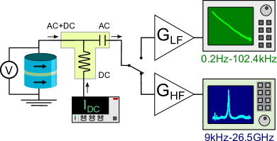
The multilayer MTJ nanopillars have the following structure: IrMn(6.1)/ CoFeB(1.8)/ Ru/ CoFe(2)/ MgO(0.9nm)/ CoFe(0.5)/CoFeB(3.4) where the numbers indicate the thickness of the layers in nm. The pinned layer consists of two FM layers which are antiferromagnetically coupled through a thin ruthenium layer. The lower FM layer is exchange-coupled to an antiferromagnetic IrMn layer. The MgO barrier is deposited by sputtering and the free layer consists of a bi-layer of CoFe/CoFeB. The measured nanopillar devices have elliptical cross-sections of different sizes, with the minor and major axes ranging from 4080 to 65130 (in nm), and a nominal RA product of 1.5 . The easy axis (EA) direction is parallel to the pinned layer’s magnetization coinciding with the major axis of the ellipse, while the in-plane hard axis (HA) is perpendicular (but still in-plane) to the EA. The devices are embedded in impedance matched RF coplanar waveguides for electrical contacting using special RF probes. Figure 1 shows a diagram of the experimental set-up. The samples are biased by a d.c. current which is input through the LF port of a bias tee, and the voltage across the device is measured by a nanovoltmeter. The voltage signal from the sample goes through the mixed port of the bias tee and is input into either LF or HF system through the HF port of the bias tee. The LF system was previously described in Ref. Cascales et al. (2013). Regarding the HF measurement, the voltage fluctuations out of the HF port are amplified by a Miteq AVG6 amplifier, and then input into an Agilent Technologies EXA signal analyzer (bandwidth 9 kHz-26.5 GHz). Details of the calibration of the HF setup may be found in Ref. Cascales (2015).
Previous measurements on devices of this kindHoussameddine et al. (2008, 2009); Houssameddine (2009) have shown that these MTJs fall into two different groups: samples with high resistance and tunneling magnetoresistance (TMR) ratios around 90% (labeled HTMR) and samples with low resistance and TMR ratios around 30-60% (labeled LTMR). The authors report that repetead high-current measurements on HTMR devices may gradually turn them into LTMR devices. These LTMR devices seem to be stable against high-current measurements, and the authors speculate that the difference between sample types could be due to localized reductions in the tunneling barrierHoussameddine et al. (2008). Indeed, the statistics of our MTJs reveal a mean TMR value of around 60% and an average resistance-area (RA) product of 1.8 (in agreement with the nominal value of 1.5 ). MTJs with ultra-low RA are important for practical devices. For junctions with low MgO thicknesses (and low RA products, correspondingly), there exists a correlation between the TMR ratio and the MgO thicknessYuasa et al. (2004). A decrease in TMR is experienced when the thickness of the MgO barrier is reduced, due to local inhomogeneities (or pseudo-pinholes) in the MgO barrier. Obtaining MTJs with low RA products and high TMR ratios, for which homogeneous barriers are needed, is a real engineering challenge. The STT effect requires high current densities, and since MgO barriers only withstand a certain amount of voltage, having a low RA allows high currents to flow through the MTJ without causing the breakdown of the barrierAlvarez-Hérault (2010). We shall focus below on LTMR MTJs, as they are best candidates to study magnetization dynamics and spin torque effects.
Figure 2 shows that when the external field is directed along the easy axis, one observes a step-like transition in resistance, from a high resistance state at positive fields (antiparallel or AP state) to a lower resistance state at negative fields (parallel or P state). In our measurements, positive voltage means that electrons flow from the pinned to the free electrode, promoting the P state. Negative voltage favors the AP state. The high and low frequency noise measurements shown in this work were carried out in the same 40x80nm2 sample, although qualitatively similar results were obtained for several others. Fig. 2(a) shows changes in the coercive field with the applied current, obtained from resistive transitions measured by sweeping the field positive to negative values. A full TMR cycle taken at low bias (2 mV) is shown in the inset of Fig. 2(a). As could be seen in Fig. 2(b), the coercive field is stable for negative currents (the AP state is favored) while shifts to lower values (favoring the P state) for the positive currents. Note that the results obtained from both high and low frequency set-ups have been plotted in Fig. 2(b).
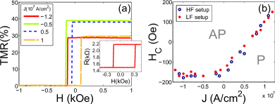
s
A typical high frequency noise spectrum presents resonance peaks centered around a frequency , with linewidths . An example of such a spectrum is shown in Fig. 3(a). We have studied the evolution of these resonance modes with both an external magnetic field and a d.c. current . The resonance peaks may be characterized by their , and output power of the microwave emission. We have constructed surface plots (see Fig. 3(b)) at constant current, with the high frequency spectra taken at different applied external fields, so the evolution of the modes with the current can be detected. For positive currents, the P state is stabilized and the AP state is destabilized, and vice versa for negative currents. This is reflected in the fact that the modes observed have higher amplitudes in the AP state for positive currents, and in the P state for negative currents.
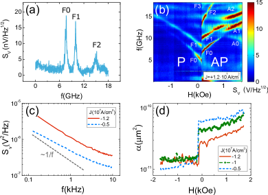
Six clear modes are detected, which come from oscillations of the free layer (labeled F0, F1, …) and the SAF structure (A0, A1 and A3). The free layer modes are V-shaped, while the modes not showing a minimum at low fields correspond to SAF modesHelmer et al. (2010). The SAF modes should present a minimum at the high field required for the spin-flop of the SAF, but our applied fields are not high enough. The F0 mode typically corresponds to excitations localized near the edges of the layerHelmer et al. (2010). The F2 mode only appears in the state which is excited (P or AP), depending on the polarity of the current. A possible fourth free layer mode, F3, is labeled, although it appears very tenuous and is only present for . Several other samples revealed similar oscillation modes. We have carried out an analysis of the F0 and F1 modes (as they have the highest amplitudes) in the manner discussed in Ref.Houssameddine et al. (2008). The analysis of these results reveals that for negative currrents, a decrease in frequency is observed for the first and second modes in the P state, starting at . Under the same conditions, the AP state data presents the same dependence as the P state, but the features are not as clear. The change of the oscillation frequency with respect to the TFMR regime and the linewidth of the F0 and F1 modes for the P state (H=-350 Oe) is shown in Fig. 4(a) and (b). As can be seen, the decrease in frequency of the F0 and F1 modes resembles the transition from T-FMR to SSP reported on similar devices in Ref.Houssameddine et al. (2008). The minimum linewidth obtained for the F0 mode is around 400 MHz, which agrees with what was previously observed for the intermittent steady state in Ref.Houssameddine et al. (2009). The microwave power was found to monotonically increase with the current and is not shown for brevity. Therefore we conclude that our highest negative current takes our sample to an intermittent SSP regimeHoussameddine et al. (2009). For positive currents (not shown) such a transition is not found, and the emitted microwave power and low frequency noise monotonically increase with the applied current.
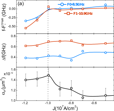
Low frequency noise measurements were also carried out in the same sample, using the same current and magnetic field values. The low frequency spectra (see Fig. 3(c)) may be described by where is the applied voltage, the sample area, is the normalized 1/f noise or Hooge parameter and . The extraction of the 1/f parameters was carried out by carrying out a linear fit to between . The Hooge parameter remains somewhat constant for each magnetic state (P or AP) (see Fig. 3(d). The analysis of the 1/f noise data as a function of the current density reveals the signature of effects observed in the HF results. As is shown in Fig. 4(c), the Hooge parameter in the P state, , monotonically increases with the applied current for current densities substantially below . This trend is observed regardless of the field range within the P state chosen for the average. Then, only for negative currents, the normalized noise reaches a maximum and starts decreasing at around .
1/f noise in spin torque oscillators has been tied to hopping of the oscillation modes, where each random hopping event leads to a jump in the phase of the oscillatorEklund et al. (2014); Sharma et al. (2014). As the current is increased towards the critical value for an intermittent SSPHoussameddine et al. (2009) (, these phase jumps increase in number, which is reflected in 1/f results. When the intermittent SSP is reached and the current continues increasing, the hopping events gradually become less frequent until eventually reaching the purely SSP for a second critical currentHoussameddine et al. (2009) (not reached in our experiment). So by comparing our low frequency results with the high frequency data, we can ascertain that we are detecting signs of spin-torque related phenomena in low frequency 1/f measurements. Further, our low frequency results seem to be more sensible to ST-driven effects than high frequency measurements, since the 1/f noise begins increasing for lower current densities than the ones needed to observe any change in the oscillation modes (TFMR-SSP transition).
We remark that qualitatively different low frequency noise was observed in HTMR junctions with spin torque effects being suppressed in the current range under study. These MTJs, expected to have a more uniform barrier revealed a decrease in the Hooge factor with an increasing applied bias, similarly to what was previously observed for Fe/MgO/Fe MTJs with 2-3 nm thick MgO barriersGokce et al. (2006); Aliev et al. (2007); Almeida et al. (2008).
In summary, current switching effects have been observed in low TMR nanopillar MTJs of sizes under 100nm Houssameddine et al. (2008, 2009); Houssameddine (2009) if the MTJs are biased along the easy axis, where an AP/P switch is favored for positive currents. The analysis of the high frequency oscillation modes with respect to the bias current reveals the onset of a steady-state precession regime for negative currents, when the field is applied along the easy axis. A comparison of this analysis with 1/f noise as a function of the current shows that the changes in magnetization dynamics in the GHz range are reflected in the low frequency noise. The beginning of the transition to the steady state regime appears as a maximum in the normalized 1/f noise (Hooge parameter). The obtained results should help to define the “current window range” for the potential application of nm sized magnetic tunnel junctions by using LF noise measurement techniques.
References
- Julliere (1975) M. Julliere, Physics Letters A 54, 225 (1975).
- Moodera et al. (1995) J. S. Moodera, L. R. Kinder, T. M. Wong, and R. Meservey, Phys. Rev. Lett. 74, 3273 (1995).
- Miyazaki and Tezuka (1995) T. Miyazaki and N. Tezuka, Journal of Magnetism and Magnetic Materials 139, 0 (1995).
- Ralph and Stiles (2008) D. Ralph and M. Stiles, Journal of Magnetism and Magnetic Materials 320, 1190 (2008).
- Slonczewski (1996) J. Slonczewski, Journal of Magnetism and Magnetic Materials 159, 0 (1996).
- Kim et al. (2008) J.-V. Kim, Q. Mistral, C. Chappert, V. S. Tiberkevich, and A. N. Slavin, Phys. Rev. Lett. 100, 167201 (2008).
- Tiberkevich et al. (2007) V. Tiberkevich, A. Slavin, and J.-V. Kim, Applied Physics Letters 91, 192506 (2007).
- Mistral et al. (2006) Q. Mistral, J.-V. Kim, T. Devolder, P. Crozat, C. Chappert, J. A. Katine, M. J. Carey, and K. Ito, Applied Physics Letters 88, 192507 (2006).
- Petit et al. (2007) S. Petit, C. Baraduc, C. Thirion, U. Ebels, Y. Liu, M. Li, P. Wang, and B. Dieny, Phys. Rev. Lett. 98, 077203 (2007).
- Houssameddine et al. (2008) D. Houssameddine, S. H. Florez, J. A. Katine, J.-P. Michel, U. Ebels, D. Mauri, O. Ozatay, B. Delaet, B. Viala, L. Folks, et al., Applied Physics Letters 93, 022505 (2008).
- Houssameddine et al. (2009) D. Houssameddine, U. Ebels, B. Dieny, K. Garello, J.-P. Michel, B. Delaet, B. Viala, M.-C. Cyrille, J. A. Katine, and D. Mauri, Phys. Rev. Lett. 102, 257202 (2009).
- Devolder et al. (2009) T. Devolder, L. Bianchini, J.-V. Kim, P. Crozat, C. Chappert, S. Cornelissen, M. Op de Beeck, and L. Lagae, Journal of Applied Physics 106, 103921 (2009).
- Thadani et al. (2008) K. V. Thadani, G. Finocchio, Z.-P. Li, O. Ozatay, J. C. Sankey, I. N. Krivorotov, Y.-T. Cui, R. A. Buhrman, and D. C. Ralph, Phys. Rev. B 78, 024409 (2008).
- Cascales et al. (2013) J. P. Cascales, D. Herranz, J. L. Sambricio, U. Ebels, J. A. Katine, and F. G. Aliev, Applied Physics Letters 102, 092404 (2013).
- Cascales (2015) J. P. Cascales, Ph.D. thesis, Universidad Autónoma de Madrid, Spain (2015).
- Houssameddine (2009) D. Houssameddine, Theses, Université Joseph-Fourier - Grenoble I (2009).
- Yuasa et al. (2004) S. Yuasa, T. Nagahama, A. Fukushima, Y. Suzuki, and K. Ando, Nature Materials 3, 868 (2004).
- Alvarez-Hérault (2010) J. Alvarez-Hérault, Theses, Université de Grenoble (2010).
- Helmer et al. (2010) A. Helmer, S. Cornelissen, T. Devolder, J.-V. Kim, W. van Roy, L. Lagae, and C. Chappert, Phys. Rev. B 81, 094416 (2010).
- Eklund et al. (2014) A. Eklund, S. Bonetti, S. R. Sani, S. Majid Mohseni, J. Persson, et al., Applied Physics Letters 104, 092405 (2014).
- Sharma et al. (2014) R. Sharma, P. Dürrenfeld, E. Iacocca, O. G. Heinonen, J. Åkerman, and P. K. Muduli, Applied Physics Letters 105, 132404 (2014).
- Gokce et al. (2006) A. Gokce, E. R. Nowak, S. H. Yang, and S. S. P. Parkin, Journal of Applied Physics 99, 08 (2006).
- Aliev et al. (2007) F. G. Aliev, R. Guerrero, D. Herranz, R. Villar, F. Greullet, C. Tiusan, and M. Hehn, Applied Physics Letters 91, 232504 (2007).
- Almeida et al. (2008) J. M. Almeida, P. Wisniowski, and P. Freitas, Magnetics, IEEE Transactions on 44, 2569 (2008).