Localization length of nearly periodic layered metamaterials
Abstract
We have analyzed numerically the localization length of light for nearly periodic arrangements of homogeneous stacks (formed exclusively by right-handed materials) and mixed stacks (with alternating right and left-handed metamaterials). Layers with index of refraction and thickness alternate with layers of index of refraction and thickness . Positional disorder has been considered by shifting randomly the positions of the layer boundaries with respect to periodic values. For homogeneous stacks, we have shown that the localization length is modulated by the corresponding bands and that is enhanced at the center of each allowed band. In the limit of long-wavelengths , the parabolic behavior previously found in purely disordered systems is recovered, whereas for a saturation is reached. In the case of nearly periodic mixed stacks with the condition , instead of bands there is a periodic arrangement of Lorenztian resonances, which again reflects itself in the behavior of the localization length. For wavelengths of several orders of magnitude greater than , the localization length depends linearly on with a slope inversely proportional to the modulus of the reflection amplitude between alternating layers. When the condition is no longer satisfied, the transmission spectrum is very irregular and this considerably affects the localization length.
pacs:
71.55.Jv,78.67.PtI Introduction
During the last decades, a new type of artificial materials, the so-called left-handed metamaterials (LH), have attracted a great deal of attention. They present negative indices of refraction for some wavelengths VESELAGO68 , with considerable applications in modern optics and microelectronics YU04 ; CAL05 ; MAR08 ; SHAL07 . Metamaterials can resolve images beyond the diffraction limit PEN00 ; SMITH04 , act as an electromagnetic cloak PEN06 ; LEO06 ; SCHU06 , enhance the quantum interference YANG08 or yield to slow light propagation PAPA09 .
Regarding the localization length in disordered systems, the presence of negative refraction in one-dimensional (1D) disordered metamaterials strongly suppresses Anderson localization MOGI11(a) . As a consequence, an unusual behavior of the localization length at long-wavelengths has been observed. Asatryan et al. reported a sixth power dependence of with under refractive-index disorder ASA07 ; ASA10(a) instead of the well-known quadratic asymptotic behavior SHENG86 ; SHENG90 ; STER93 ; SHENG95 . Recently, Mogilevtsev et al. MOGI10 have also found a suppression of Anderson localization of light in 1D disordered metamaterials combining oblique incidence and dispersion while Torres-Herrera et al. TORR12 have developed a fourth order perturbation theory to resolve the problem of non-conventional Anderson localization in bilayered periodic-on-average structures. The effects of polarization and oblique incidence on light propagation in disordered metamaterials were also studied in Ref. ASA10(b) .
In this article, we calculate numerically the localization length of light for a one-dimensional arrangement of layers with index of refraction and thickness alternating with layers of index of refraction and thickness . In order to introduce disorder in our system, we change the position of the layer boundaries with respect to the periodic values maintaining the same values of the refraction indices and . This is the case of positional disorder, in contrast to the compositional disorder where there exist fluctuations of the index of refraction TORR11 .
Two structures will be analyzed in detail: homogeneous stacks (H), composed entirely by the traditional right-handed materials (RH) with positive indices of refraction, and mixed stacks (M) with alternating layers of left- and right- handed materials. For the sake of simplicity, the optical path in both layers will be the same, that is, the condition is satisfied in most of the work. These periodic-on-average bilayered photonic systems have already been studied analytically by Izrailev et al. IZRA09 ; IZRA12 . These authors have developed a perturbative theory up to second order in the disorder to derive an analytical expression for the localization length for both H and M stacks. In our case, we have obtained two equations for the localization length as a function of the wavelength from our numerical results. For H stacks, a quadratic dependence of for long-wavelengths is found, as previously reported in the literature. On the other hand, the localization length saturates for lower values of . An exhaustive study of in the allowed and forbidden bands (gaps) of weakly disordered systems will be carried out. We will show that the localization length is modulated by the corresponding bands and this modulation decreases as the disorder increases. For low-disordered M stacks and wavelengths of several orders of magnitude greater than the grating period , the localization length depends linearly on with a slope inversely proportional to the modulus of the reflection amplitude between alternating layers.
The plan of the work is as follows. In Sec. II we carry out an exhaustive description of our one-dimensional disordered system and the numerical method used in our localization length calculations. A detailed analysis of in the allowed bands and gaps of homogeneous stacks is performed in Sec. III where a practical expression for the localization length as a function of and the disorder is derived. In Sec. IV we calculate for mixed stacks of alternating LH and RH layers. A linear dependence of the localization length at long-wavelengths is found for low-disordered M stacks. Finally, we summarize our results in Sec. V.
II System description and numerical model
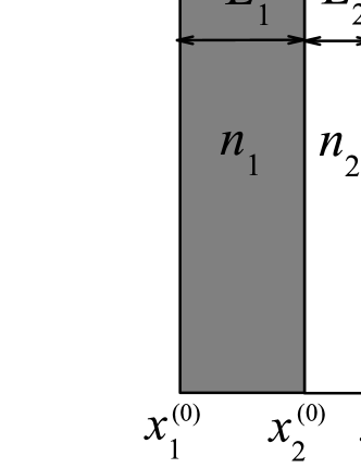
Let us consider a one-dimensional arrangement of layers with index of refraction alternating with layers of index of refraction . The width of each one is the sum of a fixed length for and a random contribution of zero mean and a given amplitude. The wave-numbers in layers of both types are , where is the frequency and the vacuum speed of light. As previously mentioned, the grating period of our system is defined as the sum of the average thicknesses and of the two types of layers, that is, . We have introduced the optical path condition for simplicity (in the case of left-handed layers , so the absolute value has been written to consider these type of materials). Without disorder, each layer would be limited by two boundaries and where is the total number of boundaries. The periodic part of the system considered is schematically represented in Fig. 1.
In the presence of disorder, the position of the corresponding boundaries are
| (1) |
except for the first and the last boundary, so as to maintain the same total length . The parameters are zero-mean independent random numbers within the interval . Throughout all our calculations, we have chosen values of the disorder parameter less than and .
For each , we calculate the transmission coefficient of our structure and average its logarithm, , over 800 disorder configurations. Then, we obtain numerically the localization length via a linear regression of TORR11
| (2) |
Here, the angular brackets stand for averaging over the disorder. We choose 6 values of the total length to perform the linear regression of Eq. (2). The localization length is evaluated as a function of the disorder parameter and the frequency of the incident photon .
We calculate the transmission coefficient of our system via the characteristic determinant method, firstly introduced by Aronov et al. AG91 . This is an exact and non perturbative method that provides the information contained in the Green function of the whole system. In our case, the characteristic determinant can be written as AG91
| (3) |
where the index runs from 1 to and the coefficients and can be written as
| (4) |
and
| (5) |
The parameters , which are the reflection amplitudes between media and , are given by
| (6) |
where corresponds to the impedance of layer and can be be expressed for normal incidence in terms of its dielectric permittivity and magnetic permeability
| (7) |
The quantity entering Eqs. (4) and (5) is a phase term AG91
| (8) |
Here is the wave-number in a layer with boundaries and . This recurrence relation facilitates the numerical computation of the determinant. The initial conditions are the following
| (9) |
The transmission coefficient of our structure is given in terms of the determinant by
| (10) |
III Localization length for homogeneous stacks
Before dealing with mixed stacks, we present results for low-disordered homogeneous systems with underlying periodicity, which has not been previously studied. In this section we perform a detailed analysis of the localization length in the allowed bands and in the forbidden gaps of disordered H stacks as a function of the disorder , the incident wavelength and the reflection coefficient between alternating layers .
As it is well known, in the absence of disorder the transmission spectrum of right-handed systems presents allowed and forbidden bands whose position can be easily determined via the following dispersion relation obtained from the Bloch-Floquet theorem YAR84
| (11) | |||||
where is the Block wave-vector. When the modulus of the right-hand side of Eq. (11) is greater than 1, has to be taken as imaginary. This situation corresponds to a forbidden band. Taking into account the condition , Eq. (11) reduces to
| (12) |
On the other hand, when is equal to unity, the incident frequency is located at the center of the -th allowed band, . After some algebra, we obtain from Eq. (12)
| (13) |
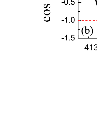
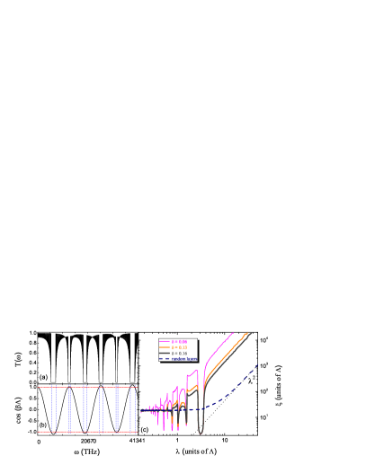
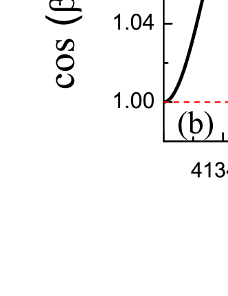
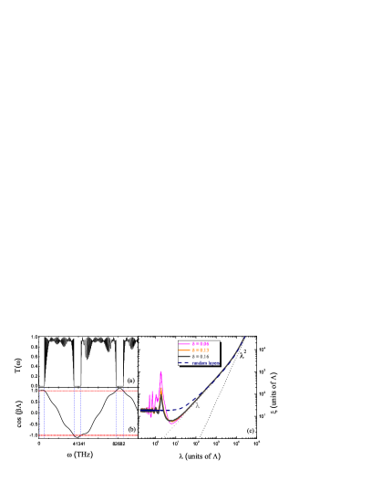
Let us first consider a periodic H stack formed by 50 layers of length 52.92 nm and index of refraction 1.58 alternating with 49 layers of length 39.38 nm and 2.12. The total size of our structure is 4.57 m and the reflection coefficient between alternating layers 0.05259. Fig. 2(a) represents the transmission coefficient as a function of the frequency to illustrate its behavior. Also shown are the center of each allowed band calculated via Eq. (13). There are 99 peaks in each band so they can hardly been resolved on the scale used. Moreover, in Fig. 2(b) the parameter is plotted versus the frequency for this periodic system. The first gap and the first allowed band have been shown for a better comprehension.
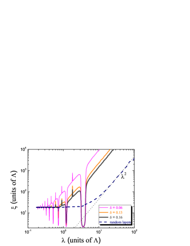
A systematic numerical simulation of a realistic system with 50000 layers has been carried out. The parameters are the same as in the previous example. In Fig. 3 we represent the localization length versus the wavelength for different values of the disorder parameter (shown in the legend of the figure). The dashed line corresponds to ”total disorder”, that is, an arrangement of layers with random boundaries and alternating indices of refraction and . Several features are evident in the figure. For long-wavelengths, one observes a quadratic asymptotic behavior, as can be compared with the dotted line SHENG86 ; SHENG90 ; STER93 ; SHENG95 . An in-deep numerical analysis of the coefficient characterizing this dependence has been performed. To this aim, 20 different H stacks were considered and the following expression for the localization length was found
| (14) |
where is the optical path across one grating period . All the lengths in Eq. (14) are expressed in units of . In the opposite limit of short , the localization length saturates to a constant value ASA10(a) ; BALU85 . Our numerical results have shown that this constant is proportional to the inverse of the reflection coefficient between alternating layers , that is,
| (15) |
Izrailev et al. IZRA09 ; IZRA12 have developed a perturbative theory up to second order in the disorder to calculate analytically the localization length in both homogeneous and mixed stacks. This model is quite general and is valid for both quarter stack medium (mainly considered in our work) and systems with different optical widths. Assuming uncorrelated disorder and random perturbations with the same amplitude in both layers (the main considerations in our numerical calculations) one can easily derive the following analytical expression for at long-wavelengths from Izrailev’s formulation
| (16) |
For similar values of the layer impedances , the first term in Eq. (16) can be approximated by and , so Eq. (16) reduces to
| (17) |
which is similar to our numerical expression Eq. (14).
The randomness only affects partially the periodicity of the system, which manifests in the existence of bands and gaps. The localization length depends on the position in the band and on the disorder. The modulation of by the bands can be clearly appreciated in Fig. 3. These results are consistent with other published works on this topic MOGI11(b) ; LUNA09 . Recently, Mogilevtsev et al. MOGI11(b) have reported that the photonic gaps of the corresponding periodic structure are not completely destroyed by the presence of disorder while Luna-Acosta et al. LUNA09 have shown that the resonance bands survive even for relatively strong disorder and large number of cells.
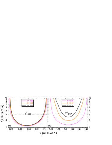
Having a close look into the first gap in Fig. 3, one observes that the localization length is practically independent of the disorder . In order to visualize this effect, Fig. 4 represents (a) the first and (b) the second gaps depicted in Fig. 3. As mentioned, the dependence of with the disorder is almost negligible in the first gap. When the wavelength is similar to the grating period , the influence of the disorder is greater, as can be easily deduced from simple inspection of Fig. 4(b).
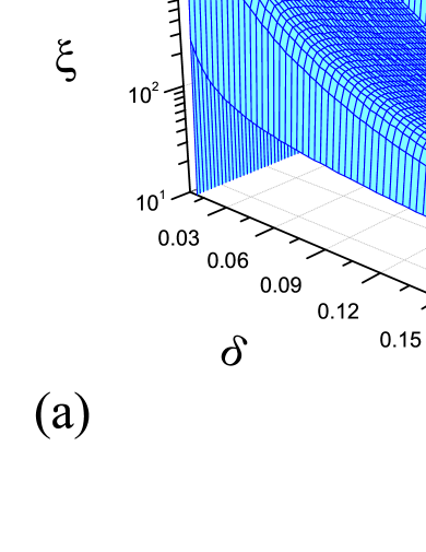
Let us now focus on the allowed bands and study in detail the behavior of the localization length in these regions. To this aim, three-dimensional (3D) graphs of versus the wavelength and the disorder have been plotted in Fig. 5 for (a) the first and (b) the third allowed bands (see again Fig. 2). All this magnitudes have been normalized to the grating period . The localization length is enhanced in a small region around the center of each allowed band. A similar result was found by Hernández-Herrejón et al. HERN10 who obtained a resonant effect of close to the band center in the Kronig-Penney model with weak compositional and positional disorder. This increase in the localization length is due to emergence of the Fabry–Perot resonances associated with multiple reflections inside the layers from the interfaces IZRA09 ; IZRA12 ; IZRA10 . In particular, for homogeneous quarter stack systems, the Fabry–Perot resonances arise exactly in the middle of each allowed band where vanishes IZRA09 ; IZRA12 . The saturation of for short-wavelengths is also appreciated in these 3D images.
Up to now, H stacks with the same optical path in layers of both types have been considered, that is, arrangements verifying the condition in the absence of disorder. As a consequence, the transmission spectrum of the corresponding periodic system presented a symmetric distribution of allowed bands and gaps (as previously shown in Fig. 2). What happens in the case of a non-symmetric band distribution, that is, when the condition is not satisfied? To answer this question, we have plotted the transmission coefficient (Fig. 6(a)) and the parameter (Fig. 6(b)) versus the frequency for a periodic H stack formed by 50 layers of length 52.92 nm and index of refraction 1.58 alternating with 49 layers of length 28.80 nm and 2.12. Note that the condition is no longer held, so the band structure is asymmetric. Accordingly, the localization length shown in Fig. 6(c) presents an irregular form in the allowed and forbidden bands. As in the symmetric case, no band modulation exists for high disorders and the quadratic asymptotic behavior for long-wavelengths is also verified. Moreover, the peaks in the localization length due to Fabry–Perot resonances still can be appreciated, although they are no longer in the center of the bands IZRA09 ; IZRA12 . A total number of 50000 layers was considered in our localization length calculations.
IV Localization length for mixed stacks
Once analyzed in detail the behavior of the localization length for homogeneous systems, let us now deal with M stacks composed of alternating LH and RH layers.
In our numerical calculations we have considered a periodic M stack formed by 50 layers of length 52.92 nm and index of refraction -1.58 alternating with 49 layers of length 39.38 nm and 2.12. Again, the condition has been imposed. Note that this arrangement has similar parameters than the one depicted in Sec. III, but now is negative. This change of sign results in a severe modification of the transmission coefficient , as we will show immediately. For this the periodic system, Fig. 7 represents (a) the transmission coefficient and (b) the parameter versus the frequency of the incident light. Unlike the H stack case, no allowed bands exist and practically the entire transmission spectrum is formed by gaps. A set of periodically distributed Lorentzian resonances is found instead. The position of the center of each resonance is given by Eq. (13), that is, the center of the allowed bands in homogeneous systems.
In respect to the localization length, positional disorder was introduced as explained in Sec. II. As previously considered, the total number of layers in our numerical calculations was 50000 and the number of disordered configurations to average the logarithm of the transmission coefficient was 800. The result is shown in Fig. 8 where the localization length is represented versus the wavelength for different values of the disorder parameter . The dashed line corresponds to the ”total disorder” case. Again, for long-wavelengths a quadratic asymptotic behavior of is found, but now a region where the localization length is proportional to exists. We will turn to this point in the next figure to quantify the slope of this linear dependence. As it is noticed, the Lorentzian resonances associated with multiple reflections in the layers modulate the shape of and this modulation decreases as the disorder increases. Moreover, the saturation of the localization length for low-wavelengths can also be appreciated. As in the H stack case, the constant where saturates is proportional to the inverse of the reflection coefficient between alternating layers .
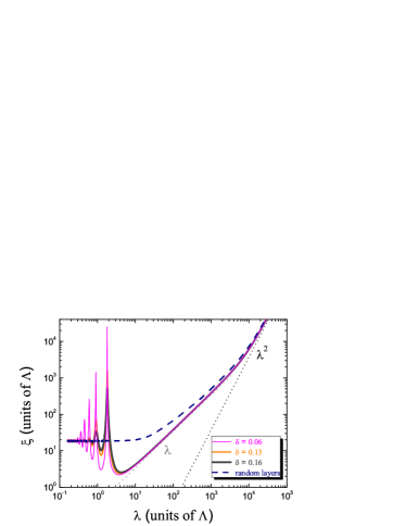
The linear dependence of with the wavelength has been exhaustively studied by our group to find a simple analytical expression for the localization length in this region. More than 30 different M stacks have been simulated and we have arrived at the following empirical equation
| (18) |
where , and are expressed in units of the grating period . In Fig. 9, our numerical calculations of the slope versus have been plotted for several values of , triangles (1.25), squares (3.25) and circles (7.55). The solid lines correspond to the results obtained via Eq. (18). One notices a good degree of validity for a wide range of values.

Finally, let us now consider an asymmetrical M stack where the condition is no longer satisfied. In Fig. 10 we have represented (a) the transmission coefficient and (b) the parameter versus the frequency for a periodic M stack formed by 50 layers of length of length 52.92 nm and index of refraction -1.58 alternating with 49 layers of length 28.80 nm and 2.12. Note the strong difference between this transmission spectrum and the symmetrical one (see Fig. 7(a)) where a set of periodically distributed Lorenztian resonances exists. Despite this fact, the localization length shown in Fig. 10(c) presents a region of linear dependence with the wavelength, as in the symmetric case. However, Eq. (18) cannot be used to evaluate the localization length in this region.
V Discussion and Conclusions
We have analyzed numerically the localization length of light for homogeneous and mixed stacks of layers with index of refraction and thickness alternating with layers of index of refraction and thickness . The positions of the layer boundaries have been randomly shifted with respect to ordered periodic values. The refraction indices and present no disorder.
For H stacks, the parabolic behavior of the localization length in the limit of long-wavelengths, previously found in purely disordered systems SHENG86 ; SHENG90 ; STER93 ; SHENG95 , has been recovered. On the other hand, the localization length saturates for very low values of . The transmission bands modulate the localization length and this modulation decreases with increasing disorder. Moreover, the localization length is practically independent of the disorder at the first gap, that is, it has a very low tendency in this region. We have also characterized in terms of the reflection coefficient of alternating layers and the optical path across one grating period . Eq. (14) has been proved to be valid for a wide range of values, that is, from transparent to opaque H stacks. It has also been shown (see Fig. 5) that the localization length is enhanced at the center of each allowed band.
When left-handed metamaterials are introduced in our system, the localization length behavior presents some differences with respect to the traditional stacks, formed exclusively by right-handed materials. For low-disordered M stacks and wavelengths of several orders of magnitude greater than the grating period , the localization length depends linearly on with a slope inversely proportional to the modulus of the reflection amplitude between alternating layers (see Eq. (18)). As in the H case, saturates for low-wavelengths, being this saturation constant proportional to the inverse of .
If we take into account losses, there is an absorption term whose absorption length is ASA10(a)
| (19) |
where is an absorption coefficient. The inverse of the total decay length is the sum of the inverse of the localization length plus the inverse of the absorption length . Note that is proportional to , so, for low-disordered M stacks and weak absorption metamaterials, the final expression for the localization length in the linear region can be written as
| (20) |
In the case of both homogeneous and mixed stacks with non-symmetric band distribution, that is, when the condition is not satisfied, the localization length presents an irregular form in all the transmission spectrum. These changes in are more sensitives in mixed stacks than in homogeneous structures.
Acknowledgements.
The authors would like to acknowledge Vladimir Gasparian for many interesting discussions. M.O. would like to acknowledge financial support from the Spanish DGI, project FIS2009-13483.References
- (1) V. G. Veselago, Sov. Phys. Usp. 102, 509 (1968).
- (2) K. Yu. Bliokh and Yu. P. Bliokh, Phys. Usp. 47, 393 (2004).
- (3) C. Caloz and T. Ito, Proc. IEEE 93, 1744 (2005).
- (4) V. M. Shalaev, Nat. Photonics 1, 41 (2007).
- (5) P. Marcos and C. M. Soukoulis, Wave Propagation from Electrons to Photonic Crystals and Left-Handed Materials (Pricenton University Press, Pricenton, 2008).
- (6) J. B. Pendry, Phys. Rev. Lett. 85, 3966 (2000).
- (7) D. R. Smith, J. B. Pendry and M. C. K.Wiltshire, Science 305, 788 (2004).
- (8) J. B. Pendry, D. Shurig and D. R. Smith, Science 312, 1780 (2006).
- (9) U. Leonhardt, Science 312, 1777 (2006).
- (10) D. Schurig, J. Mock, B. Justice, S. Cummer, J. Pendry, A. Starr and D. Smith, Science 314, 977 (2006).
- (11) Y. Yang, J. Xu, H. Chen and S. Zhu, Phys. Rev. Lett. 100, 043601 (2008).
- (12) N. Papasimakis and N. Zheludev, Opt. Photonics News 20, 22 (2009).
- (13) D. Mogilevtsev, F. A. Pinheiro, R. R. dos Santos, S. B. Cavalcanti and L. E. Oliveira, Phys. Rev. B 84, 094204 (2011).
- (14) A. A. Asatryan, L. C. Botten, M. A. Byrne, V. D. Freilikher, S. A. Gredeskul, I. V. Shadrivov, R. C. McPhedran and Y. S. Kivshar, Phys. Rev. Lett. 99, 193902 (2007).
- (15) A. A. Asatryan, S. A. Gredeskul, L. C. Botten, M. A. Byrne, V. D. Freilikher, I. V. Shadrivov, R. C. McPhedran and Y. S. Kivshar, Phys. Rev. B 81, 075124 (2010).
- (16) P. Sheng, B. White, Z.-Q. Zhang and G. Papanicolaou, Phys. Rev. B 34, 4757 (1986).
- (17) P. Sheng, B. White, Z.-Q. Zhang and G. Papanicolaou, Scattering and Localization of Classical Waves in Random Media (World Scientific, Singapore, 1990).
- (18) C. Martijn de Sterke and R. C. McPhedran, Phys. Rev. B 47, 7780 (1993).
- (19) P. Sheng, Introduction to Wave Scattering, Localization, and Mesoscopic Phenomena (Academic, New York, 1995).
- (20) D. Mogilevtsev, F. A. Pinheiro, R. R. dos Santos, S. B. Cavalcanti and L. E. Oliveira, Phys. Rev. B 82, 081105(R) (2010).
- (21) E. J. Torres-Herrera, F. M. Izrailev and N. M. Makarov, Europhys. Lett. 98, 27003 (2012).
- (22) A. A. Asatryan, L. C. Botten, M. A. Byrne, V. D. Freilikher, S. A. Gredeskul, I. V. Shadrivov, R. C. McPhedran and Y. S. Kivshar, Phys. Rev. B 82, 205124 (2010).
- (23) E. J. Torres-Herrera, F. M. Izrailev and N. M. Makarov, Low Temp. Phys. 37, 957 (2011).
- (24) F. M. Izrailev and N. M. Makarov, Phys. Rev. Lett. 102, 203901 (2009).
- (25) F. M. Izrailev, A. A. Krokhin and N. M. Makarov, Phys. Rep. 512, 125 (2012).
- (26) A. G. Aronov, V. Gasparian and U. Gummich, J. Phys.: Condens. Matter 3, 3023 (1991); V. Gasparian, M. Ortuño, J. Ruiz, E. Cuevas and M. Pollak, Phys. Rev. B 51, 6743–6746 (1995).
- (27) A. Yariv and P. Yeh, Optical Waves in Crystals, Propagation and Control of Laser Radiation (Wiley, New York, 1984); O. del Barco, M. Ortuño and V. Gasparian, Phys. Rev. A 74, 032104 (2006); O. del Barco and M. Ortuño, Phys. Rev. A 81, 023833 (2010).
- (28) V. Baluni and J. Willemsen, Phys. Rev. A 31, 3358 (1985).
- (29) D. Mogilevtsev, F. A. Pinheiro, R. R. dos Santos, S. B. Cavalcanti and L. E. Oliveira, Phys. Rev. B 84, 094204 (2011).
- (30) G. A. Luna-Acosta, F. M. Izrailev, N. M. Makarov, U. Kuhl and H.-J. Stöckmann, Phys. Rev. B 80, 115112 (2009).
- (31) J. C. Hernández-Herrejón, F. M. Izrailev and L. Tessieri, J. Phys. A: Math. Theor. 43, 425004 (2010).
- (32) F. M. Izrailev, N. M. Makarov and E. J. Torres-Herrera, Physica B: Condens. Matt. 405, 3022 (2010).