Analysis of transition between different ringing schemes of the church bell
Abstract
In this paper we investigate dynamics of church bells, characterize their most common working regimes and investigate how to obtain them. To simulate the behavior of the yoke-bell-clapper system we use experimentally validated hybrid dynamical model developed basing on the detailed measurements of the biggest bell in the Cathedral Basilica of St Stanislaus Kostka, Lodz, Poland. We introduce two parameters that describes the yoke design and the propulsion mechanism and analyze their influence on the systems’ dynamics. We develop two-parameter diagrams that allow to asses conditions that ensures proper and smooth operation of the bell. Similar charts can be calculated for any existing or non-existing bell and used when designing its mounting and propulsion. Moreover, we propose simple and universal launching procedure that allows to decrease the time that is needed to reach given attractor. Presented results are robust and indicate methods to increase the chance that the instrument will operate properly and reliably regardless of changes in working conditions.
keywords:
Bells , dynamics , impacting system , hybrid system , ringing schemes1 Introduction
Bells are one of the oldest musical instruments which still play an important cultural role. They were invented in China but today their sound announces major events all around the world. Depending on the region bells are mounted in a number of different ways basing on local customs and tradition. In Europe we can encounter three characteristic mounting layouts: Central European, English and Spanish. In Central Europe bells usually tilt on their axis with maximum amplitude of oscillations below degrees. In the English system the amplitude of oscillations is greater and bells perform nearly a complete rotations in both directions. Conversely, in the Spanish system bells rotate continuously in the same direction. All these mounting layouts were developed throughout centuries basing on experience and intuition of bell-founders and craftsmen. It is common that the bells are cast using casting mould passed down for ages from father to son and so forth. Although the design of a bell, its yoke, clapper and a belfry has been being improved for ages, proper modeling of their dynamics is still a challenging task.
The dynamics a yoke-bell-clapper system is extremely complex and difficult to analyze due to nonlinear characteristic, repetitive impacts and complicated excitation. Moreover, depending on the mounting layout different dynamical states can be observed and each type of yoke has its own specific properties. However, already in 19th century Wilhelm Veltmann tried to describe mathematically the behavior of the famous Emperor’s bell in the Cologne Cathedral [17, 18]. He used simplified equations of motion and explained why the clapper always remained on the middle axis of the bell instead of striking its shell. His model was developed basing on the equations of a double physical pendulum. Heyman and Threlfrall [5] use similar model to estimate inertia forces induced by a swinging bell. The knowledge of loads induced by ringing bells is crucial during the design and restoration processes of belfries. That is why there is a number of works considering dynamic interactions between bell towers and bells mounted in different manners. Muller [12], Steiner [16] and Schutz [14] focus on Central European mounting system which is also considered in the German DIN standard [1]. We can find similar studies concerning the Spanish system [2, 3] and the English system [6, 7]. Ivorra et. al. present the comparison between the three mounting layouts and prove that in the Spanish system forces transmitted to the supporting structure are significantly lower than in the other two. Results presented in [4, 10] show that in many cases we can improve bells’ working conditions slightly modifying the yoke or its support.
Apart from the studies concerning interactions between bells and their supports there is a number of publications focusing on the dynamics of the instrument itself or the clapper to the bell collisions. Klemenc et. al. contributed with a series of papers [8, 9] devoted to the analysis of the clapper-to-bell impacts. Authors investigate the consequences of the repetitive hits and compare experimental data with numerical results obtained from the finite-element model. Presented results prove that full-scale finite-element model is able to reproduce the effect of collisions but requires long computational times and complex, detailed models. Therefore, it would be difficult to use such models to analyze the dynamics of bells. Because of that, recently we observe the tendency to use hybrid dynamical models which are much simpler and give accurate results with less modeling and computational effort. In [11] authors propose lumped parameter model of the bells mounted in Central European system and prove that with the model we are able to predict impact acceleration and bell’s period of motion.
In our previous publication [13] we present an improved hybrid dynamical model of the yoke-bell-clapper system. All parameter values involved in the model have been determined basing on the measurements of the biggest bell in the Cathedral Basilica of St Stanislaus Kostka, Lodz, Poland. Proposed model is validated by comparing the results of numerical simulations with experimental data. The presented results show that the introduced model is a reliable predictive tool and can be used for further case studies
In this paper we describe the most common working regimes of bells and investigate how the yoke design and the propulsion mechanism influence their dynamics. To simulate the behavior of the yoke-bell-clapper system we use the hybrid dynamical model that we present in detail in our previous publication [13]. We characterize the solutions that can be considered as the proper operation of the bell and analyze how the geometry of the yoke and the driving motor output affect the dynamics of the system. We introduce two influencing parameters and develop diagrams that allow to asses how the bell’s behavior depends on the yoke type and propulsion amplitude. Such plots describe how presumed working regimes can be obtained and can be beneficial during the design and/or restoration processes of the bells. In addition, we investigate the time that is needed to reach given attractor. Presented results prove that in some cases special launching procedure of the instrument should be introduced to shorten the time of transient motion. Finally, we propose simple and universal control of the driving mechanism that allows to decrease transient time significantly.
The paper is organized as follows. In Section 2 we describe the hybrid dynamical model of the church bell and introduce parameters that influence the system’s dynamics. In Section 3 we characterize the 7 most common working regimes and in Section 4 investigate how they can be obtained. Finally, in Section 5 the conclusions are drawn.
2 Model of the system
The hybrid dynamical model of the yoke-bell-clapper system that we consider in this paper has been described in detail in our previous publication [13]. To develop the model and determine its parameters values we have performed detailed measurements of the existing bell named “The Heart of Lodz” (the biggest bell in the Cathedral Basilica of St Stanislaus Kostka in Lodz). Using the same bell we have tuned and validated the model by comparing the results of numerical simulations with the data collected during a series of experiments. Presented results show that the model is a reliable predictive tool which can be used to simulate the behavior of a wide range of yoke-bell-clapper systems. In next subsections we briefly describe the derivation of the equations of motion and present the influencing parameters.
2.1 Geometry of the yoke-bell-clapper system
The model that we use is build up based on the analogy between freely swinging bell and the motion of the equivalent double physical pendulum. The first pendulum has fixed axis of rotation and models the yoke together with the bell that is mounted on it. The second pendulum is attached to the first one and imitates the clapper. The photo of the bell that has been measured to obtain the parameters values is presented in Fig.2.1 (a). In Figs.2.1 (b,c) we show schematic model of the bell indicating the position of the rotation axes of the bell , the clapper and presenting parameters involved in the model. For simplicity, henceforth, we use term “bell” with respect to the combination of the bell and it’s yoke which we treat as one solid element.
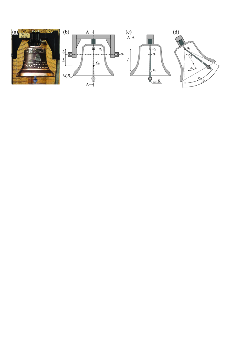
The model involves eight physical parameters. Parameter describes the distance between the rotation axis of the bell and its center of gravity (point ), is the distance between the rotation axis of the clapper and its center of gravity (point ). The distance between the bell’s and the clapper’s axes of rotation is given by parameter . The mass of the bell is described by parameter , while parameter characterizes the bell’s moment of inertia referred to its axis of rotation. Similarly, parameter describes the mass of the clapper and stands for the clapper’s moment of inertia referred to its axis of rotation.
Considered model has two degrees of freedom. In Fig. 2.1 (d) we present two generalized coordinates that we use to describe the state of the system: the angle between the bell’s axis and the downward vertical is given by and the angle between the clapper’s axis and downward vertical by . Parameter (see 2.1 (d)) is used to describe the clapper to the bell impact condition which is as follows:
| (2.1) |
Synonymously, collision between the bell and the clapper occurs when the absolute difference between the bell’s and the clapper’s angular displacements is equal to .
2.2 Equations of motion - modeling of an oscillatory motion of the system
In this section we present the mathematical model that we use to simulate oscillatory motion of the investigated yoke-bell-clapper system. We use Lagrange equations of the second type and derive two coupled second order ODEs that describe the motion of the considered system (full derivation can be found in [13]):
| (2.2) |
| (2.3) |
where stands for gravity and describes the effects of the linear motor propulsion. The motor is active - and excites the bell - when its deflection from vertical position is smaller than . The generalized momentum generated by the motor is given by the piecewise formula:
| (2.4) |
where is the maximum achieved torque. Although, the above expression is not an accurate description of the effects generated by the linear motor, in [13] we prove that it is able to reproduce the characteristics of the modern bells’ propulsions.
There are eleven parameters involved in the mathematical model presented above. The parameters have the following values: , , , , , , and , , , . As aforementioned, all parameters values have been evaluated specifically for the purpose. For integration of the model described above we use the fourth-order Runge–Kutta method. ODEs 2.2 and 2.3 together with the discreet model of impact described in the next Subsection create a hybrid dynamical system.
2.3 Modeling of the clapper to the bell impact
After considering free motion conditions, in this Section we briefly refer to the discreet impact model which is was proposed by Meneghetti and Rossi [11] and validated experimentaly in our previous publication [13]. When the condition 2.1 is fulfilled we stop the integration process. Then, instead of analyzing the collision course, we restart simulation updating the initial conditions of equations 2.2 and 2.3 by switching the bell’s and the clapper’s angular velocities from the values before the impact to the ones after the impact. The angular velocities after the impact are obtained taking into account the energy dissipation and the conservation of the system’s angular momentum that are expressed by the following formulas:
| (2.5) |
| (2.6) |
where index stands for “after impact”, index for “before impact” and parameter is the coefficient of energy restitution. In our simulations we assume referring to a series of experiments performed by Rupp et. al. [15]. In our previous investigation [13] we have analyzed influence of on the response of system and we have proved that dynamics of the system barely changes for small alterations of parameter (). Hence, we claim that there is no need to further adjust the value of for the considered bell.
2.4 Influencing parameters
The mathematical model of the ringing bell described in Section 2 contains 12 parameters (, , , , , , , , , , , ) but most of them are self dependent. Moreover, we have to remember that we consider a musical instrument, hence we cannot change some of its features as it could affect the sound it generates. In real applications we can easily modify the driving motor and the mounting of the bell (by changing the design of the yoke). Therefore, we try to describe how changes of the propulsion and the yoke’s design influence the system’s dynamics. As a reference, we use values of parameters characteristic for “The Heart of Lodz” and alter them to simulate the changes in the propulsion or mounting layout.
In our investigation we assume the linear motor propulsion that is described by piecewise function given by the formula 2.4. Hence, we can modify the effects generated by the motor by changing the range of bell’s deflection in which the motor is active (in our case ) or by altering the maximum generated torque . Practically, it is much easier to modify the maximal momentum which can be realized either by replacing the motor or by changing the length of the torque arm. Therefore, we take as the parameter that describes the driving motor characteristic and use it as the first controlling parameter.
To describe the modifications of the yoke we introduce new parameter and take it as the second influencing parameter. In Fig. 2.2 we explain the meaning of parameter.
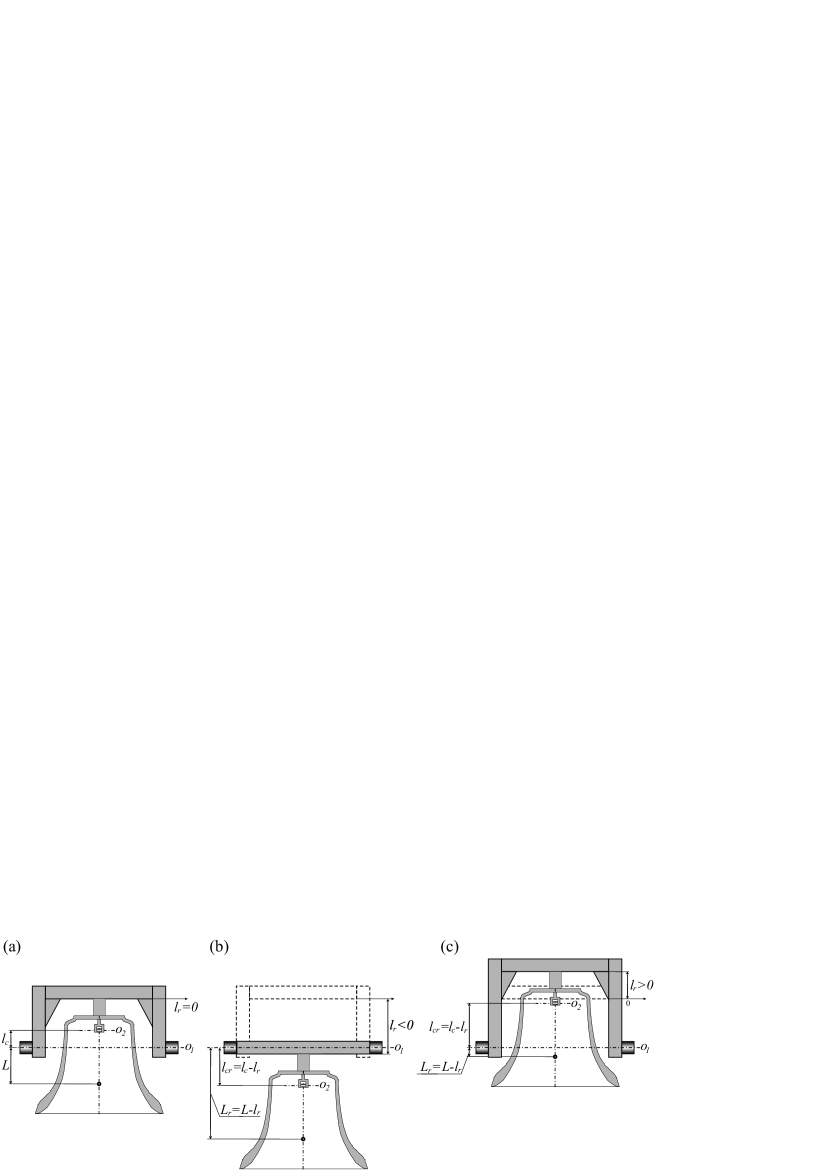
For the reference yoke (“The Heart of Lodz” yoke) we assume . If we change the yoke design so that the bell’s center of gravity is lowered, then and as the value of we take the distance by which the bell’s center of gravity is shifted with respect to the reference yoke. Similarly, if the bell’s center of gravity is elevated, we assume and take its displacement as the value of . As a maximum considered value of we take because for rotation axis of the bell goes through its center of mass.
It is important to point out that changes of value affect other parameters of the model. Hence, whenever we change the value of we have to swap three parameters: has to be replaced by , must be replaced by , and finally by . Values of , and are calculated using the following formulas:
| (2.7) |
3 Different working regimes of the bell
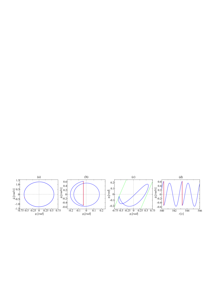
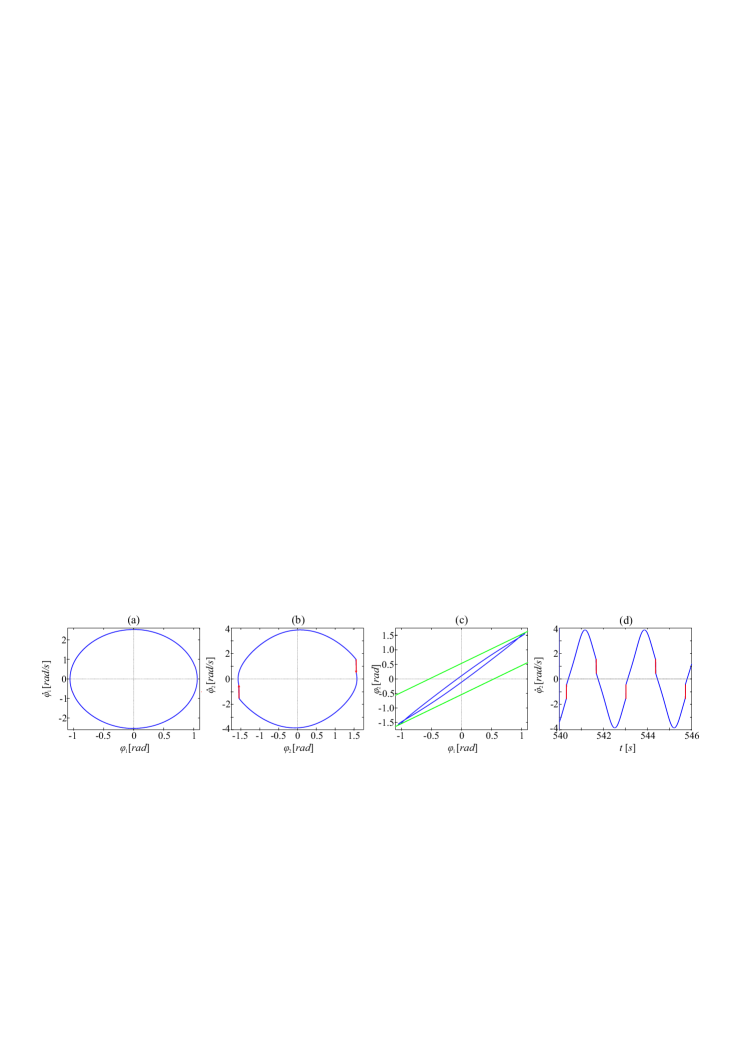
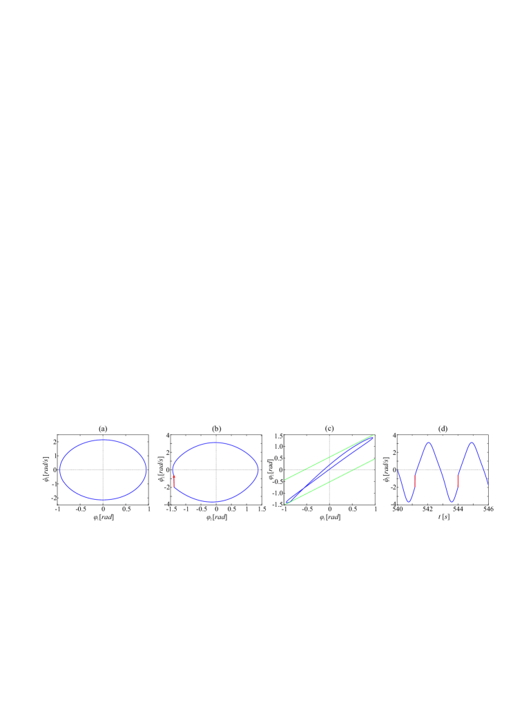
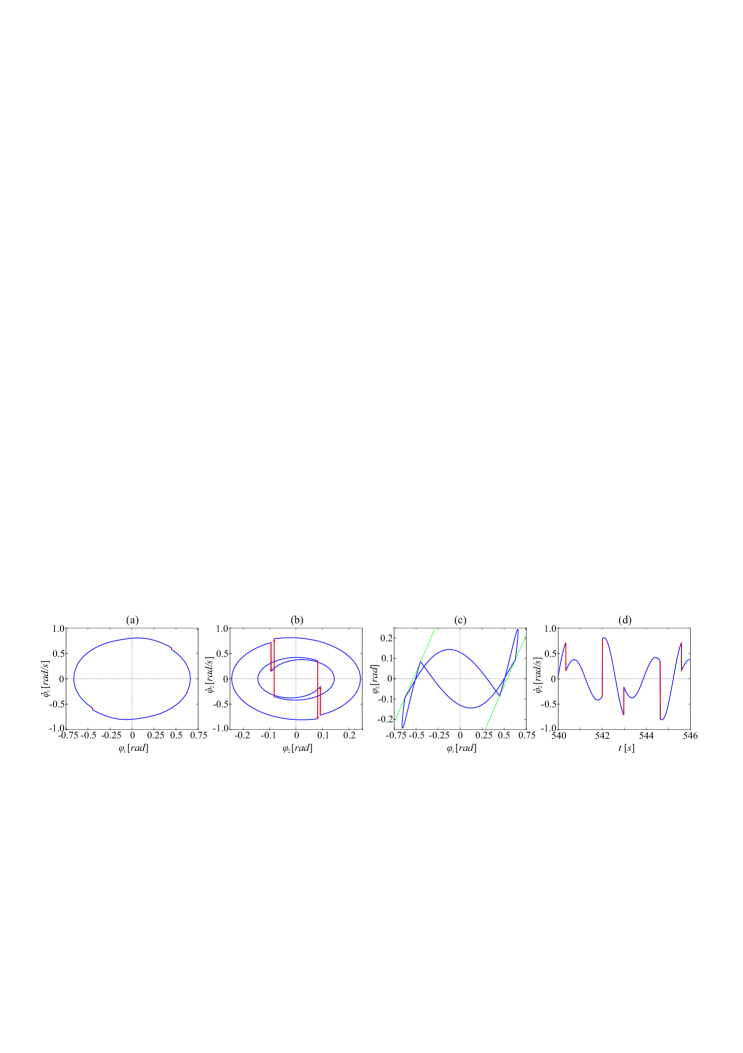
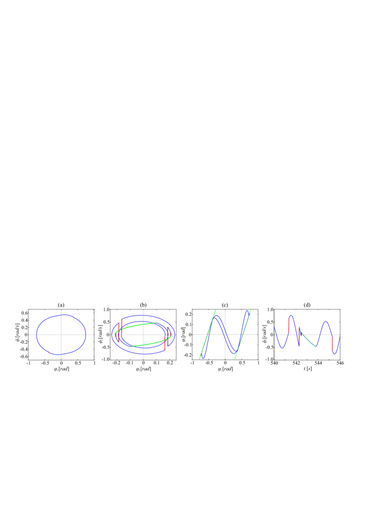
The considered system is not only hybrid and nonlinear but also piecewise due to the model of driving linear motor. Hence it can exhibit a plethora of different dynamical phenomena such as periodic, quasi periodic and chaotic attractors with different number of collisions. Therefore, a particular bell can behave quite differently depending on the yoke design and the driving technique. Still, only few types of periodic attractors can be considered as a proper working regimes and have practical applications. These regimes are often called ringing schemes and can be classified in groups that have common characteristics. The features that are important during the categorization are principally: the period between the consecutive impacts, the number of collisions during one period of motion and the course of the collisions. In this section we point out and describe the seven most commonly meet types of behavior. We use four types of plots to present considered working regimes: phase portraits of the bell and the clapper, trajectory projected in the section of phase space showing relation between the angular position of the bell and the clapper and time trace of the clapper’s velocity. We use blue lines to present attractors and trajectories; red lines and arrows are used to present changes of velocity that are the effects of collisions while green lines are plots of the impact condition 2.1 and indicate when the collisions occur.
3.1 Falling clapper
We say that the bell works in a “falling clapper” manner if the collisions between the bell and the clapper occur when they perform an anti-phase motion. This type of behavior is common for bells that are mounted in the European manner and “The Heart of Lodz” is an example of a bell that works in this regime. In the falling clapper ringing scheme the amplitude of the clapper’s motion is smaller than the bell’s.The clapper’s velocity sign changes when collision occurs. The amount of energy that is transferred during the impact is relatively large and sufficient to let the bell resound nicely. Thanks to this feature it is relatively easy to receive nice voicing of the bells working in falling clapper regime. But, in some cases, the energy transfer is too abrupt which can lead to crack or damage of the bell or the clapper.
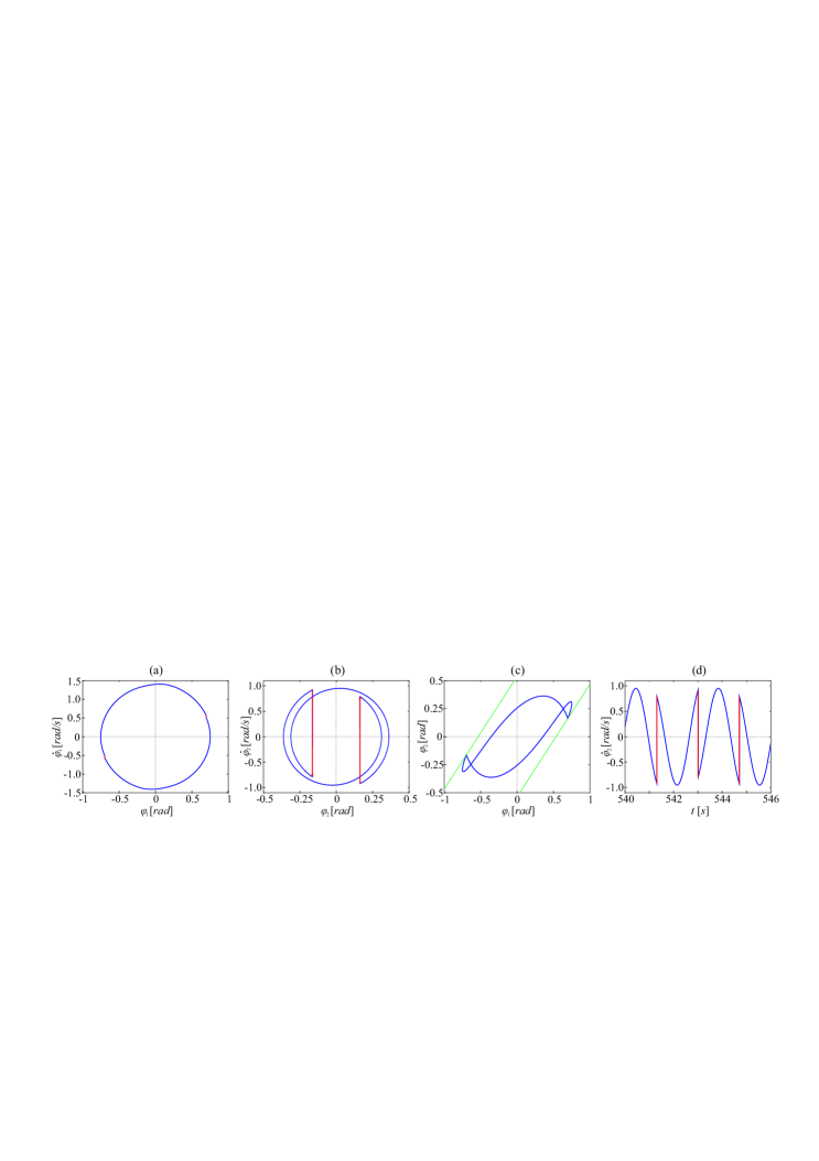
We can distinguish a symmetric type of falling clapper with collisions per one period of motion and its asymmetric version with impact per period. Although the course of the collision is similar in both cases they are completely different for the listeners as the time interval between successive impacts is almost doubled in the asymmetric case. In Figs . 3.1 and 3.2 we present two types of falling clapper ringing scheme.
3.2 Flying clapper
If the collisions between the bell and the clapper occur when they perform in-phase motion we say that the bell works in a “flying clapper” manner. In this regime the amplitude of the clapper’s motion is larger than the bell’s and the clapper’s velocity sign remains the same after the collisions. The collisions have more gentle characteristic and the amount of energy that is transferred during the impact is much smaller than in “falling clapper” ringing scheme. Therefore, sometimes it may be difficult to achieve nice resounding of the bell, but the risk of the crack or damage is significantly decreased. In Figs. 3.3 and 3.4 we present two types of “flying clapper” behavior: symmetric attractor with impacts per period and asymmetric one with only impact per period respectively.
3.3 Double kiss
The “double kiss” is the name of working regime in which we observe impacts per one period of motion. During one period the clapper hits each side of the bell’s shell twice. The first collision on each side is in the “falling clapper” manner while the second impact has “flying clapper” course. This behavior is especially attractive for the listeners. Still, it is rarely met mainly because it is difficult to achieve. In the next Section we precisely determine conditions (ranges of parameters and ) for which we can observe this working regime. In Fig. 3.5 we show the characteristics of “double kiss”.
3.4 Sticking clapper - sliding dynamics
“Sticking clapper” is the name of working regime in which the clapper and the bell remain in contact for a certain amount of time. In other words the “sticking clapper” refers to the attractors that contain sliding mode. This working regime is typical for the bells mounted and operated in the English manner. In the considered system prior the sliding mode we observe a number of successive impacts (usually ) that have a “falling clapper” course. The energy amount that is transferred between the bell and the clapper decreases with each subsequent collision. Hence, the sound effects caused by each hit are different and not all collisions may be noticed by the listener. Moreover, when the clapper remains in the contact with the bell’s shell it also influences the produced sound. All these features have to be taken into consideration if we want the bell to sound nicely.
3.5 No impacting attractors and other possible solutions
If the forcing amplitude is not sufficient or the yoke is designed improperly, we can observe stable periodic attractor with no collisions. In such conditions no sound is produced and the bell can not work as a musical instrument. Unfortunately, no impacting attractors occur in wide range of and and even nowadays it is common that we have to redesign the yoke to make ringing possible. Apart from the ringing schemes described in this Section we can indicate other periodic attractors that can be successfully employed. For example we can observe asymmetric flying clapper behavior with doubled period and impacts per period. Such behavior can be easily taken as a typical falling clapper. Similarly, a quasi-periodic attractor with almost equal time intervals between the subsequent impacts can sound almost like a periodic ringing scheme. Moreover, as we proved in our previous publication [13], the course of successive collisions can differ a bit. Hence, in practical applications we do not demand strictly periodic behavior. Instead, we want to receive similar collisions of a presumed type in a possibly equal time intervals. Still, when designing the yoke and the propulsion of the bell we should always look for conditions that ensure periodic behavior as it increases the probability that the real system will work properly and reliably.
4 Influence of the yoke design and forcing amplitude on the system’s dynamics
4.1 One parameter diagram - transitions between different working regimes
In Fig. 4.1 we present one parameter diagram that presents how the system behaves with varying value of parameter. We assume and analyze the dynamics of the system for . Each time we start integration form zero initial conditions (, , , ), hence it is not a bifurcation diagram (the bell and the clapper always start their motion from hanging down position with zero velocities). We investigate the behavior of the system after minutes of preliminary motion (the analysis of influence of transient time on the system’s dynamics is shown in the end of this Section). To determine in which regime the system operates, we use two indicators. The first is the absolute value of the clapper’s angular velocity when the clapper passes the downward vertical . The second is the clapper’s velocity just after the clapper to the bell impact . Moreover, we calculate the energy dissipated at instant of collision . We record these values during the period of two minutes. Subplots (a) and (b) of Fig. 4.1 correspond to the first and the second indicator respectively while in lower part of the Figure (subplot (d) ) we present the energy dissipation. Analyzing Fig. 4.1 (a,b) we can asses the periodicity and the symmetry of the attractor. Moreover, we are able to evaluate the number of collisions per period of motion. To determine if we observe the “flying clapper” or “falling clapper” ringing scheme, we have to look at the phase portrait of the clapper or at least value of the clapper angular velocity just before the impact . We focus on the clapper’s motion because the changes in the bell’s behavior are often imperceptible due to its much bigger mass and inertia.
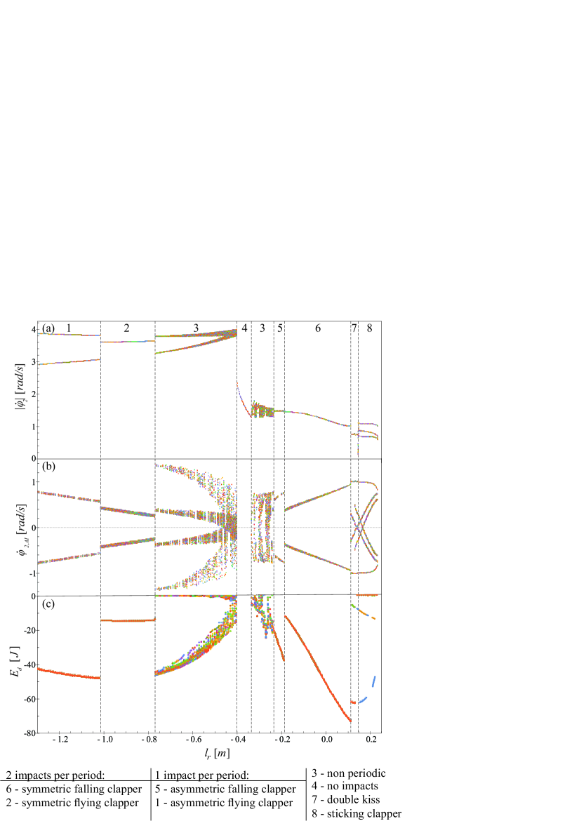
The two most common ringing schemes are symmetric “flying” and “falling” clapper. Analysing subplot (c) of Fig. 4.1 we see that in “flying clapper” working scheme collisions have gentle course and the risk of damage of the bell or the clapper is minimal. In this regime the amount of energy dissipated during collision is relatively small and do not depend on the yoke design. Conversely in “falling clapper” ringing scheme the amount of energy dissipated at instant of collision strongly depends on the yoke design. Collisions are more abrupt but still the bell can operate reliably if the and parameters are properly chosen. The risk of failure is also higher for asymmetric attractors (both “falling” and “flying” clapper) because then the amount of energy transferred during collisions is significantly higher than in symmetric case (for similar parameters’ values). That is why these working regimes are rarely met.
Vertical lines in Fig. 4.1 mark the ranges of where given working regimes can be observed. We see that transitions between different states of the system are sudden and sometimes even minor changes in the yoke geometry can result in a completely different behavior of the system. We usually expect the bells to work reliably for decades without any maintenance. Therefore, the yoke and the propulsion of the bell should be designed to ensure that the instrument will work properly regardless of small changes of influencing parameters. Such approach requires the in-depth knowledge of the systems dynamics.
4.2 Two parameters ringing scheme diagrams
To examine how the yoke’s design - described by parameter - and the amplitude of forcing - parameter - influence the system’s dynamics we perform the series of numerical simulations. In our analysis we consider the following ranges of these parameters: and . We take equally spaced values of (with the step ) and combine each with values of (from to with the step ). That gives us different sets of system’s parameters. For each one we simulate the system’s motion starting from zero initial conditions (, , , ).
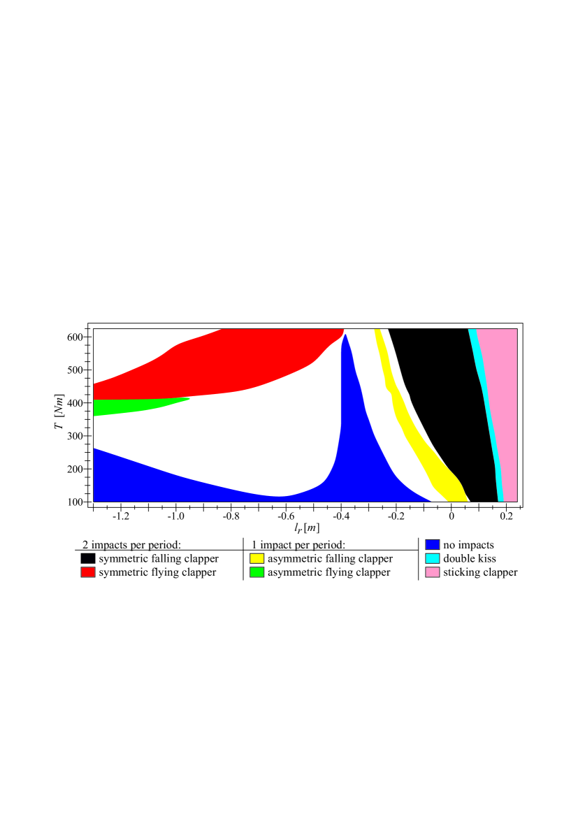
In Figs. 4.3 and 4.2 we show the possible behavior of the systems minute and minutes after the excitation started respectively. We call these two parameters plots as the “ringing scheme diagrams” because they allow to determine which ringing scheme can be achieved for the given values of and . We consider most characteristic types of the bells behavior that are described in detail in the previous Section. Of course many different stable attractors can exist for a given set of parameters and , but during our investigation we concern only the solutions that basins of attraction contain zero initial conditions (, , , ). As we mention before, we do so because in most cases the bell and the clapper start their motion from hanging down position with zero velocities. Another aspect that we consider is the transient time needed to reach a given attractor. It is important in real applications because the launching procedure of the bell should be possibly short. Hence, when designing the yoke and the propulsion mechanism we have to know both how presumed ringing scheme can be achieved as well as the time of transient behavior before we reach that attractor. If this time is too long we can either change the yoke design or apply special starting procedure - by the control of the driving motor.
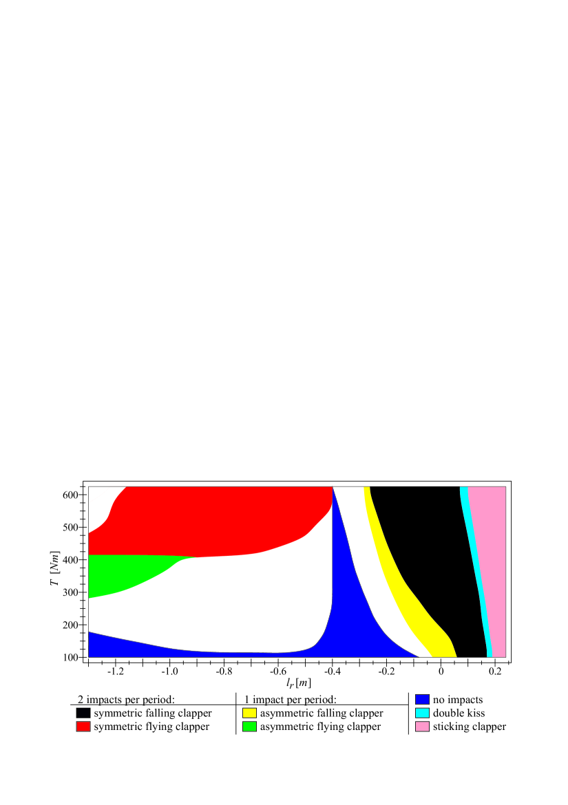
The first plot - Fig. 4.2 - presents the state of the system minutes after the propulsion starts. It shows which stable attractor will be achieved starting from zero initial conditions for different values of and . Hence, Fig. 4.2 indicates which ringing scheme can be obtained with given type of yoke and maximal driving torque. Analyzing the plot we can draw the following conclusions. The biggest areas correspond to the three most common ringing schemes: “falling clapper” (black) and “flying clapper” (red) with 2 impacts per one period of motion and “sticking clapper” (pink) that is typical for the bells mounted in the English manner. This means that these behaviors are relatively easy to achieve and remain even after long period of time when values of some parameters can change a bit (for example maximum torque generated by the linear motor).
Generally, the design of the yoke determines how the bell will operate. For we can observe “flying clapper” with (red) or (green) impacts per period but these ringing schemes can be achieved only when is bigger than some threshold. The threshold value decreases with the decrease of that causes the growth of the inertia of the yoke-bell assembly with respect to its axis of rotation. If is not sufficient we will not observe any impacts (blue) or the system will reach different attractor (white) - periodic or non-periodic one. For we cannot obtain any of the analyzed ringing schemes no matter how big the forcing amplitude is. This proves that when the yoke is designed improperly it may be impossible to force the system to ensure proper operation. For the system can work in the following manner: “falling clapper” with (yellow) or (black) impacts per period, “double kiss” (light blue) or “sticking clapper” (pink). Each of these ringing schemes can be achieved despite the value of but the yoke should be designed for the purpose. Hence, for these working regimes there is no need to use very powerful driving motors and the system can work more efficiently.
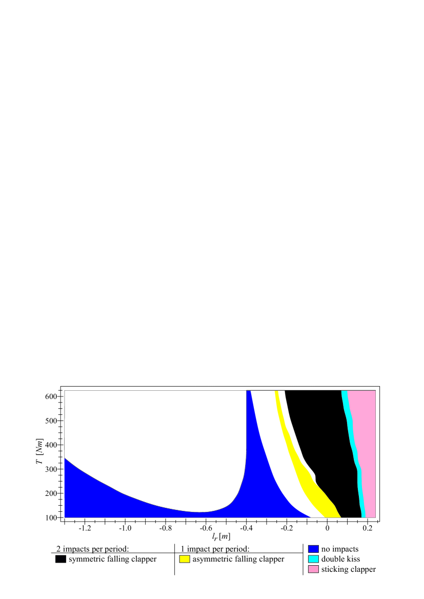
In real applications we usually cannot accept launching times bigger than two minutes. To determine for which parameters the start up procedure runs quickly, we calculate the second plot - Fig. 4.3 - that shows the state of the system two minutes after the propulsion started. In this case we analyze the system’s motion for and do not demand to reach the stable solution. Instead, we check if for the average observer the behavior of the system could be seen as proper and regular. For example we do not care if the amplitude of the bell’s motion is still slightly rising and just check if the period between the successive impacts is constant and the collisions have recurrent course. Comparing Figs. 4.2 and 4.3 we see that the difference in the size of areas is especially visible for . The range that corresponds to the attractor without impacts (blue color) is significantly larger and we cannot observe any “flying clapper” ringing schemes. This means that these working regimes not only requires larger amplitude of forcing but also longer transient time before the system reaches presumed solution. Therefore, in practical applications we often apply special launching procedure to decrease the time of transient behavior. We also see that for the areas corresponding to different ringing schemes are almost identical to the ones presented in Fig. 4.2. The main difference is that for there is a white region between the areas corresponding to asymmetric (yellow) and symmetric (black) “falling clapper”. Therefore, special starting techniques are rarely required if the yoke design ensures small inertia with respect to the bell’s rotational axis.
Another important conclusion from the analysis of the ringing scheme diagrams is the possibility to design the yoke and the propulsion to enable more than one ringing scheme. For example, assuming that we will observe “falling clapper” with impact per period for and impacts per period for . Hence, if the adopted driving motor enables to adjust the output torque in a sufficiently wide range, we can change the way the bell operates. Thanks to that, we are able to differentiate the tune of the bell for different occasions.
4.3 Example of the launching procedure
The results presented in the previous Subsection prove that we often have to use special launching procedure in order to achieve presumed ringing schemes and maintain considerably short starting time. In this Section we propose a simple control of the driving motor that enables to achieve all considered working regimes after only two minutes. We assume that launching procedure takes seconds and over that time we adjust the maximum torque that is generated by the motor. Hence, during the first seconds, instead of using formula 2.4 to describe the generalized momentum generated by the propulsion mechanism, we use the following function:
| (4.1) |
where: is time and , are control parameters. We obtained the above formula basing on the following assumptions. The amplitude of forcing decreases as a square function and for it is equal to parameter . Hence, there is no jump in the torque generated by the motor when the launching procedure ends () and we switch back to formula 2.4. Analyzing Figs. 4.2 and 4.3 we see that the launching procedure is needed especially for small and large . Therefore, we assume that the maximal value of generated torque should increase with the increase of and the absolute value of .
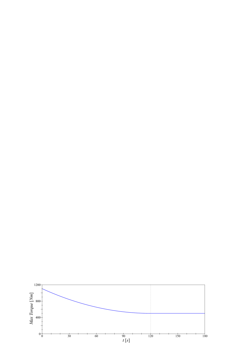
In Fig. 4.4 we show how the maximum torque generated by the linear motor (for and ) changes during the analyzed first minutes of the system’s motion. The dotted vertical line in Fig. 4.4 marks the time when the launching procedure ends and the output of the motor stabilizes.
In Fig. 4.5 we present the ringing scheme diagram obtained for the system with applied launching procedure that is described above. Similarly to Fig. 4.3, this time we also do not require the system to reach the stable attractor and just check if its behavior could be perceived as proper by an average listener. Analyzing Fig. 4.5 we see that even using simple control of the driving motor we can achieve satisfactory results and decrease the time of the transient motion. Moreover, obtained results prove that formula 4.1 - universal for all and - allow us to achieve good results in a wide range of parameters values. But, the proposed control is not efficient with respect to the systems with large forcing amplitude and yoke design that provides large inertia of the bell (left upper part of the plot.). Comparing Figs. 4.2 and 4.5 we see the difference in the borders and sizes of the areas corresponding to different working regimes, but still thanks to the proposed launching procedure we can reach all considered working regimes. Hence, the proposed control allow us to obtain all considered ringing schemes but they appear in smaller ranges of parameters values. Therefore, in some cases there is a need to adjust the launching procedure to shorten transient time and reach presumed behavior of the system.
5 Conclusions
Hybrid dynamical model of the yoke-bell-clapper system can exhibit a plethora of different dynamical behaviors but only a few of them can be considered as a proper working regimes of the instrument. Therefore, the yoke of the bell and its propulsion mechanism should be designed to ensure the system will behave correctly and sound nicely. In case of bells with typical shape and mass engineers usually design yokes basing on their experience and local tradition. Still, it is often a challenge to create a reliable suspension for unique bells and sometimes the mounting of the bell or its propulsion have to be redesigned to achieve presumed ringing scheme.
In the paper we present a method that can be used to determine the conditions under which given type of behavior can be achieved. We develop two parameter ringing scheme diagrams that describe how the geometry of the yoke and maximum output of the driving motor influence the dynamics of the system. Similar charts can be calculated for any bell and used to design its mounting and propulsion. Thus, we can ensure that the instrument will work properly and reliably regardless of small changes of parameters.
Moreover, analyzing the ringing scheme diagrams we see that it is possible to design the yoke and the propulsion to enable more than one ringing scheme with relatively small changes of motor and/or yoke parameters. Hence, we can easily differentiate the tune of the bell for different occasions.
Basing on the presented analysis we are able to determine the minimum required power of the driving motor and estimate the time that is needed to achieve given attractor. If the transient time is too long, special launching procedure has to be applied. We propose the control of the driving motor that enables to reach all considered ringing schemes after seconds of preliminary motion. It is possible to further optimize the launching procedure, but to get best results we need to know the values of all system’s parameters. Still, presented results are robust and prove that even simple and universal formula can be highly efficient in a wide range of systems’ parameters.
Acknowledgment
This work is funded by the National Science Center Poland based on the decision number DEC-2013/09/N/ST8/04343. We would especially like to thank the Parson of Cathedral Basilica of St Stanislaus Kostka Prelate Ireneusz Kulesza for his support and unlimited access to the bell. We have been able to measure the bell’s template thanks to the bell’s founder Mr Zbigniew L. Felczynski. The data on the clapper, the yoke and the motor have been obtained form Mr. Pawel Szydlak.
References
References
- Lum [2005] Glockentï¿œrme DIN 4178:2005-04, 2005.
- Ivorra and Cervera [2001] S. Ivorra and J. R. Cervera. Analysis of the dynamic actions when bells are swinging on the bell-tower of bonrepos i mirambell church (valencia, spain). IProc. of the 3rd international seminar of historical constructions, pages 413–19, 2001.
- Ivorra and Pallares [2006] S. Ivorra and F. J. Pallares. Dynamic investigations on a masonry bell tower. Engineering Structures, 28(5):660 – 667, 2006.
- Ivorra et al. [2009] S. Ivorra, F. J. Pallares, and J. M. Adam. Dynamic behaviour of a modern bell tower - a case study. Engineering Structures, 31(5):1085 – 1092, 2009.
- J. Heyman [1976] BD. Threlfall J. Heyman. Inertia forces due to bell-ringing. International Journal of Mechanical Sciences, 18:161–164, 1976.
- J. Wilson [1993] A. Selby J. Wilson. Durhamm cathedral tower vibrations during bell-ringing. In Proceedings of the conference engineering a cathedral., pages 77–100. London: Thomas Telford, 1993.
- J. Wilson [1997] A. Selby J. Wilson. Dynamic behaviour of masonry church bell towers. In Proceedings of the CCMS symposium, pages 189–199. New York: Chicago ASCE, 1997.
- Klemenc et al. [2011] J. Klemenc, A. Rupp, and M. Fajdiga. A study of the dynamics of a clapper-to-bell impact with the application of a simplified finite-element model. Engineering with Computers, 27(3):261–272, 2011.
- Klemenc et al. [2012] J. Klemenc, A. Rupp, and M. Fajdiga. Dynamics of a clapper-to-bell impact. International Journal of Impact Engineering, 44(0):29 – 39, 2012.
- Lepidi et al. [2009] M. Lepidi, V. Gattulli, and D. Foti. Swinging-bell resonances and their cancellation identified by dynamical testing in a modern bell tower. Engineering Structures, 31(7):1486 – 1500, 2009.
- Meneghetti and Rossi [2010] G. Meneghetti and B. Rossi. An analytical model based on lumped parameters for the dynamic analysis of church bells. Engineering Structures, 32(10):3363 – 3376, 2010.
- Muller [1986] FP. Muller. Dynamische und statische gesichtspunkte beim bau von glockenturmen. Karlssruhe: Badenia Verlag GmbH, pages 201–212, 1986.
- P. Brzeski [2015] P. Perlikowski P. Brzeski, T. Kapitaniak. Experimental verification of a hybrid dynamical model of the church bell. International Journal of Impact Engineering, 2015.
- Schutz [1994] KG. Schutz. Dynamische beanspruchung von glockenturmen. Bauingenieur, 69:211–217, 1994.
- Spielmann et al. [2008] R. Spielmann, A. Rupp, M. Fajdiga, and B. Aztori. Kirchenglocken-kulturgut, musikinstrumente und hochbeanspruchte komponenten. Glocken-Lebendige Klangzeugen. Schweizerische Eidgenossenschaft, Bundesamt fur Kultur BAK., pages 22–39, 2008.
- Steiner [1986] J. Steiner. Neukonstruktion und sanierung von glockenturmen nach statischen und dynamischen gesichtspunkten. Karlssruhe: Badenia Verlag GmbH, pages 213–237, 1986.
- Veltmann [1876] W. Veltmann. Uerber die bewgugn einer glocke. Dinglers Polytechnisches Journal, 220:481–494, 1876.
- Veltmann [1880] W. Veltmann. Die koelner kaiserglocke. enthullungen uber die art und weise wie der koelner dom zu einer miï¿œrathenen glocke gekommen ist. Hauptmann, Bonn, 1880.