Experimental Scattershot Boson Sampling
Boson Sampling is a computational task strongly believed to be hard for classical computers, but efficiently solvable by orchestrated bosonic interference in a specialised quantum computer. Current experimental schemes, however, are still insufficient for a convincing demonstration of the advantage of quantum over classical computation. A new variation of this task, Scattershot Boson Sampling, leads to an exponential increase in speed of the quantum device, using a larger number of photon sources based on parametric downconversion. This is achieved by having multiple heralded single photons being sent, shot by shot, into different random input ports of the interferometer. Here we report the first Scattershot Boson Sampling experiments, where six different photon-pair sources are coupled to integrated photonic circuits. We employ recently proposed statistical tools to analyse our experimental data, providing strong evidence that our photonic quantum simulator works as expected. This approach represents an important leap toward a convincing experimental demonstration of the quantum computational supremacy.
Introduction
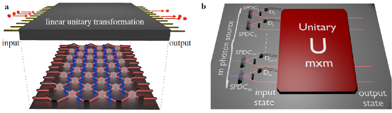
Theory has shown that quantum computers should be able to markedly outperform conventional, classical computers in specific tasks Preskill12 . In practice, however, no quantum computer has yet solved a problem instance which is hard to solve classically. With the goal of rigorously establishing what was called quantum supremacy, in 2010 Aaronson and Arkhipov provided strong theoretical evidence that a simpler, specialised quantum computer could solve a classically-hard computational task Aaronson10 . The so-called Boson Sampling problem consists in sampling from the output distribution of indistinguishable photons entering different input modes of a given -mode random interferometer (see Fig. 1a). The complex multi-photon interference within the device was shown, under mild computational assumptions, to yield an output distribution that is hard to sample using classical computers. The difficulty has been traced back to the known intractability of calculating the permanent function of a matrix Valiant79 . Indeed, each output’s probability amplitude is given by the permanent of a different matrix obtained from the unitary matrix describing the interferometer Aaronson10 ; Troyansky96 ; Scheel04 .
Because a photonic Boson Sampling computer does not use adaptive measurements, it falls short of the requirements Ladd2010 ; KLM01 for a universal quantum computer capable, for example, of factoring integers efficiently Shor97 . On the other hand, its comparatively simple design has prompted a number of small-scale implementations using the interference of 3 photons injected over different modes in integrated interferometers with up to 13 modes Broome2013 ; Spring2013 ; Till2012 ; Crespi2012 ; Spagnolo2013 ; Spagnolo2013a ; Carolan2013a . First estimates have shown that 30 photons evolving in an interferometer with about 100 modes would already be extremely demanding to simulate classically, providing strong experimental evidence for the quantum computational supremacy. Moreover, Boson Sampling is an experimental platform suitable for addressing important intermediate challenges for the field of quantum computation, such as benchmarking and certification of medium-scale devices Gogolin2013 ; Aaronson13 ; Spagnolo2013a ; Carolan2013a . There have been recent theoretical investigations on allowable error tolerances Rohde12 ; Leverrier2013 as well as a recent proposal for an implementation using phonons in ion traps Lau2012 ; Shen2013 . The technologies enabling a Boson Sampling computer are useful also for other photonic applications such as quantum cryptography RevModPhys.74.145 and universal photonic quantum computation KLM01 ; Kok2007 .
One of the main difficulties in scaling up the complexity of Boson Sampling devices is the requirement of a reliable source of many indistinguishable photons. Despite recent advances in photon generation Eisaman2011 using atoms atoms2 , molecules molecules3 ; molecules2 , colour centers in diamond color and quantum dots Qdot3 ; Qdot4 , currently the most widely used method remains parametric downconversion (PDC) SPDC1 ; SPDC2 . This approach requires pumping a nonlinear crystal with an intense laser to generate pairs of identical photons. The main advantages of PDC sources are the high photon indistinguishability, collection efficiency and relatively simple experimental setups. This technique, however, suffers from two drawbacks. First, because the nonlinear process is non-deterministic, so is the photon generation, even though it can be heralded. Second, the laser pump power, and hence the source’s brilliance, has to be kept low to prevent unwanted higher-order terms in the photon generation process. These two characteristics have, so far, restricted PDC implementations of Boson Sampling experiments to proof-of-principle demonstrations with 3 photons only in the original spirit of Boson Sampling (one photon per mode, injected over different modes).
Recently, a new scheme has been proposed to make the best use of PDC sources for photonic Boson Sampling, greatly enhancing the rate of -photon events Lund2013 ; AaronsonBlog . This approach has been named Scattershot Boson Sampling in Aaronson’s blogAaronsonBlog and involves connecting () PDC heralded single-photon sources to different input ports of the interferometer (see Fig. 1b). Suppose each PDC source yields a single photon with probability per pulse. By pumping all PDC crystals with simultaneous laser pulses, photons will be simultaneously generated in a random (but heralded) set of input ports with probability , which for represents an exponential improvement in generation rate with respect to usual, fixed-input Boson Sampling with sources. The Scattershot Boson Sampling problem, naturally solvable by this setup, is to sample from the output distribution of a given, random interferometer for random sets of input modes.
Note that the pump laser power does not need to be increased -fold, as the laser can sequentially pump each PDC source with very little loss to down-converted photons. In this way, the ratio between one-pair production rate and higher order terms can be kept low. Another interesting feature of this scheme is the possibility of recording events corresponding to different numbers of injected photons. All these characteristics suggest that the Scattershot approach to Boson Sampling will be decisive in future, larger experiments designed to reach the quantum supremacy regime.
Here we report experimental results on Scattershot Boson Sampling experiments using a -mode integrated photonic chip. We use up to six PDC photon sources to obtain data corresponding to 2- and 3-photon interference, and validate the device’s functioning using recently proposed statistical tests Aaronson13 ; Spagnolo2013a . Additional results on a different 9-mode chip are also presented and certified, thus showing the robustness of the Scattershot approach. Finally, we use numerical calculations to discuss the complexity of Boson Sampling simulation and certification, and to estimate a benchmark for quantum supremacy.
Scattershot Boson Sampling experiment
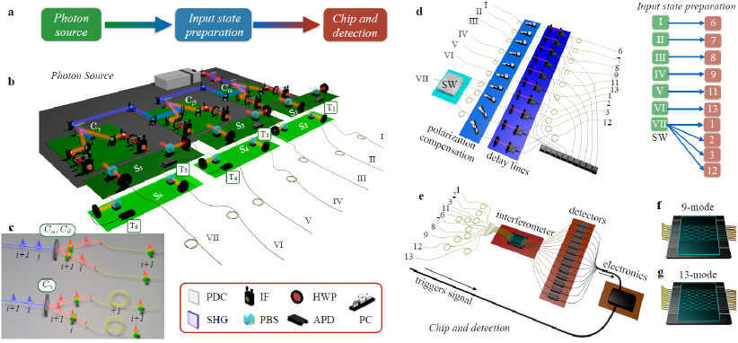
A photonic Scattershot Boson Sampling experiment involves a few experimentally demanding steps (see Fig. 2a). First, PDC sources are used to generate indistinguishable photons in a heralded, but random, set of modes. The input state must then be prepared (introducing time delays and polarisation compensation) to be injected into the -mode integrated interferometer. We must then detect -fold coincident photon counts at the chip’s output modes, all the while maintaining synchronisation so that we have true -photon interference in the chip. Finally, it is necessary to analyse the output data to validate the correct functioning of the device.
For our experiments we fabricated two integrated photonic chips implementing random multimode interferometers (with 9 and 13 modes), using a femtosecond laser writing technique gattass2008flm ; Marshall09 ; corrielli2014rotated ; heilmann2014arbitrary described in the Methods section. For the 9-mode chip, the input state was created by a 4-photon PDC source (crystal in Fig. 2b), with one of the photons used as a trigger. Our preliminary experiment involved simulating the statistics of a Scattershot Boson Sampling experiment in the 9-mode chip by manually connecting 20 different sets of input modes to the source, via a fiber array, and uniformly mixing the data corresponding to different input states.
We used the 13-mode chip to implement Scattershot Boson Sampling experiments with a total of six PDC sources ( to in Fig. 2b). We simplified the implementation by enfolding two equal sources in each crystal, corresponding to the two possible vertical/horizontal polarization combinations for the photon pair generated. Hence, the six sources - are created using only the three crystals , and . Each PDC source ideally produces two indistinguishable photons. One such source (Source ) prepares photons I and III, which enter the interferometer in fixed modes 6 and 8, respectively. The other five PDC sources produce random, but heralded, single photons, which are coupled to different input ports of the chip via a polarisation correction stage, delay lines, and a single-mode fiber array, according to the map in Fig. 2d. Note that we further increased the input variability by distributing photon VII randomly among four different input ports, via an optical fiber switcher with switching rate comparable to the obtained experimental count rate. This raises from five to eight the number of possible input sets, allowing us validation procedure tests on data sampled from a larger number of input-output configurations.
For both chips, the output photons are collected by a multimode fiber array, and multiphoton coincidences are detected by avalanche photodiodes, coordinated by an electronic data acquisition system capable of registering events with an arbitrary number of photons. We then analyzed data corresponding to 2- and 3-photon interference inside the chip. Synchronizing up to six PDC sources distributed over 10 input modes is a technically difficult step; once that was achieved, the controllable, relative delays between photons allowed us to adjust their degree of distinguishability. Further details about synchronization procedures and indistinguishability between photons of different sources are given in the Supplementary Materials.
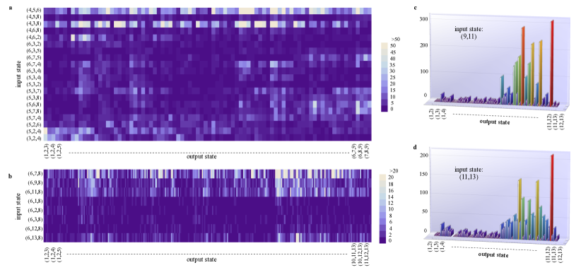
The observed number of events corresponding to each input/output combination for the 9- and 13-mode chips are shown respectively in Figs. 3a and 3b.
Note the sparseness of the data set, as only a few events corresponding to each input/output combination are observed (if any). This is an expected feature of more complex Boson Sampling experiments whose number of possible input-output combinations may far exceed the number of observed events. Furthermore, in Figs. 3c and 3d we show the results for 2-photon experiments, in which each input is a doubly-heralded 2-photon state.
Another route to more complex Boson Sampling experiments is time-multiplexing Pittman ; Jeffrey ; Migdall ; McCusker ; Zeilinger , that is, exploiting interference of photons created by different pump pulses on the same PDC source. Ultra-fast optical switchers can be used to distribute the photons generated by subsequent pump pulses to different input ports of the photonic chip, after suitable synchronisation delays. This type of time-multiplexing increases the -photon generation, using a fixed number of PDC sources. Our experiments with the 13-mode chip feature a first proof-of-principle demonstration of interference among photons generated by different pulses. This was done by introducing appropriate delays, so that photons from Sources and are produced by a different pump pulse than those generated by all the other sources (see Fig. 2c).
Validation of experimental Boson Sampling data
Unlike problems such as integer factoring, the full certification of the correct functioning of a Boson Sampling device is by itself a hard computational problem Aaronson10 ; Gogolin2013 ; Aaronson13 ; Aolita14 ; PhysRevLett.113.020502 . There are, however, statistical tests able to provide partial certification against a number of sensible hypotheses about how the device may be failing to sample from the correct, ideal distribution. Boson Sampling thus serves as a useful test bench for the more general problem of quantum device certification. We now discuss the results of the application of validation tests designed for standard Boson Sampling experiments to our Scattershot scenario.
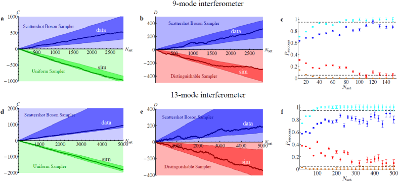
The first test we applied to our data is the scalable statistical test proposed by Aaronson and Arkhipov in Ref. Aaronson13 , initially designed to distinguish fixed-input Boson Sampling events from a uniform distribution over the possible outputs and here extended to the Scattershot scenario. This is achieved by calculating, for each observed event, a discriminator which weakly correlates with the Boson Sampling probability, but which can be calculated efficiently Spagnolo2013a . The result for the 9-mode chip is reported in Fig. 4a; at variance with the test performed in Ref. Spagnolo2013a , instead of a single input our 9-mode chip experiments allowed for 1680 different input-output combinations. We have also applied the test to data obtained from the 13-mode chip, and the results are reported in Fig. 4d; in this case, there were 2288 different input/output combinations.
A second test we performed is an adaptation of a standard likelihood ratio test CoverThomas06 , with the goal of comparing our experimental data with those expected if distinguishable photons were used. For each experimental outcome, the probabilities for indistinguishable and distinguishable photons are compared (more details on the tests are reported in the Methods section and in the Supplementary Materials). The results of this test for the 9-mode and 13-mode chips are shown respectively in Figs. 4b and 4e. Note that, again, in both cases we applied the test to the data set combining all different input states used.
Successful validation could be obtained even with small data sets. This is highlighted in Figs. 4c for the 9-mode chip and 4f for the 13-mode chip, where we plot the trend of the test’s success rate against the size of the data set used.
Discussion
In summary, we have reported the first experimental implementation of the Scattershot approach to photonic Boson Sampling, recently proposed in Lund2013 ; AaronsonBlog , a promising way of exponentially scaling up the computational power of the quantum sampler.
Our experiments use 6 PDC sources in parallel to demonstrate the feasibility of non-trivial realizations of this approach. In the experimental implementation, due to non-optimal beam propagation and PDC sources, we observed an increase in the event rate by a factor 4.5 (3.4), compared to standard Boson Sampling with a source of average (best) brightness. This value should be compared to the expected value of 5.
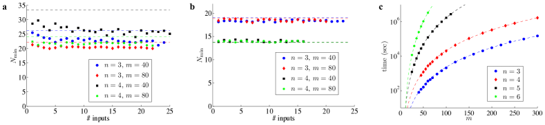
Let us now discuss how Scattershot Boson Sampling may bring within reach an experimental regime approaching quantum supremacy. Let us consider experiments with events, more than sufficient to perform a successful validation of the Scattershot Boson Sampler (see Figs. 5a and 5b). In this regime, with high probability each recorded event is sampled from a different input state, provided that , and assuming the use of one PDC source per input mode. To get an insight into the hardness of calculating the whole output distribution corresponding to each input used, we illustrate the required computational time on a standard laptop in Fig. 5c. Although this brute force calculation is currently the only reported approach for a classical Boson Sampling simulation, it is likely that more efficient classical sampling algorithms are possible for interferometers chosen uniformly at random, but no description of those has yet been reported in the literature PrivateComm .
The main advantage of the Scattershot approach is to markedly decrease the experimental run-time with respect to the usual, fixed-input Boson Sampling setup. Using challenging but feasible experimental parameters for pulse rate (80 MHz), per-pulse generation probability (0.015), triggering efficiency (0.5) and overall photon counting probability (0.15, which takes into account both photon losses in the injection-propagation stage, linearly dependent from the chip size, and detector inefficiencies), we get an estimated runtime of seconds for a -event, fixed-input Boson Sampling experiment with , . The corresponding Scattershot Boson Sampling experiment uses PDC sources in parallel, resulting in a quantum runtime of seconds. These estimates clearly illustrate the boost in computational speed provided by the Scattershot approach.
Validation of the Scattershot Boson Sampler would still be feasible well into the quantum supremacy regime, as the number of events whose probabilities need to be calculated by a classical computer to certify the proper operation of the quantum device is very low and almost independent on the number of photons and modes involved (see Figs. 5a and 5b). This is expected to hold for validation of experiments with up to about 30 photons.
Note that the simulations of Fig. 5 did not take into account errors such as partial photon distinguishability and other experimental imperfections. In larger devices, for example, a spurious but genuine-looking event could result from the loss of triggered photons and simultaneous injection of untriggered photons. A precise analysis of the effect of incorrectly heralded photons in our experiments is carried out in the Supplementary Materials. These events count as white noise in the validation tests, slightly lowering the test’s efficiency (see the Supplementary Materials section for more details). This particular problem can be overcome by using the heralding detectors to briefly open an optical shutter in the corresponding input mode, as discussed in the Supplementary Materials.
Other photon source schemes, such as collecting larger number of modes from degenerate PDC type I radiation via microlenses Rossi09 , as well as novel approaches using time-bin encoding Motes14 are all promising routes to scale up the complexity of future Boson Sampling experiments. Further theoretical progresses could also help in this endeavor, such as the development of scalable statistical validation tests against other alternative distributions. Recent proposals along these lines are based on looking at global coalescence effects Carolan2013a , checking specific output suppressions in interferometers with certain symmetries PhysRevLett.113.020502 , or performing single-mode homodyne detection Aolita14 . Moreover, it has been argued that there are other classes of quantum states that can be used for Boson Sampling without spoiling its computational complexity Dowling1 ; Sesha2014 ; future research in this direction could help to simplify the experimental implementation of hard-to-simulate devices.
Methods
Fabrication of integrated optics devices
Multimode integrated interferometers are fabricated in Eagle2000 (Corning) alumino-borosilicate glass by femtosecond laser direct writing. Focused ultrashort pulses induce permanent refractive index changes in the focal volume by nonlinear absorption mechanisms. Buried waveguides are directly drawn in the volume of the glass by suitably translating the sample with respect to the writing beam. This direct-write technique allows fast realization of custom integrated optical circuits with large design freedom. A cavity dumped Yb:KYW mode-locked oscillator, producing laser pulses with 300 fs duration, 1 MHz repetition rate and 1030 nm wavelength, is employed. In particular, irradiation is performed by focusing 220 nJ pulses with a 0.6 NA microscope objective and by translating the sample at 40 mm/s constant speed, to obtain single-mode waveguides for 785 nm photons. Average waveguide depth below the sample surface is 170 m. Interferometers implementing random unitary matrices are obtained by cascading several rows of balanced (50:50) directional couplers, with the layouts in Figs. 2f and 2g, connected by S-bends of slightly different lengths, which induce controlled (though randomly chosen) phase shifts Crespi2012 . Each directional coupler (including S-bends) is about 5 mm long, while input and output waveguides are 127 m spaced, for a global footprint of the circuits of about 35 mm 1.1 mm for the 9-mode device and 45 mm 1.6 mm for the 13-mode device.
Experimental details
Single photons were generated in six equal parametric down conversion (PDC) sources, implemented in three crystals. The 3-photon input state for the 9-mode chip was obtained by PDC generation from the first crystal, with one of the four emitted photons used as a trigger. The input states were then changed manually by connecting a fiber array to 20 different sets of input modes of the chip. The 13-mode chip was then used to implement the complete scattershot version of the Boson Sampling experiment. The three crystals reproduced six PDC sources, the first one belonging to the first crystal was adopted to inject two fixed input modes of the chip (number 6 and number 8), while another photon was injected shot by shot coming from one of the five remaining PDC sources. At the output of both chips, multimode fibers were connected to single photon counting detectors and an electronic data acquisition system allowed to register events with an arbitrary number of photons.
Validation of the experimental data
The validation against the hypothesis that the data are sampled according to a uniform distribution is performed by adopting the scalable Aaronson and Arkhipov test Aaronson13 experimentally verified in Spagnolo2013a . The validation test against the hypothesis that the data are sampled with distinguishable photons works as follows. For each experimental outcome , the certifier calculates the associated probabilities for indistinguishable photons and for distinguishable photons. A counter variable is increased (decreased) by 1 if (). After analysing all events, () indicates the hypothesis of indistinguishable (distinguishable) photons is more likely to hold. The probabilities and are calculated using the permanent formula, taking into account the partial photon distinguishability of the source, and the chip’s theoretical design parameters. For the 9-mode interferometer, the data were collected separately by manually changing the input state. Then, the recorded events before the validation procedure are mixed uniformly in order to represent a set of data collected with a random input state.
The same validation procedure was carried out for the 2-photon data, which were collected simultaneously to the 3-photon ones. In particular, photons from inputs 11 and 13 are generated from two different laser pulses. We obtained an average success probability of the validation process after a data set size of against the Uniform distribution and of against the distribution with distinguishable photons.
References
- (1) J. Preskill. Quantum computing and the entanglement frontier. arXiv:1203.5813, 2012.
- (2) S. Aaronson and A. Arkhipov. The computation complexity of linear optics. In Proceedings of the 43rd annual ACM symposium on Theory of computing, San Jose, 2011 (ACM press, New York, 2011), pages 333–342, 2011.
- (3) L. G. Valiant. The complexity of computing the permanent. Theoretical Comput. Sci., 8(2):189–201, 1979.
- (4) L. Troyansky and N. Tishby. Permanent uncertainty: On the quantum evaluation of the determinant and the permanent of a matrix. In Proceedings of PhysComp, 1996.
- (5) S. Scheel. Permanents in linear optical networks. arXiv:quant-ph/0406127v1, 2004.
- (6) T. D. Ladd, F. Jelezko, R. Laflamme, Y. Nakamura, C. Monroe, and J. L. O’Brien. Quantum computers. Nature, 464:45–53, 2010.
- (7) E. Knill, R. Laflamme, and G. J. Milburn. A scheme for efficient quantum computation with linear optics. Nature, 409:46–52, 2001.
- (8) P. W. Shor. Polynomial-time algorithms for prime factorization and discrete logarithms on a quantum computer. SIAM J. Comput., 26:1484–1509, 1997.
- (9) M. A. Broome, A. Fedrizzi, S. Rahimi-Keshari, J. Dove, S. Aaronson, T. C. Ralph, and A. G. White. Photonic boson sampling in a tunable circuit. Science, 339:794–798, 2013.
- (10) J. B. Spring, B. J. Metcalf, P. C. Humphreys, W. S. Kolthammer, X.-M. Jin, M. Barbieri, A. Datta N. Thomas-Peter, N. K. Langford, D. Kundys, J. C. Gates, B. J. Smith, P. G. R. Smith, and I. A. Walmsley. Boson sampling on a photonic chip. Science, 339:798–801, 2013.
- (11) M. Tillmann, B. Dakic, R. Heilmann, S. Nolte, A. Szameit, and P. Walther. Experimental boson sampling. Nature Photonics, 7:540–544, 2013.
- (12) A. Crespi, R. Osellame, R. Ramponi, D. J. Brod, E. F. Galvão, N. Spagnolo, C. Vitelli, E. Maiorino, P. Mataloni, and F. Sciarrino. Integrated multimode interferometers with arbitrary designs for photonic boson sampling. Nature Photonics, 7:545–549, 2013.
- (13) N. Spagnolo, C. Vitelli, L. Sansoni, E. Maiorino, P. Mataloni, F. Sciarrino, D. J. Brod, E. F. Galvao, A. Crespi, R. Ramponi, and R. Osellame. General rules for bosonic bunching in multimode interferometers. Phys. Rev. Lett., 111:130503, 2013.
- (14) N. Spagnolo, C. Vitelli, M. Bentivegna, D. J. Brod, A. Crespi, F. Flamini, S. Giacomini, G. Milani, R. Ramponi, P. Mataloni, R. Osellame, E. F. Galvão, and F. Sciarrino. Experimental validation of photonic boson sampling. Nature Photonics, 8:615–620, 2014.
- (15) J. Carolan, J. D. A. Meinecke, P. J. Shadbolt, N. J. Russell, N. Ismail, K. Worhoff, T. Rudolph, M. G. Thompson, J. L. O’Brien, J. C. F. Matthews, and A. Laing. On the experimental verification of quantum complexity in linear optics. Nature Photonics, 8:621–626, 2014.
- (16) C. Gogolin, M. Kliesch, L. Aolita, and J. Eisert. Boson-sampling in the light of sample complexity. arXiv:1306.3995, 2013.
- (17) S. Aaronson and A. Arkhipov. Bosonsampling is far from uniform. Quantum Info. Comput., 14:1383-1423, 2014.
- (18) P. P. Rohde and T. C. Ralph. Error tolerance of the boson-sampling model for linear optics quantum computing. Phys. Rev. A, 85:022332, 2012.
- (19) A. Leverrier and R. Garcia-Patron. Analysis of circuit imperfections in BosonSampling Quantum Inf. Comput.,15:0489-0512 (2015).
- (20) H. Lau and D. James. Proposal for a scalable universal bosonic simulator using individually trapped ions. Phys. Rev. A, 85:062329, 2012.
- (21) C. Shen, Z. Zhang, and L.-M. Duan. Scalable implementation of boson sampling with trapped ions. Phys. Rev. Lett., 112:050504, 2014.
- (22) N. Gisin, G. Ribordy, W. Tittel, and H. Zbinden. Quantum cryptography. Rev. Mod. Phys., 74:145–195, Mar 2002.
- (23) P. Kok, W. J. Munro, K. Nemoto, T. C. Ralph, J. P. Dowling, and G. J. Milburn. Linear optical quantum computing with photonic qubits. Rev. Mod. Phys., 79:135–174, 2007.
- (24) M. D. Eisaman, J. Fam, A. Migdall, and S. V. Polyakov. Invited review article: Single-photon sources and detectors. Rev. Sci. Instrum., 82:071101, 2011.
- (25) M. Hijlkema, B. Weber, H. P. Specht, S. C. Webster, A. Kuhn, and G. Rempe. A single-photon server with just one atom. Nat. Phys., 3:253–255, 2007.
- (26) M. Steiner, A. Hartschuh, R. Korlacki, and A. J. Meixner. Highly efficient, tunable single photon source based on single molecules. Applied Physics Letters, 90(18), 183122, 2007.
- (27) R. Lettow, Y. L. A. Rezus, A. Renn, G. Zumofen, E. Ikonen, S. Götzinger, and V. Sandoghdar. Quantum interference of tunably indistinguishable photons from remote organic molecules. Phys. Rev. Lett., 104:123605, 2010.
- (28) C. Kurtsiefer, S. Mayer, P. Zarda, and H. Weinfurter. Stable solid-state source of single photons. Phys. Rev. Lett., 85:290–293, 2000.
- (29) A. J. Shields. Semiconductor quantum light sources. Nat Photon, 1:215–223, 2007.
- (30) S. Strauf, N. G. Stoltz, M. T. Rakher, L. A. Coldren, P. M. Petroff, and D. Bouwmeester. High-frequency single-photon source with polarization control. Nat Photon, 1:704–708, 2007.
- (31) D. C. Burnham and D. L. Weinberg. Observation of simultaneity in parametric production of optical photon pairs. Phys. Rev. Lett., 25:84–87, 1970.
- (32) P. Kwiat, K. Mattle, H. Weinfurter, and A. Zeilinger. New high-intensity source of polarization-entangled photon pairs. Phys. Rev. Lett., 75:4337–4341, 1995.
- (33) A. P. Lund, A. Laing, S. Rahimi-Keshari, T. Rudolph, J. L. O’Brien, and T. C. Ralph. Boson sampling from a gaussian states. Phys. Rev. Lett., 113:100502, 2014.
- (34) Scott Aaronson’s blog, acknowledged to S. Kolthammer, http://www.scottaaronson.com/blog/?p=1579.
- (35) R.R. Gattass and E. Mazur. Femtosecond laser micromachining in transparent materials. Nature Photonics, 2(4):219–225, 2008.
- (36) G. D. Marshall, A. Politi, J. C. F. Matthews, P. Dekker, M. Ams, M. J. Withford, and J. L. O’Brien. Laser written waveguide photonic quantum circuits. Optics Express, 17:12546–12554, 2009.
- (37) G. Corrielli, A. Crespi, R. Geremia, R. Ramponi, L. Sansoni, A. Santinelli, P. Mataloni, F. Sciarrino, and R. Osellame. Rotated waveplates in integrated waveguide optics. Nature Communications, 5:4249, 2014.
- (38) R. Heilmann, M. Gräfe, S. Nolte, and A. Szameit. Arbitrary photonic wave plate operations on chip: Realizing hadamard, pauli-x, and rotation gates for polarisation qubits. Scientific Reports, 4:4118, 2014.
- (39) T. B. Pittman, B. C. Jacobs, and J. D. Franson. Single photons on pseudodemand from stored parametric down-conversion. Phys. Rev. A, 66:042303, 2002.
- (40) E. Jeffrey, N. A Peters, and P. G Kwiat. Towards a periodic deterministic source of arbitrary single-photon states. New Journal of Physics, 6(1):100, 2004.
- (41) A. L. Migdall, D. Branning, and S. Castelletto. Tailoring single-photon and multiphoton probabilities of a single-photon on-demand source. Phys. Rev. A, 66:053805, 2002.
- (42) K. T. McCusker and P. G. Kwiat. Efficient optical quantum state engineering. Phys. Rev. Lett., 103:163602, 2009.
- (43) X. Ma, S. Zotter, J. Kofler, T. Jennewein, and A. Zeilinger. Experimental generation of single photons via active multiplexing. Phys. Rev. A, 83:043814, 2011.
- (44) L. Aolita, C. Gogolin, M. Kliesch, and J. Eisert. Reliable quantum certification for photonic quantum technologies. arXiv:1407.4817, 2014.
- (45) M. C. Tichy, K. Mayer, A. Buchleitner, and K. Mølmer. Stringent and efficient assessment of boson-sampling devices. Phys. Rev. Lett., 113:020502, 2014.
- (46) T. M. Cover and J. A. Thomas. Elements of Information Theory. Wiley-Interscience, 2nd edition, 2006.
- (47) S. Aaronson, private communication.
- (48) A. Rossi, G. Vallone, A. Chiuri, F. De Martini, and P. Mataloni. Multipath entanglement of two photons. Phys. Rev. Lett., 102:153902, 2009.
- (49) K. R. Motes, A. Gilchrist, J. P. Dowling, and P.P. Rohde. Scalable boson-sampling with time-bin encoding using a loop-based architecture. Phys. Rev. Lett., 113:120501, 2014.
- (50) P. P. Rohde, K. R. Motes, P. Knott, J. Fitzsimons, W. Munro, and J. P. Dowling. Evidence for the conjecture that sampling generalized cat states with linear optics is hard. Phys. Rev. A, 91:012342, 2015.
- (51) K. P. Seshadreesan, J. P. Olson, K. R. Motes, P. P. Rohde, and J. P. Dowling. Boson sampling with displaced single-photon fock states versus single-photon-added coherent states—the quantum-classical divide and computational-complexity transitions in linear optics. arXiv:1402.0531, 2014.
This work was originally published as Bentivegna et al. Sci. Adv. 2015; 1:e1400255, http://advances.sciencemag.org/content/1/3/e1400255. The full legal code of the CC BY-NC Public License may be found at http://creativecommons.org/licenses/by-nc/4.0/legalcode.
Acknowledgements. We acknowledge extremely useful and stimulating discussion with Scott Aaronson. We acknowledge technical support from Sandro Giacomini and Giorgio Milani. This work was supported by the ERC-Starting Grant 3D-QUEST (3D-Quantum Integrated Optical Simulation; grant agreement no. 307783): http://www.3dquest.eu, by the PRIN project Advanced Quantum Simulation and Metrology (AQUASIM), by the H2020-FETPROACT-2014 Grant QUCHIP (Quantum Simulation on a Photonic Chip; grant agreement no. 641039) and by the Brazilian National Institute for Science and Technology of Quantum Information (INCT-IQ/CNPq). D.J.B. was supported in part by Perimeter Institute for Theoretical Physics.
M.B., N.S., C.V., F.F., P.M., E.F.G., R.O., and F.S. conceived the experimental implementation of the Scattershot Boson Sampling. A.C., R.R. and R.O. fabricated and characterized the integrated devices using classical optics. C.V., M.B., N.S., F.F., N.V. and F.S. carried out the quantum experiments. N.S., M.B., C.V., F.F. and F.S. elaborated the data. N.S., M.B., L.L., C.V., F.F., D.B., E.F.G., and F.S. carried out the numerical simulation. All the authors discussed the experimental implementation and results, and contributed to writing the paper.