A Steady-State Alignment Front in an Accretion Disk Subjected to Lense-Thirring Torques
Abstract
Using only physical mechanisms, i.e., 3D MHD with no phenomenological viscosity, we have simulated the dynamics of a moderately thin accretion disk subject to torques whose radial scaling mimics those produced by lowest-order post-Newtonian gravitomagnetism. In this simulation, we have shown how, in the presence of MHD turbulence, a time-steady transition can be achieved between an inner disk region aligned with the equatorial plane of the central mass’s spin and an outer region orbiting in a different plane. The position of the equilibrium orientation transition is determined by a balance between gravitomagnetic torque and warp-induced inward mixing of misaligned angular momentum from the outer disk. If the mixing is interpreted in terms of diffusive transport, the implied diffusion coefficient is – for sound speed and orbital frequency . This calibration permits estimation of the orientation transition’s equilibrium location given the central mass, its spin parameter, and the disk’s surface density and scaleheight profiles. However, the alignment front overshoots before settling into an equilibrium, signaling that a diffusive model does not fully represent the time-dependent properties of alignment fronts under these conditions. Because the precessional torque on the disk at the alignment front is always comparable to the rate at which misaligned angular momentum is brought inward to the front by warp-driven radial motions, no break forms between the inner and outer portions of the disk in our simulation. Our results also raise questions about the applicability to MHD warped disks of the traditional distinction between “bending wave” and “diffusive” regimes.
1 Introduction
It is now forty years since Bardeen & Petterson (1975) pointed out that the precessional torques driven by the Lense-Thirring effect would, when applied to a fluid disk surrounding a spinning black hole, lead to alignment of its inner parts’ orbital axis with the black hole’s spin, while leaving untouched its original orientation, perhaps sharply misaligned, at large radius. Despite this long passage of time, there remains controversy over such basic issues as the detailed mechanism of alignment, where the transition between orientations occurs, and how its location depends on such disk properties as the disk’s sound speed or surface density distribution. Bardeen & Petterson (1975) suggested that the orientation transition would be determined by a competition between the Lense-Thirring torques and the importation of fresh misaligned angular momentum by the accretion flow. Papaloizou & Pringle (1983) recognized that misaligned angular momentum can be more rapidly transported by the radial flows induced by disk-warping than by accretion, but the nature and speed of these radial flows was left uncertain because their regulation was ascribed to an imagined isotropic viscosity, which was assumed to be related to the local pressure through a universal dimensionless constant, . Pringle (1992) developed a simpler formalism to describe radial flow of misaligned angular momentum, in which it was supposed to spread diffusively, but the “diffusion coefficient” relating a radial gradient of angular momentum orientation to an associated angular momentum flux was estimated assuming that radial flows are controlled by that same imagined viscosity. Ogilvie (1999) introduced a more complicated version of this approach by creating a quasi-linear theory of this model, one in which the angular momentum orientation diffusion coefficient became a function of several parameters. Nelson & Papaloizou (2000) constructed a formalism for relating the rate of radial transport of misaligned angular momentum to the location of the orientation transition, but in the absence of a clear understanding about how the radial flows were regulated, this formalism could not yield a definite statement about its location. Recently, Nixon & King (2012), also working within the isotropic viscosity formulation, pointed out that large misalignment angles might lead to an actual rupture of the disk, rather than a smooth transition. Shortly after, detailed hydrodynamics simulations (Sorathia et al., 2013b) showed that the relation between angular momentum flux and disk warp has clear departures from the diffusion model.
This situation can now be clarified. There is a well-established physical mechanism for internal stresses in accretion disks—correlated magnetohydrodynamic (MHD) turbulence, driven by the magneto-rotational instability (Balbus & Hawley, 1991, 1998). In addition, although treating MHD turbulence in disks requires very demanding numerical simulations, computer algorithms and computer power are now at a level such that even warped precessing disks can be treated directly. Disks tilted with respect to the rotation axis of a central black hole have been simulated in fully relativistic three dimensional MHD (Fragile et al., 2007; McKinney et al., 2013; Morales Teixeira et al., 2014), but the computational expense of full general relativity forced parameter choices (disk thickness, radial extent) that made accretion-related alignment processes difficult to see. The central difficulty is that if a numerical simulation is to follow the MHD turbulence, it must have a timestep very short compared to an orbital timescale, whereas the precession timescale where the orientation transition may occur is almost certainly many orbital periods long. Consequently, simulations able to probe the orientation transition at a realistic scale are prohibitively costly.
However, it is possible to avoid this roadblock by using semi-Newtonian methods, in which the only relativistic effect retained is the lowest-order post-Newtonian term describing Lense-Thirring torque. Progress is possible in this framework because Newtonian gravity is both scale-free and obeys a linear field equation. As a result, in this treatment there is no maximum value for the spin parameter. Simulators are then free to choose the precession frequency associated with the Lense-Thirring torques, constrained only by the provisos that it must have the proper radial dependence, and it must be slower than the orbital frequency.
By adopting this device, Sorathia et al. (2013a) were able to simulate a disk in which an alignment front propagated steadily outward. By studying this model in detail, they were able to achieve several things. First, they demonstrated that the internal MHD stresses triggered by disk warp are fundamentally not viscous in character and have a magnitude much smaller than predicted by the “isotropic ” model (Morales Teixeira et al. (2014) reached a similar conclusion). Second, although the magnetic forces associated with these stresses are generally weaker than the fluid pressure forces, the turbulence created by MHD effects significantly influences disk dynamics because it disrupts the propagation of bending waves. Third, they identified the specific mechanism by which alignment occurs: when the precession angle of the disk decreases outward (as it in general should for Lense-Thirring torques), the torque has a component that is in part opposed to the misaligned angular momentum at larger radius than where it is exerted. If the new angular momentum delivered to the disk is then transported outward by radial fluid motion, it progressively cancels the misalignment. Fourth, based on this understanding of the alignment mechanism, they developed a simple model for the speed of propagation of the alignment front that fit their data very well. However, because the radial surface density profile chosen for the simulated disk had a peak in the middle of the disk, there was too little misaligned angular momentum stored in its outer regions to be able to slow, much less stop, the outward propagation of the alignment front. Thus, Sorathia et al. (2013a) were unable to study a time-steady orientation transition.
In this paper, we present a new simulation, very similar in most respects to that of Sorathia et al. (2013a), but with a surface density distribution altered so that the majority of the disk’s mass is located at large radius. This choice creates a situation in which the alignment front can travel outward, but then decelerate and stop. This is just what occurs, and in this paper we report in detail on the properties of such a time-steady orientation transition.
2 Simulation Details
As in Sorathia et al. (2013a), we use our Fortran-95 version of the 3D finite-difference MHD code Zeus (Stone & Norman, 1992a, b). The Zeus code solves the standard equations of Newtonian magnetohydrodynamics using direct finite differencing. The magnetic field is updated using the method of characteristics constrained transport (MOCCT) algorithm to maintain zero divergence to machine accuracy (Hawley & Stone, 1995).
Our procedure is to begin with a conventional flat disk, evolve it long enough to allow the MRI-driven MHD turbulence to saturate, and only then turn on a torque-driving Lense-Thirring precession. To represent this torque, we add a force term of the form to represent the gravitomagnetic force per unit mass, where is the mass density, is the fluid velocity, and
| (1) |
Here represents the magnitude and direction of the spin vector of the central mass and is spherical radius. We choose the direction of the spin vector to be in the - plane, tilted (0.21 radians) from the -axis in the direction. Its magnitude is such as to cause a test-particle at , our fiducial radius, to precess at a frequency of the orbital frequency at that radius.
The simulation grid uses spherical coordinates with a spatial domain in that spans in radius, in and a full in . Since we are using Newtonian gravity rather than (say) a pseudo-Newtonian gravity with a special lengthscale corresponding to the gravitational radius , the units of length are arbitrary. For consistency with Sorathia et al. (2013a) we use the same units, in particular measuring time in units of the orbital period at , and setting . We use grid cells in the radial, polar, and azimuthal directions respectively. The radial mesh is spaced logarithmically with a constant . We employ a polynomial spacing in the polar dimension (Eqn. 6 of Noble et al. (2010), with and ). This polynomial spacing focuses cells near the equatorial plane, placing 64% of the zones within of the midplane. The zones are uniform in size. Outflow boundary conditions are employed on the radial inner and outer boundary, and along the boundary that forms a “cut-out” around the polar axis.
In our initial condition, the fluid orbits a point-mass in Newtonian gravity with a Keplerian angular velocity, . A similar initial disk was used in Shi et al. (2012). Its equation of state is isothermal, with sound-speed , which corresponds to 0.1 of the orbital velocity at the fiducial radius of . The scale height of the disk, , is then . If the scale height is instead defined in terms of a vertical density moment, the disk aspect ratio at and rises to at . The disk’s opening angle is thus about half the initial tilt of the disk relative to the black hole spin. We set the density at the equator at all radii, and the vertical distribution of density is . The surface density increases with radius from the disk’s inner radius out to and declines outward from there to its outer radius (see Fig. 1 for when the torque is turned on). At the inner and outer limits the disk is simply truncated. The initial condition is not in radial pressure equilibrium (especially at the disk boundaries).
The initial magnetic field in the disk is a large set of nested dipole loops extending from the inner to the outer portions of the disk. The field is defined by a vector potential
| (2) |
The scalefactor is set equal to . The vector potential is limited to positive values with a cutoff at , i.e.,
| (3) |
The field amplitude factor is chosen so that the volume-integrated ratio of gas to magnetic pressure, the plasma , is 1000. Turbulence is seeded by imposing random pressure perturbations at the 1% level on the initial condition.
Throughout the simulation we monitor a number of quantities in order to gauge the numerical quality of the simulation. These metrics were developed and studied in Hawley et al. (2011, 2013), as well as in Sorathia et al. (2012). One set of metrics measures the ratio of the characteristic MRI wavelength to the grid resolution. Specifically,
| (4) |
and
| (5) |
The characteristic MRI wavelength is defined as , where the Alfvén speed is obtained from the appropriate component of the magnetic field ( for , for ). The numbers are then the number of grid cells that span the characteristic wavelength of the MRI. Hawley et al. (2011) and Hawley et al. (2013) estimate that values – are indicative of adequate resolution. For the initial magnetic field given here, , and the initial values at the disk equator inside the fiducial radius range from –8. There is no initial toroidal field, but orbital shear creates toroidal field from radial field on the orbital timescale. Thus, within a single orbit we can expect , producing an azimuthal quality factor –15 at . Although this would seem like marginal resolution, the values increase as grows beyond the initial field amplitude (see below).
A second set of metrics measures the average properties of fully developed MHD turbulence; these are, by definition, irrelevant in the initial condition of the simulation, so we do not evaluate them until the turbulence develops. These metrics are calibrated by the values measured in highly-resolved local simulations. Hawley et al. (2011, 2013) develop two such diagnostics, , the ratio of the Maxwell stress to the magnetic pressure, and , the ratio of the radial to toroidal magnetic energy. When suitably averaged over the computational domain in well-resolved simulations, these quantities approach limiting values of and , respectively (Hawley et al., 2013).
3 Results
3.1 Initial disk evolution
The aim of our new simulation is to follow the process by which an accretion disk subjected to Lense-Thirring torques reaches a steady-state in which its inner portions are aligned with the central black hole while its outer portions remain oblique. Because the character of this process depends upon the fluctuations created by MHD turbulence (Sorathia et al., 2013a), we begin by evolving the initial disk until it is turbulent throughout most of its radial extent. Only after that state is achieved do we switch on the torque.
Because the initial disk was not in radial pressure equilibrium, a period of adjustment occurs as the disk evolves. Although the unbalanced pressure gradients are small within the body of the disk due to the small ratio of sound speed to orbital speed, they are large at the disk boundaries. Initially, the inner edge of the disk pushes inward, but it then rebounds, driving a strong compression wave through the disk, while the outer radius of the disk expands outward, sending a rarefaction wave into the inner disk.
By fiducial orbits, which marks the end of the torque-free evolution, turbulence has been well established in most of the disk. Inside at this time, the mass-weighted mean value of varies between 15 and 22, is between 35 and 50, has an average value of 0.37, and is 0.16. The two values are well above the resolution thresholds set by Hawley et al. (2011, 2013), while the and values are a little bit lower than the limiting values found in that paper.
Under the influence of the magnetic stresses associated with the turbulence, the disk spreads radially, both inward and outward. At the end of the torque-free evolution period, the disk has 65% of its original mass, and a surface density with the form shown in Figure 1. Unlike the radial surface density profile of the disk studied by Sorathia et al. (2013a), which reached a peak at and declined sharply from there outward, the surface density in this simulation rises all the way to , reaching a peak roughly twice the surface density prevailing for . Thus, more than enough “misaligned” angular momentum , with the direction of the nominal black hole spin, is present on the grid to hold back the outward progress of an alignment front for a long time.

3.2 Evolution with torque
At 12.4 fiducial orbits, we turned on the torque and then ran the simulation for another 12.4 fiducial orbits. Because the black hole spin implied by the torque is tilted from the polar axis of the coordinates, the disk acquires an effective misalignment angle at this point in the simulation; at subsequent times, we define the radius-dependent misalignment angle , where is the magnitude of the shell-integrated angular momentum at radius , and is the magnitude of its component in the plane perpendicular to the black hole spin.
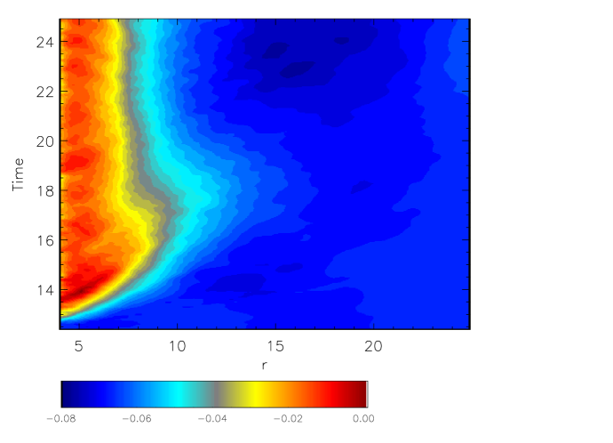
If orbiting material moved as independent test-particles, the inner rings would precess much faster than the outer rings because the precession frequency declines outward . To measure the actual precession, we define the precession angle , where are the shell-integrated and components of the angular momentum relative to a coordinate system found by rotating the grid coordinates around the axis in order to make the black hole spin define the axis. As Figure 2 shows, although the inner rings do precess faster, the radial gradient is noticeably shallower than : after 1 orbit, although a test-particle at would have precessed by , the actual fluid ring at that radius has precessed by only , while the ring at has precessed by an amount similar to the test-particle prediction; after 3 orbits, precession is ill-defined at because that portion of the disk has already almost completely aligned, but the difference in precession angle between and is only , in contrast to the test-particle expectation of .
Several other features in this diagram are even more contrary to test-particle expectations. Most importantly, the precession angle hardly changes from onward for . Also beginning at , or after only orbits of torque, a zone at larger radius, , reverses its sense of precession for several orbits. Once the sense of precession at large radius resumes its normal sense (at ), the precession phase gradient becomes very shallow throughout the disk.
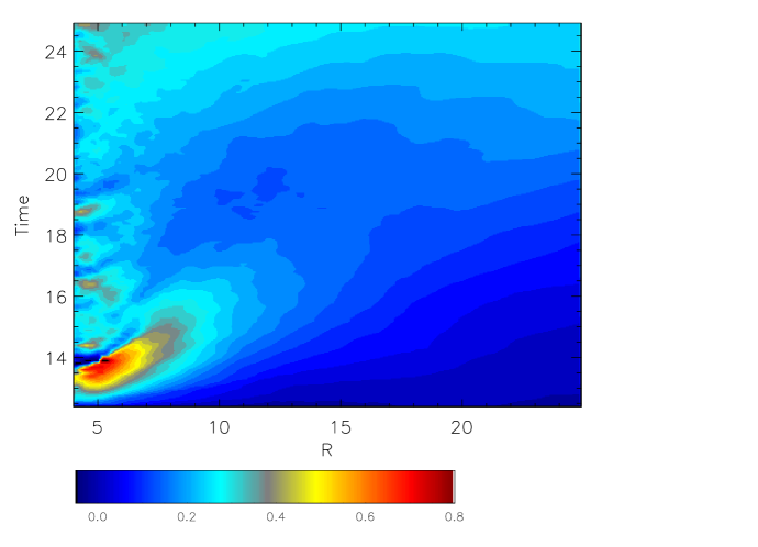
Meanwhile, the innermost disk aligns very swiftly, within a few fiducial orbits. The location of the alignment front moves rapidly outward, with the half-alignment point reaching only fiducial orbits after the torques begin. However, there is a turn-around in the process and the front retreats over the next several orbits until it reaches its steady-state position at –8. From until the end of the simulation at , neither the position nor the structure of the front changes appreciably.
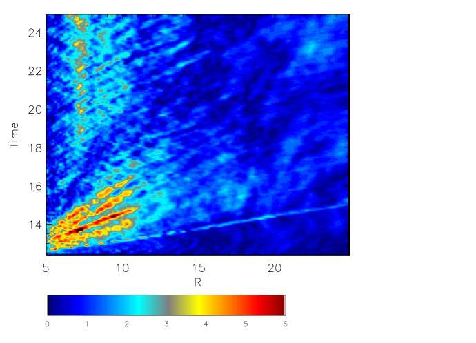
Even though the disk remains near its original alignment at after , it continues to precess slowly at large radii, turning at a rate radians per fiducial orbit, roughly the test-particle precession rate at . Although there is little torque inside the alignment radius (), there is sufficient obliquity at larger radii that the disk continues to feel a torque. This torque is spread to larger radii by the same mechanisms seen in earlier studies (Sorathia et al., 2013b, a). When the radial precession gradient creates an inter-ring warp of nonlinear amplitude, it triggers a warp pulse that travels outward. Nonlinear in this context means that the parameter , where is the unit vector in the direction of the total angular momentum associated with the shell at radius . When that criterion is satisfied, the warp creates an order-unity radial pressure contrast. The resulting transonic fluid motions mix angular momentum between rings, smoothing the warp. This same smoothing process keeps the pulses narrow. Two groups of such pulses can be clearly seen in Figure 4. During the first orbits, five pulses of strong (–6) warp propagate outward. Although each one travels at very nearly constant speed, the pulse speed declines from first to last, falling from to , i.e., from to , from first pulse to last. Their direct impact on local precession angle can be seen immediately by comparing Figures 2 and 4. A second group, somewhat weaker (–3), are visible in the zone and . Although less dramatic, their effect on precession phase can likewise be seen by examination of the region in radius–time space occupied by these pulses in Figure 2. All of this group of pulses have rather similar speeds, length units per fiducial orbital period, . As hinted by this speed, these pulses are related to linear bending waves, whose characteristic propagation speed is half the isothermal sound speed (Lubow et al., 2002). However, a number of factors combine to make their behavior somewhat different. In addition to the rapid local damping caused by their nonlinearity, Figure 4 also shows that their amplitude is quite irregular, a symptom of their propagation through a background medium made turbulent by the magneto-rotational instability (Sorathia et al., 2013a).
Throughout the evolution, the disk continues to accrete due to internal stresses, but in the vicinity of the alignment front, the radial motions induced by the disk warp create a large enough Reynolds stress to enhance the local inflow rate. To measure this effect, we compute the mean radial, i.e., accretion, velocity from the mass flux as follows:
| (6) |
This velocity is then averaged over time for the last orbit of the simulation. The result is shown in Figure 5 as the ratio of the accretion velocity to local orbital velocity. This ratio is well outside the transition front (), but its magnitude increases inward from that radius, becoming greater by , the location of the front. Another consequence of this effect is a shift in mass from the surface density peak, which is at –20 when the torque begins, to the transition front region (compare Figs. 6 and 1). Note that the diminution in radial speed at very large radius is an artifact common to any accretion simulation with a finite disk: matter on the outside must move still farther away as it absorbs angular momentum transported to larger radius by the accretion stresses.

Over the course of the evolution with torque, the quality parameters maintain values consistent with adequate resolution. Within the region of the disk running from –20, ranges from 9–14, while varies between 20 and 30.

4 Analysis
4.1 Overshoot
Because the torque is turned on abruptly, the disk is subject to some transient effects as it adjusts; one of these is an overshoot in the location of the alignment radius. This “overshoot”—the quick progress outward of the alignment front followed by a retreat to its long-term position—can be understood as a combination of several previously-identified processes.
The overshoot begins as the five strong warp pulses described in the previous section propagate outward. When the inner regions are advanced in precession phase relative to the outer regions, the gravitomagnetic torque delivered to the inner regions is directed so that it can partially cancel the misaligned angular momentum of the outer regions (Sorathia et al., 2013a). Accomplishing this cancellation requires transport outward, and the pulses do this. Alignment by this mechanism can be particularly rapid when there is little warp at still larger radii because radial mixing flows bringing inward angular momentum aligned with the original orientation of the disk are weak.
However, a consequence of quick alignment is the creation of significant warp. After roughly a local orbital time (and at the relevant radii near , the local orbital time is the same as our fiducial orbital period), the newly-created warp accelerates radial mixing flows (Sorathia et al., 2013b). The delay time is roughly a local orbital period because this is the local dynamical time. These radial flows carry inward angular momentum that is both more misaligned and further behind in precession phase. As a result, the local alignment is reduced and the precession temporarily reverses. Thus, both the alignment front overshoot and the precession reversal can be understood as consequences of transients associated with the beginning of torque in a flat, but misaligned, disk. Although it is somewhat artificial to turn on the Lense-Thirring torque abruptly, this procedure does allow us to highlight the dynamic alignment process as it subsequently occurs. The disk ultimately achieves a steady state alignment configuration, despite the impulsive initial nature of the torque.
4.2 Location of the steady-state orientation transition
The ultimate location of the alignment front is also very consistent with the formalism proposed by Sorathia et al. (2013a) to estimate both the propagation speed of an alignment front and the location where it stalls, reaching a steady-state. They proposed that the alignment front should move outward at a rate
| (7) |
where is the mean angle between the angular momentum being mixed outward and the local misaligned angular momentum, and is the local misalignment angle. Testing this model against their simulation data, they found excellent agreement. The expression for the front speed can also be rewritten in an entirely equivalent form, in which the integration variable is transformed to the dimensionless :
| (8) |
In other words, the characteristic speed of the alignment front is .
Sorathia et al. (2013a) suggested that the place where the front should stall is defined by the place at which the speed of the alignment front is matched by the speed with which misaligned angular momentum from the outer disk can be mixed inward. From their simulation data, it was impossible to estimate the speed of inward mixing. However, they proposed a simple parameterization for describing it, in which the speed of misaligned angular momentum flow was taken to be . In this language, the steady-state orientation transition would be found at , defined by
| (9) |
where is the dimensionless integral in equation 8.
Our simulation data give the location of , so equation 9 can be inverted to find the characteristic inflow time for misaligned angular momentum:
| (10) |
Taking , we find that during the period , when the alignment front appears to be almost constant in position, fiducial orbits, the exact value varying slightly from time to time. As a standard of comparison, we note that the orbital period at is fiducial orbits.
One possible interpretation of this mixing time is in terms of a diffusion model (Papaloizou & Pringle, 1983; Pringle, 1992), although Sorathia et al. (2013b) showed that this is not a perfect match with actual time-dependent response to disk warping. However, even if it does not describe time-dependent effects, a diffusion model might be an appropriate device with which to model the radial angular momentum mixing supporting a time-steady alignment front. If one does describe the mixing as a diffusion process, the associated diffusion coefficient should be because the characteristic speed of radial flows (Sorathia et al., 2013b), and orbital mechanics limits the distance such a flow can travel radially to . Although disk warp does create radial pressure gradients of the sort envisioned by Papaloizou & Pringle (1983), the associated radial velocities are not regulated by an “isotropic viscosity” (Sorathia et al., 2013a; Morales Teixeira et al., 2014), but by hydrodynamic expansion, gravity, and weak shocks (Sorathia et al., 2013b). The characteristic speed of mixing is then , where is the characteristic lengthscale for orientation change within the front, and is a number of order unity that can be determined from simulations like ours. Defining for the difference in direction between the disk’s initial orientation and its aligned direction, we find . Equating this speed to the unimpeded leads to an estimate for the stationary front location
| (11) |
In order to find a scale for , we have created units relative to a fiducial radial scale . Note that in terms of the formalism created by Nelson & Papaloizou (2000), this expression corresponds approximately to the geometric mean of and .
If this model correctly describes the dynamics of alignment front equilibrium, the order unity quantity is
| (12) |
Our data indicate that –0.8, depending on the time at which it is measured.
It is possible that might be independent of other parameters; however, that remains to be demonstrated. It could be, for example, that is dependent on . It should also be noted that because the width of the orientation transition was smaller than the disk simulated, the transition thickness and the internal warp rate were free to adjust to whatever the dynamics required. There may be cases in which the intrinsic disk obliquity is large enough, and the radius at which the disk is fed is small enough, that additional constraints are placed on and therefore ; these might then also alter . In extreme cases, shock heating might be strong enough to alter , leading to nonlinearity in the effective diffusion rate.
4.3 What is the role of bending waves?
As discussed in Sec. 3.2, we see clear evidence for nonlinear bending wave pulses moving through the aligning disk. However, these pulses propagate in a rather irregular way, their amplitudes fluctuating strongly as they move outward through the disk. In our previous paper (Sorathia et al., 2013a), we showed that in a purely hydrodynamic situation these pulses propagate much more regularly. We attributed the contrast to the fact that warped hydrodynamic disks are laminar, whereas warped MHD disks are turbulent; the turbulence disrupts, but does entirely destroy, these waves. One consequence (as seen both in the previous simulation and in this one) is that an MHD disk is not able to maintain a state of solid-body rotation, which it does achieve in a purely hydrodynamic state (Sorathia et al., 2013a).
Since the work of Papaloizou & Pringle (1983), it has been customary to categorize the dynamics of warped disks in terms of a division between a “bending wave” regime, in which the ratio of vertically-integrated accretion stress to vertically-integrated pressure is , and a “diffusive” regime, in which . It might then seem a natural question to ask how the phenomena we observe may be classified in these terms. Before doing so, however, it is useful to recall the origin of this distinction. It was derived by assuming that linear bending waves damp at a rate , while the speeds of the radial motions induced by the warp-created radial pressure gradients are controlled by an “isotropic viscosity” acting to reduce vertical shear. “Isotropic” meant that if the vertical shear were the same as the orbital shear, the - component of the stress would be the same as the accretion stress, the - component.
However, neither of these assumptions fits well with the conditions in warped MHD disks. In the vicinity of an alignment front, the warp is almost always nonlinear in the sense that because even the transonic radial motions induced by nonlinear warps cannot spread the front enough to make it linear. This condition is generic because the location of the front is determined by the condition that the mixing timescale is comparable to the precession timescale. Indeed, the only regions in our simulation in which the warp is linear are at sufficiently large radius that they are essentially untouched by the torques. Consequently, the relevant damping rate is the one applicable to nonlinear waves. As shown in Sorathia et al. (2013b), damping of nonlinear warps takes place very rapidly, and the mechanism is exactly what is commonly associated with the “diffusive” regime: radial motions driven by the radial pressure gradients associated with the warp mix differently-aligned angular momentum across a radial orientation gradient. Thus, nonlinear bending waves combine aspects of these two, nominally contrasting, regimes.
In addition, as shown in Sorathia et al. (2013a) and Morales Teixeira et al. (2014), there is no “isotropic viscosity”. The - component of the Maxwell stress does not behave like a viscosity: it is as likely to strengthen shear as to weaken it. Moreover, its magnitude, when measured in pressure units, is typically three orders of magnitude smaller than the stress associated with accretion. Consequently, the speeds of the radial motions are limited not by a “viscosity”, but, when the warp is nonlinear, by the dynamics of free expansion in the presence of gravity and by weak shocks that occur when the radial motions encounter other parts of the warped disk. For this reason, the radial speeds in regions of nonlinear warp are in general transonic, with Mach numbers that increase with greater (Sorathia et al., 2013b). Thus, it is questionable whether the “bending wave” vs. “diffusive” distinction can be applied here; the only distinction having the potential to be qualitative is between linear and nonlinear bending waves.
4.4 Do warped disks break?
When disks subjected to Lense-Thirring torques are simulated in pure hydrodynamics with an assumed isotropic viscosity and using the SPH algorithm, under certain circumstances breaks have appeared between the outer misaligned section and the inner aligned portion (Nixon & King, 2012; Nixon et al., 2012; Nealon et al., 2015). One proposed criterion for this to happen is that the external torque exceed the inter-ring torque associated with accretion stresses (Nixon et al., 2012; Nealon et al., 2015). Alternatively, it may be that the criterion is for the precession timescale to be shorter than the radial sound-crossing timescale (Nealon et al., 2015).
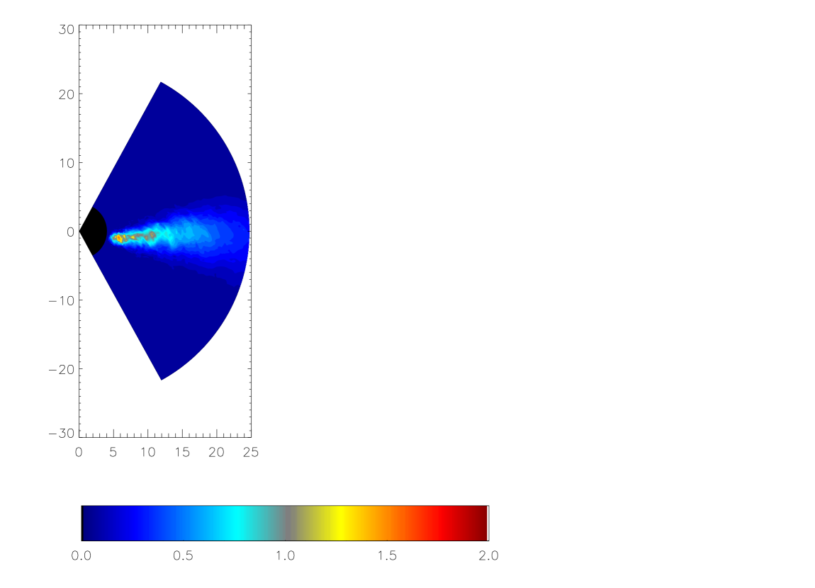
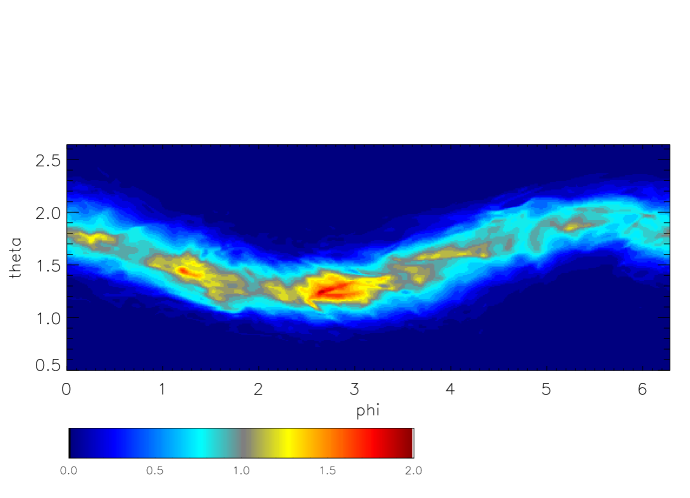
We use several diagnostics to test our late-time data for disk breaks in this simulation. The first is continuity in the azimuthally-averaged surface density. As can readily be seen in Figure 6, varies quite smoothly with radius. Indeed, the surface density near the alignment transition hardly changes over the fiducial orbits in which the torques operate, while the surface density at somewhat larger radii increases. Another is the density distribution in the poloidal plane measured at the azimuth corresponding to the outer disk precession angle. This is shown in Figure 7. The plane of the disk does vary, of course. At small radii, where it is aligned normal to the black hole spin, it is tilted by with respect to the grid; at large radii, precession around the black hole spin direction moves it out of the equatorial plane. Throughout the radial extent of the disk, the density distribution is lumpy, but the maximum contrast in density within the midplane is only about a factor of 2. Thus, this view also provides no evidence of breaks. A third diagnostic is the density distribution on a spherical shell at the radius where the warp is greatest (Fig. 8). Because the mean angular momentum on this shell is tilted by a bit more than half the initial inclination relative to the coordinate equatorial plane, and it has precessed, the disk plane traces a sinusoidal pattern in polar angle relative to the plane in this coordinate system. It shows density fluctuations at the factor of 3 level, but there is also no indication of a dramatic break here either, even though this is the radius where is greatest (see Fig. 4).
It is therefore instructive to test whether the proposed break criteria apply to a calculation in which all stresses are physical and numerical transport can be readily controlled. The first criterion can be concisely phrased if the actual accretion stress is measured in pressure units, i.e., in terms of , the time-averaged ratio of vertically-integrated stress to vertically-integrated pressure. It is then
| (13) |
At the location of the orientation transition (), the frequency ratio is , while our measured stress ratio declines with radius from at to at . Combined with our disk aspect ratio and the outer disk inclination , we find . Thus, even though the precessional torque is considerably greater than the inter-ring accretion torque, the disk does not break.
One possible explanation for this discrepancy is that the argument for the criterion assumes that ordinary accretion stresses are responsible for restoring matter to regions in which the precessional stress might otherwise create gaps. However, warped disks induce strong Reynolds stresses, and these can easily be much stronger than the Maxwell stresses due to correlated MHD turbulence that ordinarily drive accretion. In fact, at a steady-state alignment transition front, these Reynolds stresses produce a torque that is—by definition—equal to the aligning torque at the front, and the aligning torque is comparable to the full Lense-Thirring precessional torque. Thus, if the correct criterion for producing a break is for the Lense-Thirring torques to exceed the smoothing torque due to internal stresses, there could never be a strong break at a disk’s most vulnerable point, the alignment transition.
The second criterion amounts to computing the product
| (14) |
where is the time for sound waves to traverse a distance comparable to the radius where this product is measured. If the theory for the location of the transition radius outlined in the previous section is correct, this criterion may be rewritten as
| (15) |
Thus, this ratio is always . For our simulation’s parameters, it is at the alignment transition. Just as for the previous criterion, our theory predicts that this criterion, too, should always be marginal, and therefore strong breaks would not be expected.
Nealon et al. (2015) suggest that this criterion applies in what they deem the “bending wave” regime, a regime in which the pressure-coupling of bending waves provides the strongest coupling between adjacent rings. Because these waves generically travel at , the sound wave crossing time is a reasonable estimate of their crossing time also. As we have already argued, linear bending waves do not appear to be particularly important contributors to tilted disk dynamics. However, nonlinear warps result in transonic flows, whose effects also travel at . In this sense, it is not surprising that we would predict that this criterion, like our reworked version of the first, should also always be marginal at the orientation transition radius.
4.5 Is apsidal precession relevant?
It has been argued in a number of places (Ivanov & Illarionov, 1997; Morales Teixeira et al., 2014; Nealon et al., 2015) that apsidal precession can lead to radial alignment oscillations, perhaps affecting overall disk alignment. Nonetheless, in our lowest-order PN accounting of general relativistic effects, we have included the gravitomagnetic term, but not the term associated with apsidal precession, even though the two effects are formally the same order in the expansion. We did so for a number of reasons. One reason is that there is no way to make the apsidal precession consistent with the magnitude of our amplified gravitomagnetic term. However, we also believe it to have at most minor physical influence. Several arguments point in this direction. First, the amplitude of the velocity perturbations created by this effect is very small. They are proportional to the eccentricity of the orbits, and . As a result, the Mach number of these motions is only of order the ratio of the gravitational radius to the radius, which is generally quite small for . They are then far slower than the transonic radial motions themselves; in fact, they are very small even compared to the fluid motions associated with the turbulence, which are . Second, the radial flows are altered by hydrodynamics on the orbital period, as streams encounter other portions of the disk, sometimes through shocks. By contrast, during one orbital period, the magnitude of the apsidal precession angle is only for . Thus, during the time over which a specific elliptical orbit exists, it is rotated by only a very small amount, while that fluid’s motions are changed at the order-unity level by other mechanisms. Third, the apsidal precession can also be viewed as due to a small offset between the frequency of radial epicyclic motions and the orbital frequency. However, in an MHD orbiting fluid, the magnetorotational instability makes radial epicyclic motions unstable, and the fastest growing mode has a growth rate . It is hard to see how the apsidal precession would be significant relative to all these other effects.
5 Conclusions
Our simulation has shown that an accretion disk whose intrinsic orbital plane is inclined obliquely to the equatorial plane of the central spinning black hole can achieve a steady-state in which the inner disk aligns with the black hole’s equatorial plane while the outer disk retains its original orientation.
Using the alignment front propagation formalism developed in a previous paper (Sorathia et al., 2013a), we have, for the first time, measured directly the timescale for misaligned angular momentum mixing due to the radial flows induced by disk warping. In this specific case, that time scale is local orbital periods. In the context of a time-steady alignment front, it is possible to estimate this mixing timescale in terms of a diffusion model of the sort first explored by Papaloizou & Pringle (1983) and Pringle (1992). Because nonlinear warps generically produce transonic radial motions, one would expect the diffusion coefficient in such a model to be , where is a dimensionless number of order unity. Interpreting the mixing time we measure in terms of such a model, one would then expect for fractional front width . Calibrating this relation with our simulation data, we find that –0.8 for our measured fractional front width . Finding a coefficient of order unity is consistent with the thought that a diffusion model of this character may be appropriate to estimating the equilibrium properties of disk warps, even though this model is inadequate to describe their time-dependent properties. Stronger evidence for this proposition must await simulations with different values of the sound speed to orbital speed ratio and perhaps also different disk inclination angles; it remains possible that could depend on these, or other, parameters.
Nonetheless, if this estimate is good to factors of several, it permits estimation of steady-state orientation transition radii, given the black hole mass and spin and the accretion disk surface density and aspect ratio profiles. In fact, this approach has already been taken by Miller & Krolik (2013), who assumed ; the results of our new simulation support their assumption.
We have also probed several quantitative aspects of the alignment front’s approach to equilibrium. For example, we observed an overshoot in the front’s location before settling into a steady-state. A pure diffusion picture of warp motion would not yield this sort of behavior, but its qualitative character (in particular, its relaxation time) is consistent with previous detailed studies of warped disk hydrodynamics (Sorathia et al., 2013b). We have also begun to constrain suggestions that disks undergoing Lense-Thirring torques can suffer sharp breaks (Nixon & King, 2012; Nixon et al., 2012). Nealon et al. (2015) offered criteria for when these breaks should develop; despite satisfying one of their criteria strongly and another one marginally, we find no evidence for this happening. If their primary criterion were reframed to include the effects of the radial motions induced by a strong warp, we would find both are marginal, and for the same reason: at a steady-state alignment front, the torque due to the Reynolds stress of these motions is automatically matched to the torque applied by gravitomagnetism, thereby creating a relatively rapid change in disk plane orientation across the front, but not a sharp break.
A number of questions remain open for future work. Among the most interesting are the degree to which may vary with parameters such as and the possible effect of boundary conditions that prevent the transition front from extending across as wide a radial range as internal dynamics would demand. If the location of disk-feeding is at a relatively small radius and the total change in angle across the alignment front is relatively large, the warp rate may be forced to become larger than it would be otherwise. In such a situation, there might be both a significant alteration in and enough shock heating to create nonlinearity through thermodynamic effects.
Acknowledgements
We thank John Papaloizou for enlightening and encouraging conversations. This work was partially supported under National Science Foundation grants AST-1028111 (JHK) and AST-0908869 (JFH), and NASA grant NNX14AB43G (JHK and JFH). The National Science Foundation also supported this research in part through XSEDE resources on the Stampede cluster through allocation TG-MCA95C003.
References
- Balbus & Hawley (1991) Balbus, S. A., & Hawley, J. F. 1991, Astrophysical Journal, 376, 214
- Balbus & Hawley (1998) —. 1998, Reviews of Modern Physics, 70, 1
- Bardeen & Petterson (1975) Bardeen, J. M., & Petterson, J. A. 1975, ApJL, 195, L65
- Fragile et al. (2007) Fragile, P. C., Blaes, O. M., Anninos, P., & Salmonson, J. D. 2007, ApJ, 668, 417
- Hawley et al. (2011) Hawley, J. F., Guan, X., & Krolik, J. H. 2011, ApJ, 738, 84
- Hawley et al. (2013) Hawley, J. F., Richers, S. A., Guan, X., & Krolik, J. H. 2013, ApJ, 772, 102
- Hawley & Stone (1995) Hawley, J. F., & Stone, J. M. 1995, Computer Physics Communications, 89, 127
- Ivanov & Illarionov (1997) Ivanov, P. B., & Illarionov, A. F. 1997, MNRAS, 285, 394
- Lubow et al. (2002) Lubow, S. H., Ogilvie, G. I., & Pringle, J. E. 2002, MNRAS, 337, 706
- McKinney et al. (2013) McKinney, J. C., Tchekhovskoy, A., & Blandford, R. D. 2013, Science, 339, 49
- Miller & Krolik (2013) Miller, M. C., & Krolik, J. H. 2013, ApJ, 774, 43
- Morales Teixeira et al. (2014) Morales Teixeira, D., Fragile, P. C., Zhuravlev, V. V., & Ivanov, P. B. 2014, ApJ, 796, 103
- Nealon et al. (2015) Nealon, R., Price, D., & Nixon, C. 2015, ArXiv e-prints
- Nelson & Papaloizou (2000) Nelson, R. P., & Papaloizou, J. C. B. 2000, MNRAS, 315, 570
- Nixon (2015) Nixon, C. 2015, ArXiv e-prints
- Nixon et al. (2012) Nixon, C., King, A., Price, D., & Frank, J. 2012, ApJL, 757, L24
- Nixon & King (2012) Nixon, C. J., & King, A. R. 2012, MNRAS, 421, 1201
- Noble et al. (2010) Noble, S. C., Krolik, J. H., & Hawley, J. F. 2010, The Astrophysical Journal, 711, 959
- Ogilvie (1999) Ogilvie, G. I. 1999, MNRAS, 304, 557
- Papaloizou & Pringle (1983) Papaloizou, J. C. B., & Pringle, J. E. 1983, MNRAS, 202, 1181
- Pringle (1992) Pringle, J. E. 1992, MNRAS, 258, 811
- Shi et al. (2012) Shi, J.-M., Krolik, J. H., Lubow, S. H., & Hawley, J. F. 2012, ApJ, 749, 118
- Sorathia et al. (2013a) Sorathia, K. A., Krolik, J. H., & Hawley, J. F. 2013a, ApJ, 777, 21
- Sorathia et al. (2013b) —. 2013b, ApJ, 768, 133
- Sorathia et al. (2012) Sorathia, K. A., Reynolds, C. S., Stone, J. M., & Beckwith, K. 2012, ApJ, 749, 189
- Stone & Norman (1992a) Stone, J. M., & Norman, M. L. 1992a, The Astrophysical Journal Supplement Series, 80, 753
- Stone & Norman (1992b) —. 1992b, Astrophysical Journal Supplement v.80, 80, 791