Probing the magnetic moment of FePt micromagnets prepared by Focused Ion Beam milling
Abstract
We investigate the degradation of the magnetic moment of a 300 nm thick FePt film induced by Focused Ion Beam (FIB) milling. A rod is milled out of a film by a FIB process and is attached to a cantilever by electron beam induced deposition. Its magnetic moment is determined by frequency-shift cantilever magnetometry. We find that the magnetic moment of the rod is , which implies that 70 % of the magnetic moment is preserved during the FIB milling process. This result has important implications for atom trapping and magnetic resonance force microscopy (MRFM), that are addressed in this paper.
The fabrication and characterization of micron sized permanent magnets is necessary for a broad range of applications, such as magnetic tweezers,Crick, F.H.C. and Hughes (1950); Smith, Finzi, and Bustamante (1992) magnetic imaging,Sidles (1991); Longenecker et al. (2012) and atom trapping with chips.Sidorov, McLean, and Sexton (2001)
These chips are planar structures that generate magnetic fields, which are widely used to control ultra-cold atoms.Whitlock et al. (2009) The incorporation of permanent magnets in atom chips offers several advantages over the use of current carrying wires:Sidorov, McLean, and Sexton (2001); Davis (1999) they dissipate no heat and allow more complex trap shapes. Moreover, permanent magnets can create larger field gradients, which facilitates tighter confinement of atoms,Xing et al. (2004) resulting in shorter time scales in trapping experiments. This does require the magnets to be patterned on small length scales. One of the materials currently under investigation is FePt in its L10 phase, a corrosion resistant material with high magnetocrystalline anisotropy.Xing et al. (2004, 2007); Gerritsma et al. (2007) FePt atom traps that are currently in use are made by optical lithography and plasma etching.Gerritsma et al. (2007); Leung et al. (2014) The currently used patterns have length scales on the order of 10 m.Jose et al. (2014)
Micron sized magnets can also be used as a field gradient source for magnetic resonance force microscopy (MRFM).Sidles (1991) This is a technique that uses a small magnet mounted on an ultrasoft cantilever to measure the magnetic interaction with spins in a sample underneath the cantilever. It thereby combines the advantage of elemental specificity of conventional Magnetic Resonance Imaging (MRI) techniques with the local and very sensitive probing techniques of Atomic Force Microscopy (AFM).Degen et al. (2009); *Poggio2010 Required properties for MRFM magnets are high magnetocrystalline anisotropy and a large remanent field.Stipe et al. (2001) Small dimensions of the magnet are beneficial too, as they result in large magnetic field gradients, which increase the sensitivity of measurements.Jenkins and DeFlores (2004); *Poggio2007 These requirements are similar to the requirements for atom traps and are all fulfilled by the aforementioned FePt.
One of the techniques to pattern FePt films is to use a Focused Ion Beam (FIB). However, FIB milling can damage the film, possibly degrading the magnetic properties. Examples of such damage include implantation of ions and other ion beam induced alterations to the crystal structure.Rubanov and Munroe (2004); *Giannuzzi1999 Determining the magnetic moment after FIB exposure is crucial for applications in both atom trapping and MRFM experiments.
In this letter, the damage caused by FIB milling on an FePt film is quantified by measuring the magnetic moment of a micron sized rod, which has been milled out of the film, and comparing it to the expected magnetic moment calculated from its volume and its remanent field. The rod is attached to a cantilever and its magnetic moment is determined by cantilever magnetometry, a sensitive technique to determine small magnetic moments.Stipe et al. (2001); *Rossel1996 We demonstrate that FIB milling is a suitable way to shape magnetic films for atom trapping experiments and to prepare probes for MRFM.
The thick FePt film has been made at the Almaden Research Center of Hitachi. Films of FePt have been sputtered on a Si substrate with a thin RuAl underlayer and a Pt interlayer at a temperature of . This growth process leads to FePt in its L10 phase, which has a particularly high out-of-plane magnetization. Shen, Judy, and Wang (2005)
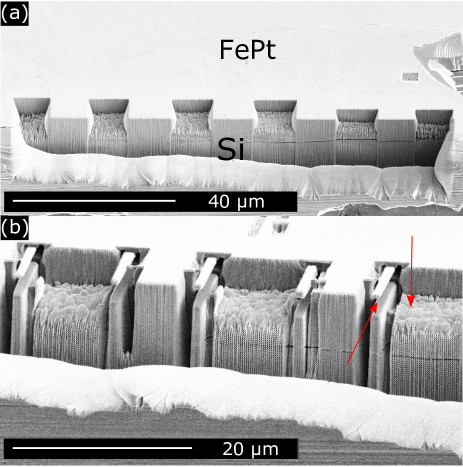
As a first step to create rods, an indentation in the edge of the film is made with a FIB (Ga+-ions, 30 keV, 7 nA ion current, Strata 235 Dual Beam from FEI). The edge is then crenelated (Fig. 1(a)) (ion current 500 pA) and rods are created in the sides of the crenels (Fig. 1(b)). The dimension of the rods is 8.1 m in length, 1 m in width and 1 m in height (consisting of 300 nm FePt and 700 nm substrate). The sample is rotated by 90∘ to remove the material underneath the rods. The geometry facilitates the access necessary to mount a rod onto a cantilever.
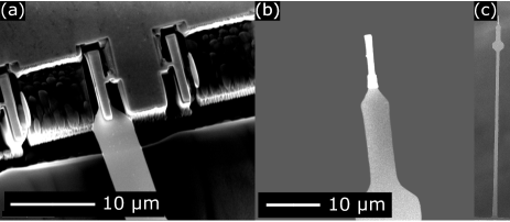
The FePt film and a cantilever (a single-crystalline silicon beam B. Chui, Y.Hishinuma, R. Budakian, H. Mamin, T. Kenny (2003)) are then placed on two stages of an in-house developed nanomanipulator Heeres et al. (2010) inside a Scanning Electron Microscope (NanoSEM 200 from FEI, USA). Using the nanomanipulator, we bring the cantilever in contact with an FePt rod (Fig. 2(a)). Subsequently, fixation is achieved by an electron beam induced deposition process with Pt(PF3)4 as a precursor gas. The last connection between the rod and the film is broken by suddenly retracting the cantilever. The finished assembly of the cantilever and the rod is shown in Fig. 2(b) and 2(c).
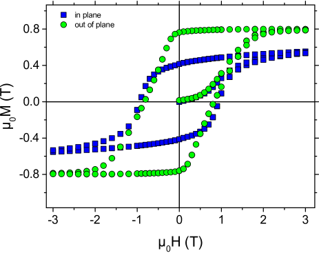
Prior to the fabrication of the rods, the magnetization loop has been measured for a film of size 3 mm x 3 mm x 300 nm in a SQUID magnetometer (Quantum Design MPMS-5S). The measurement has been performed at room tempeature in two different geometries (Fig. 3): with an in-plane and an out-of-plane external field H. The remanent magnetization is for the out-of-plane geometry, while it is for the in-plane geometry. In Fig. 3, the remanant magnetic moment shows negligible dependence on the external magnetic field. This is expected for FePt, as the coercivity increases when the lateral size decreases.Attané et al. (2011) Therefore, the external field used in the cantilever magnetometry experiment should not affect the magnetic moment of the rod.
The rods are magnetized in a 3 T field at room temperature along the out-of-plane direction (i.e. along the direction of motion of the cantilever), to achieve a higher remanent field.
Subsequently, dynamic-mode cantilever magnetometry is performed at room temperature at a pressure of 10-5 mbar. The external magnetic field is provided by a Helmholtz coil of approximately 300 turns, generating magnetic fields up to 2 mT. The external magnetic field points along the direction of motion of the cantilever. To determine the magnetic moment of the rod, the resonance frequency is measured as a function of magnetic field strength. A fiber optic interferometer working at a wavelength of 1550 nm is used to detect the cantilever motion. The resonance frequency is determined by fitting the thermal motion of the cantilever’s fundamental mode to a Lorentzian curve. A ring-down measurement, shown in Fig. 4(b), provides a more accurate measure of the quality factor Q.
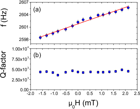
The resonance frequency as a function of magnetic field is shown in Fig. 4(a). For the low magnetic field regime, the frequency shift as a function of magnetic field H is given by:Marohn, Fainchtein, and Smith (1998)
| (1) |
where is the resonance frequency in the absence of a magnetic field, is the length of the cantilever, is a constant factor derived for beam cantilevers, and is the stiffness of the cantilever, determined by the ‘added-mass method’. Cleveland et al. (1993)
Making use of equation 1, the magnetic moment of the cantilever is deduced to be . Given the remanent magnetization of the FePt film and the volume of the magnet of , we would have expected a magnetic moment of , if the magnet had been unaffected by the FIB process. The comparison shows that roughly 60 to 80 % of the magnetic moment is preserved during the FIB process. As both SQUID magnetometry and cantilever magnetometry allow only for the determination of the overall magnetic moment, we cannot precisely determine the damage profile.
The quality factor seems not to depend on the magnetic field strength. Ng et al.Ng, Jenkins, and Marohn (2006) did report on a decrease of the quality factor in a magnetic field ranging up to 6 T. This change is negligible in the 2 mT magnetic field range we studied.
More FePt magnets have been attached to cantilevers by the procedure described above. However, the orientation of the out-of-plane direction of the FePt film with respect to the direction of motion of these cantilevers was different (see supplemental materialsub for more information). Though beneficial for MRFM experiments,Marohn, Fainchtein, and Smith (1998) these probes are unfit for cantilever magnetometry experiments.
We believe MRFM would benefit from the described force sensor. Since the force exerted by a spin in the sample on the cantilever is proportional to the gradient of the magnetic field, it is beneficial to use small magnets. In our previous work, we employed NdFeB spheres with a diameter of 3 m. Vinante et al. (2012) The field gradient cannot be increased by using smaller NdFeB particles, because they seem to lose their magnetization when scaled down further. Hammel Even though FePt has a remanant magnetization which is roughly half as large as that of NdFeB, the possibility to create smaller magnets is promising for the sensitivity of MRFM experiments. The larger magnetic field gradient is not the only improvement that small FePt magnets would yield. It has been observed that the quality factor of MRFM cantilevers can drop drastically when approaching the sample surface.Vinante, Wijts, and Usenko (2011) This is most likely due to a dissipative interaction of spins in the sample with the magnet. A smaller magnet interacts with fewer spins and therefore suffers less from this unwanted damping. A forthcoming experiment will enable us to quantify the improvement in the resolution provided by the FePt rods.
Concerning atom trapping, the factor limiting the resolution of FePt traps created by optical lithography and plasma etching is the redeposition of the etched material, the magnetic properties of which are unknown.Gerritsma (2007) SEM images show that this redeposition can be of the order of several hundreds of nanometers. From SEM images made after FIB milling, we conclude that for the FePt rods described in this paper redeposition of FePt is negligble compared to the loss of magnetic volume caused by the FIB milling process. Furthermore, the damage induced can possibly be reduced by using a helium FIB. Hence FIB milled patterns could have an advantage over patterns created by optical lithography and plasma etching, when aiming for trap sizes on the order of a micrometer.Leung et al. (2011); Herrera et al. (2014) For the formation of such traps a better understanding of the shape of the damaged region of magnetic films would be needed. FIB milling of FePt will probably not suffice to go to an atom trap scale of the order of 100 nm. Electron beam lithography is the most suitable technique when aiming for submicrometer sizes. Leung et al. (2011) This method is currently used in various groups.
We have shown a fabrication process for micrometer size FePt magnets by FIB milling and a way to attach these magnets to ultrasoft cantilevers by electron beam induced deposition. This technique could in principle be used for any magnetic film. From cantilever magnetometry measurements we conclude that 60 to 80 % of the magnetic moment is preserved during the FIB milling process. FIB milled magnets could therefore be used in atomic trapping experiments when aiming for a trap size on the order of a micrometer. The magnet attached to the cantilever can be used as a probe in MRFM experiments. The small dimensions of the magnet are expected to improve the sensitivity of MRFM.
Acknowledgements.
The authors thank J.J.T. Wagenaar for fruitful discussions. This work was supported in part by Fundamenteel Onderzoek der Materie (FOM) and by the Netherlands organization of scientific research (NWO).References
- Crick, F.H.C. and Hughes (1950) Crick, F.H.C. and A. Hughes, Exp. Cell Res. 1, 37 (1950).
- Smith, Finzi, and Bustamante (1992) S. B. Smith, L. Finzi, and C. Bustamante, Science 258, 1122 (1992).
- Sidles (1991) J. A. Sidles, Applied Physics Letters 58, 2854 (1991).
- Longenecker et al. (2012) J. G. Longenecker, H. J. Mamin, A. W. Senko, L. Chen, C. T. Rettner, D. Rugar, and J. A. Marohn, ACS Nano 6, 9637 (2012).
- Sidorov, McLean, and Sexton (2001) A. Sidorov, R. McLean, B. Sexton, D. Gough, T. Davis, A. Akulshin, G. Opat, and P. Hannaford, Comptes Rendus de l’Académie des Sciences - Series IV 2, 565 (2001).
- Whitlock et al. (2009) S. Whitlock, R. Gerritsma, T. Fernholz, and R. J. C. Spreeuw, New Journal of Physics 11, 023021 (2009).
- Davis (1999) T. Davis, Journal of Optics B: Quantum and Semiclassical Optics 1, 408 (1999).
- Xing et al. (2004) Y. T. Xing, A. Eljaouhari, I. Barb, R. Gerritsma, R. J. C. Spreeuw, and J. B. Goedkoop, Physica Status Solidi (C) 1, 3702 (2004).
- Xing et al. (2007) Y. Xing, I. Barb, R. Gerritsma, R. Spreeuw, H. Luigjes, Q. Xiao, C. Rétif, and J. Goedkoop, Journal of Magnetism and Magnetic Materials 313, 192 (2007).
- Gerritsma et al. (2007) R. Gerritsma, S. Whitlock, T. Fernholz, H. Schlatter, J. Luigjes, J.-U. Thiele, J. Goedkoop, and R. Spreeuw, Physical Review A 76, 033408 (2007).
- Leung et al. (2014) V. Y. F. Leung, D. R. M. Pijn, H. Schlatter, L. Torralbo-Campo, A. L. La Rooij, G. B. Mulder, J. Naber, M. L. Soudijn, A. Tauschinsky, C. Abarbanel, B. Hadad, E. Golan, R. Folman, and R. J. C. Spreeuw, The Review of scientific instruments 85, 053102 (2014).
- Jose et al. (2014) S. Jose, P. Surendran, Y. Wang, I. Herrera, L. Krzemien, S. Whitlock, R. McLean, A. Sidorov, and P. Hannaford, Physical Review A - Atomic, Molecular, and Optical Physics 89, 051602 (2014).
- Degen et al. (2009) C. L. Degen, M. Poggio, H. J. Mamin, C. T. Rettner, and D. Rugar, Proceedings of the National Academy of Sciences of the United States of America 106, 1313 (2009).
- Poggio and Degen (2010) M. Poggio and C. L. Degen, Nanotechnology 21, 342001 (2010).
- Stipe et al. (2001) B. Stipe, H. Mamin, T. Stowe, T. Kenny, and D. Rugar, Physical Review Letters 86, 2874 (2001).
- Jenkins and DeFlores (2004) N. Jenkins and L. DeFlores, Journal of Vacuum Science and Technology B 22, 909 (2004).
- Poggio et al. (2007) M. Poggio, C. L. Degen, C. T. Rettner, H. J. Mamin, and D. Rugar, Applied Physics Letters 90, 263111 (2007).
- Rubanov and Munroe (2004) S. Rubanov and P. R. Munroe, Journal of microscopy 214, 213 (2004).
- Giannuzzi and Stevie (1999) L. Giannuzzi and F. Stevie, Micron 30, 197 (1999).
- Rossel et al. (1996) C. Rossel, P. Bauer, D. Zech, J. Hofer, M. Willemin, and H. Keller, Journal of Applied Physics 79, 8166 (1996).
- Shen, Judy, and Wang (2005) W. K. Shen, J. H. Judy, and J.-P. Wang, Journal of Applied Physics 97, 10H301 (2005).
- B. Chui, Y.Hishinuma, R. Budakian, H. Mamin, T. Kenny (2003) D. R. B. Chui, Y.Hishinuma, R. Budakian, H. Mamin, T. Kenny, in Technical Digest 12th International Conference on Solid-State Sensors and Actuators (2003) pp. 1120–1123.
- Heeres et al. (2010) E. C. Heeres, A. J. Katan, M. H. van Es, a. F. Beker, M. Hesselberth, D. J. van der Zalm, and T. H. Oosterkamp, The Review of scientific instruments 81, 023704 (2010).
- Attané et al. (2011) J. P. Attané, D. Ravelosona, A. Marty, V. D. Nguyen, and L. Vila, Physical Review B - Condensed Matter and Materials Physics 84, 144418 (2011).
- Marohn, Fainchtein, and Smith (1998) J. A. Marohn, R. Fainchtein, and D. D. Smith, Applied Physics Letters 73, 3778 (1998).
- Cleveland et al. (1993) J. P. Cleveland, S. Manne, D. Bocek, and P. K. Hansma, Review of Scientific Instruments 64, 403 (1993).
- Ng, Jenkins, and Marohn (2006) T. N. Ng, N. Jenkins, and J. Marohn, IEEE Transactions on Magnetics 42, 378 (2006).
- (28) See supplemental material at http://dx.doi.org/10.1063/1.4928929 for a description of the different orientations in which magnets can be attached to cantilevers.
- Vinante et al. (2012) A. Vinante, A. Kirste, A. den Haan, O. Usenko, G. Wijts, E. Jeffrey, P. Sonin, D. Bouwmeester, and T. H. Oosterkamp, Applied Physics Letters 101, 123101 (2012).
- (30) P.C. Hammel, private communication, 2009.
- Vinante, Wijts, and Usenko (2011) A. Vinante, G. Wijts, and O. Usenko, Nature Communications 2, 572 (2011).
- Gerritsma (2007) R. Gerritsma, Permanent magnetic atom chips and Bose-Einstein condensation, Ph.D. thesis, Universiteit van Amsterdam (2007).
- Leung et al. (2011) V. Y. F. Leung, A. Tauschinsky, N. J. Druten, and R. J. C. Spreeuw, Quantum Information Processing 10, 955 (2011).
- Herrera et al. (2014) I. Herrera, Y. Wang, P. Michaux, D. Nissen, P. Surendran, S. Juodkazis, S. Whitlock, R. McLean, A. Sidorov, A. M., and P. Hannaford, J. Phys. D: Appl. Phys. 48, 115002 (2015).