EDM planning using ETEAPOT with a resurrected AGS Electron Analogue ring
Abstract
There has been much recent interest in directly measuring the electric dipole moments (EDM) of the proton and the electron, because of their possible importance in the present day observed matter/antimatter imbalance in the universe. Such a measurement will require storing a polarized beam of “frozen spin” particles, 15 MeV electrons or 230 MeV protons, in an all-electric storage ring. Only one such relativistic electric accelerator has ever been built—the 10 MeV “Electron Analogue” ring at Brookhaven National Laboratory in 1954; it can also be referred to as the “AGS Analogue” ring to make clear it was a prototype for the AGS proton ring under construction at that time at BNL. (Its purpose was to investigate nonlinear resonances as well as passage through “transition” with the newly-invented alternating gradient proton ring design.) By chance this electron ring, long since dismantled and its engineering drawings disappeared, would have been appropriate both for measuring the electron EDM and to serve as an inexpensive prototype for the arguably more promising, but ten times more expensive, proton EDM measurement.
Today it is cheaper yet to “resurrect” the Electron Analogue ring by simulating its performance computationally. This is one purpose for the present paper. Most existing accelerator simulation codes cannot be used for this purpose because they implicitly assume magnetic bending. The new UAL/ETEAPOT code, described in detail in an accompanying paper, has been developed for modeling storage ring performance, including spin evolution, in electric rings. Illustrating its use, comparing its predictions with the old observations, and describing new expectations concerning spin evolution and code performance, are other goals of the paper. To set up some of these calculations has required a kind of “archeological physics” to reconstitute the detailed Electron Analogue lattice design from a 1991 retrospective report by PlotkinPlotkin as well as unpublished notes of CourantCourant describing machine studies performed in 1954-55.
This paper describes the practical application of the ETEAPOT code and provides sample results, with emphasis on emulating lattice optics in the AGS Analogue ring for comparison with the historical machine studies and to predict the electron spin evolution they would have measured if they had had polarized electrons and electron polarimetry.
Of greater present day interest is the performance to be expected for a proton storage ring experiment. To exhibit the ETEAPOT code performance and confirm its symplecticity, results are also given for 30 million turn proton spin tracking in an all-electric lattice that would be appropriate for a present day measurement of the proton EDM.
The accompanying paper “ETEAPOT: symplectic orbit/spin tracking code for all-electric storage rings”ETEAPOT1 documents in detail the theoretical formulation implemented in ETEAPOT, which is a new module in the Unified Accelerator Libraries (UAL) environmentUAL .
pacs:
14.20.Dh, 29.20.Ba, 29.20.db, 29.90.+r, 42.25.JaI Introduction
Motivation for electric storage ring “traps” for electrons or protons.
The U.S. particle physics community has recently updated its vision of the future and strategy for the next decade in a Particle Physics Project Prioritization Panel (P5) Report. One of the physics goals endorsed by P5 is measuring the EDM of fundamental particles (in particular proton, deuteron, neutron and electron).
Since Standard Model EDM predictions are much smaller than current experimental sensitivities, detection of any particle’s non-zero EDM would signal discovery of New Physics. If of sufficient strength, such a source could support an explanation for the observed matter/antimatter asymmetry of our universe. A proton EDM collaborationpEDM-PRL has proposed a storage ring proton EDM measurement at the unprecedented level of cm, an advance by nearly 5 orders of magnitude beyond the current indirect bound obtained using Hg atoms.
The proposed EDM measurement is based on the accumulation of tiny “wrong-plane” (i.e. “right” for EDM, “wrong” for MDM) spin precessions that can be accounted for only by a non-zero EDM. Polarized beams can be frozen (for example in longitudinally-polarized states) in storage rings containing appropriate combinations of electric and magnetic bending elements; the relative amount depends on the magnetic dipole moment of the particles being stored. Only for a few particles, of which the electron and the proton are the most important, can the spins be frozen in purely electric rings. This is highly advantageous, since such rings support beams circulating both clockwise and counter-clockwise, permitting measurements for which important systematic errors cancel. The electric dipole moment (EDM) of the proton is known to be so small that, in order to reduce systematic errors enough to measure it in a storage ring requires measuring differences between counter-circulating beams. This can be done sequentially or, to provide differential beam position precision at the cost of beam-beam complications, with simultaneous circulating beams. (Direct colliding beam-beam effects are calculated to be negligible.)
A comparably important advantage of electric bending is that the absence of intentional magnetic fields will reduce the presence of unintentional (radial) magnetic field components, which are expected to be the dominant source of spurious precession, mimicking the EDM effect.
To freeze the spin procession, conventional storage ring bending magnets are replaced with the corresponding electric elements. Though the circulating particles are constantly being attracted to the inner electrode, their centrifugal force causes them to circulate indefinitely in a more or less circular orbit. This establishes the storage ring as an electric “trap”, albeit for an intense moving bunch rather than for a few slow particles.
In a storage ring EDM measurement, bunches of longitudinally polarized protons will circulate for “long” time intervals such as 1000 seconds. Because of inevitable parameter spreads, individual particle spins will precess differently and, after a spin coherence time SCT, the beam polarization will have been attenuated (due to decoherence) to a point where the EDM precession rate has become unmeasurably small. The wrong-plane polarization difference between early and late times, when ascribed to the torque of the bend field acting on the electric dipole moment, will provide a measurement of the proton EDM.
For measuring EDM’s the accumulation and measurement of small effects requires analysis, mitigation and control of various systematic errors. Issues to be studied with ETEAPOT include:
Radial B-field: since the torque due to any residual radial B-field acting on the magnetic dipole moment (MDM) mimics the EDM effect, this is expected to be the dominant systematic error.
Geometric phase: some EDM-mimicking precessions would average to zero except for the non-commutativity of 3D rotations.
Non-radial E-field, vertical quad misalignment, RF cavity misalignment etc.: these cause the closed orbit to deviate from design. The systematic errors they cause cancel to “lowest order” but higher order effects need to be investigated.
Polarimetry: realistic beam distributions need to be used to identify and reduce left-right asymmetry bias, which is another source of systematic error.
Initial storage ring simulation tasks.
Initial tasks for the ETEAPOT code are to simulate the performance of arbitrary electric storage rings. As with any storage ring, these tasks (which now include also spin tracking) are
-
1.
Evaluation of linearized lattice functions such as tunes, the Twiss, , , and functions, dispersion function, and spin tunes, as well as chromatic dependence of these functions, and their sensitivity to imperfections.
-
2.
Short term tracking, for confirmation of the lattice functions, for determining dynamic aperture, and for investigating the performance of analytically-derived spin decoherence compensation schemes.
-
3.
Guaranteed to be stable, long term tracking. The EDM experiment requires SCT to be 1000 s or longer. During this time every particle executes about betatron oscillations. The code is required to exhibit negligible spurious growth or decay for this interval of time.
Compared to magnetic bending, electric bending complicates these tasks. This requires the ETEAPOT treatment to differ from the well-established TEAPOT treatment. As implemented in UAL/TEAPOT, lattice function determinations use a truncated power series formalism that has not (as yet) been established for electric rings. Translating the arbitrary order formalism from magnetic to electric elements is a huge task that has only just begun. To cover all three storage ring simulation tasks on the time scale required for EDM planning we have, therefore, had to proceed along more than one track.
One track starts by implementing exact (and therefore exactly symplectic) tracking in the inverse square law potential electrical field between spherical electrodes. The optimal electric field shape will differ from this, however. This makes it necessary to introduce artificial virtual quadrupoles in the interiors of bend elements, in order to model deviation of the actual electric field away from its idealized representation. Real quadrupoles are typically also present in the lattice, for example to alter the lattice focusing, or to control dispersion. Thin sextupoles (present for example to adjust chromaticities or to compensate spin decoherence effects) and other thin multipole elements are also allowed. Causing only “kicks”, these thin elements, either real or virtual, also preserve symplecticity. Now complete, this track allows tasks (2) and (3) to be completed for arbitrary lattices.
Since (linearized) transfer matrices are not used, the ETEAPOT code cannot be used to extract Twiss functions directly, as is commonly done in conventional Courant-Snyder accelerator formalism. However, tunes and Twiss functions can be obtained (to amply satisfactory accuracy) using FFT and MIA (model-independent analysis). Now complete this code also provides transfer matrix determination which, in turn, allows determination of all the lattice functions required to complete task (1).
Implementation of the UAL truncated power series approach for electric rings has just been begun. Its progress is contingent on obtaining government fundingBNL-Cornell-SMU .
After comparing ETEAPOT simulation results to results measured on the AGS Analogue ring this paper briefly describes simulation of spin evolution in a proton EDM storage ring.
II The AGS Electron Analogue ring
Of the more than 100 relativistic accelerators ever built, only one has used electric rather than magnetic bending. It was the AGS Electron Analogue machine at BNL. Curiously it was also the first ring ever to use alternating gradient (AG) focusing. (The Cornell 1.1 GeV alternating gradient electron ring was commissioned at more or less the same time and the BNL AGS ring itself somewhat later.)
Along with using electrons instead of protons, and limited by achievably high electric field, cost minimization of the AGS Analogue led to the choice of 10 MeV maximum electron energy, 4.7 m bending radius, 6.8 MHz RF frequency, and 600 V RF voltage. These optimization considerations are very much the same as will be used to fix the parameters of a frozen spin proton ring (which is tentatively expected to have a bend radius of about 50 m)pEDM-PRL . The UAL/ETEAPOT code (documented in the accompanying paper) was developed with this application in mind. The present paper gives initial results.
Starting from fragmentary documentation, the paper starts by reverse engineering the AGS Analogue lattice and producing a lattice description file EAGSAnalogue.sxf, in the format needed for processing in the Unified Accelerator Libraries (UAL) environment. Results obtained using ETEAPOT are then compared with measurements performed on the ring at BNL in 1954-55.
By chance, the magic kinetic energy for freezing electrons, which is 15 Mev, is not very different from the 10 MeV of the AGS Analogue ring. So that ring could have been used to measure the electron EDM just by increasing the electric bend field by a factor of 1.5. MorseMorse and others have suggested building such a ring for this purpose. The ETEAPOT code can therefore be used to to simulate an electron EDM measurement using a ring whose successful performance as a storage ring is all but guaranteed by the successful operation of an “identical” ring in 1955. 15 MeV is a very convenient electron energy and high quality electron source would be available, for example as described by BazarovBazarov .
The present paper describes our “resurrection” of AGS Analogue ring from historic BNL documentation, and simulates its performance with codes intended for the proton EDM experiment.
A quite superficial (day long) search of the BNL library and the Accelerator-Collider report library found one quite extensive report, produced retrospectively in 1991 by Martin PlotkinPlotkin , and a few ancient reports describing machine studies results. Also a report privately communicated from Ernest CourantCourant contains experimental data to be simulated in this paper.
Before starting on this project, one of the authors, RT, benefited from three brief but valuable meetings with Ernest Courant, perhaps the father, or at least one of the parents, of the Electron Analogue ring, inquiring about his recollections concerning the dynamics and performance of the ring. This contributed to our reconstruction. Bill MorseMorse-EC reports having had a similar conversation with Courant a few years earlier. Bill recalls asking Ernest whether, back in 1953, he (Courant) understood the difference between electric and magnetic focusing. Ernest’s replied “of course” in his always kindly, but in this case somewhat exasperated, tone of voice.
Historical BNL documents.
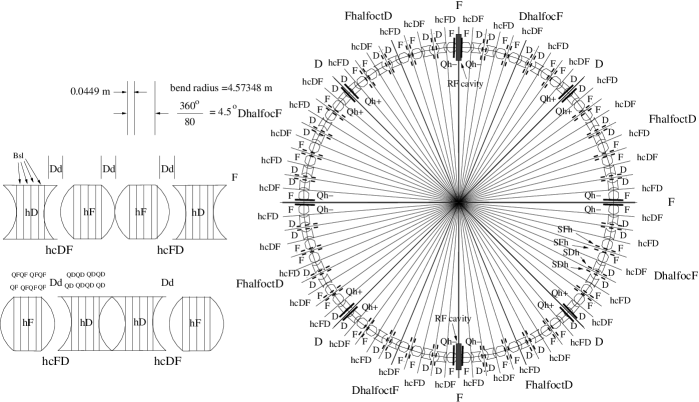
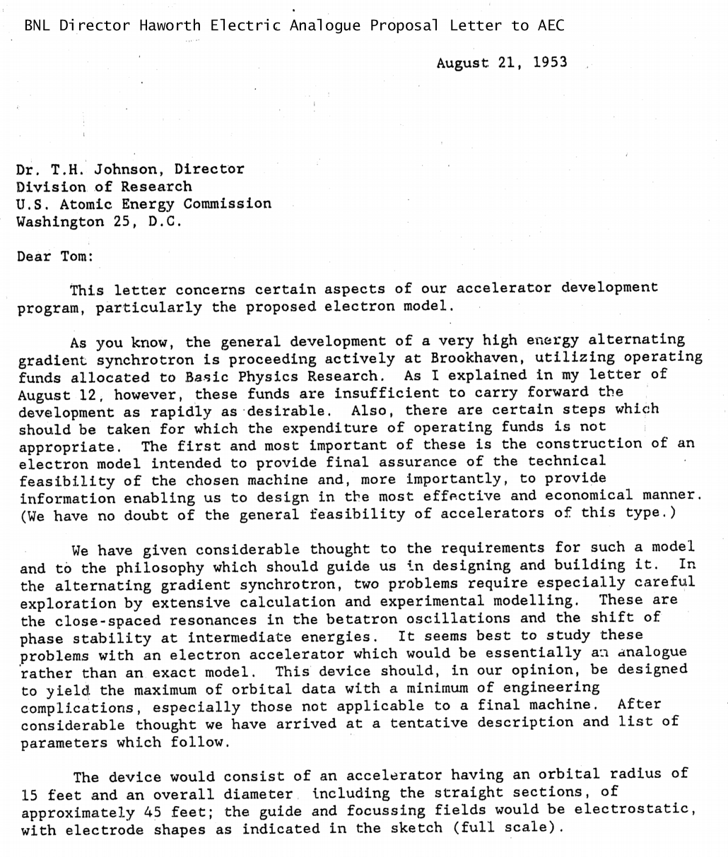
The “Conceptual Design Report” for the AGS Analogue electron ring was a four page letter, dated August 21, 1953, from BNL Director Haworth to the A.E.C. (predecessor of D.O.E.) Director of Research Johnson, applying for funding. The letter is reproduced in its entirety in Figure 7 in the appendix. As brief as it is, this letter along with hints from Plotkin and Courant, includes everything needed to reconstruct the ring, as shown in Figure 1. By 1955 the ring had been approved, built, and commissioned, and had achieved its intended purpose.
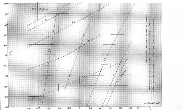
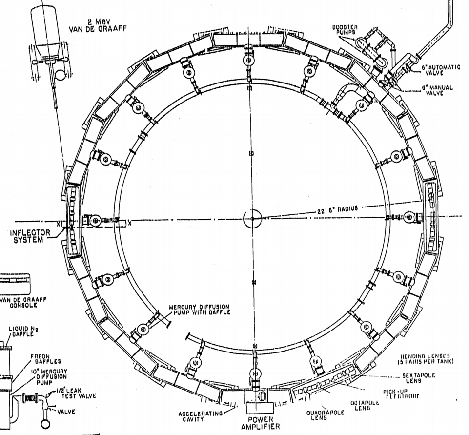
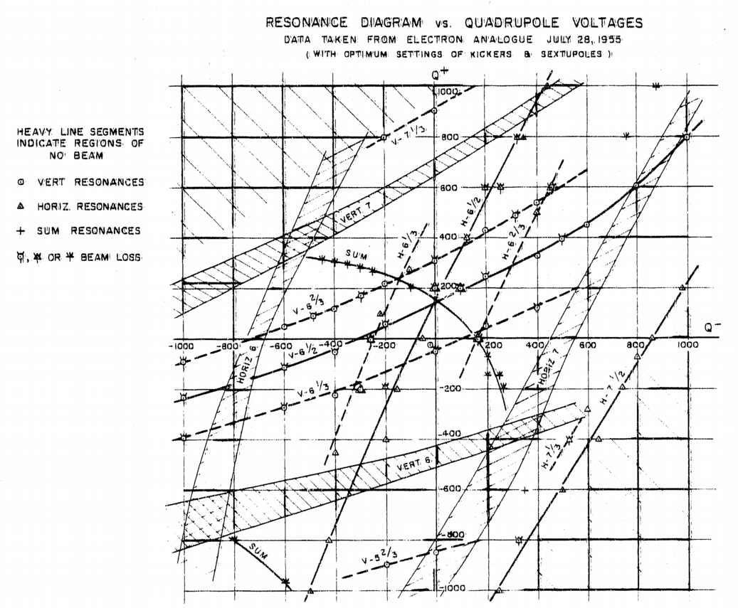
Following the Haworth letter in the appendix are two other especially informative figures from the paper by Plotkin. Figure 8 is especially useful for visualizing the physical layout of the AGS Analogue ring and its vacuum system. Figure 9 is a more polished version of Figure 3 which plots tune scans actually performed on the AGS-Analogue ring and reported by Ernest Courant in a July 28, 1955 BNL technical reportCourant .
In these plots, points of observed beam loss and observed beam disruption in the tune plane are correlated with expected resonances. Beam loss occurs on integer resonances, beam disruption occurs on half integer resonances. The Courant report on, and analysis of, data collected in machine studies less than two years after the submission of the ring funding proposal, would certainly deserve an A+ grade by modern machine studies grading standards.
The axes are voltages (proportional to focusing strengths) applied to the tune-adjusting quadrupole families. Short heavy lines indicate regions with no beam survival (presumably due to integer resonance). Dots indicate points reported by Courant as “showing the characteristic double envelope of the oscilloscope pattern, sometimes accompanied by beam loss”. (These were presumably due to “very narrow” 1/2 integer resonance). The nominal central tunes values are . Stop bands due to the eightfold lattice symmetry are also shown.
III Current day simulation of 1955 machine studies tune plane scan
Our AGS Analogue lattice reconstruction is shown in Figure 1. The Courant tune plane plot is shown in Figure 2. It is to be compared with a similar plot, simulated by TEAPOT and shown in Figure 3. As far as we know this code and this lattice representation are completely equivalent Courant’s model and analysis in 1955.
In the TEAPOT tune plane plot, boxes indicate points on integer resonance boundary curves of the stable diamond centered on nominal tune values . Points lying on 1/2 integer resonance lines are indicated by dots. Superperiodicity (eightfold periodicity) causes resonances with or indicated by broad blank bends bounded by narrowly-spaced lines. Courant refers to these as “stop bands”. Horizontal/vertical axes are “electrode voltages on the quadrupoles in odd/even-numbered tanks”. (For the meaning of “tank” see Figure 8.) The quadrupole strength coefficients for variable quadrupoles were determined empirically to match the central tunes. This means that absolute focusing strength scales are not checked. Otherwise there are no significantly adjustable empirical lattice parameters.
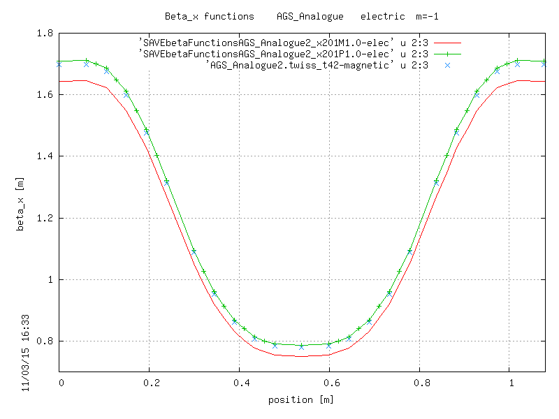
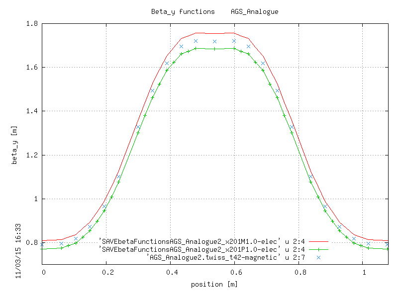
The AGS Analogue ring provides only a coarse test of ETEAPOT since, for strong focusing, the change from electic and magnetic bending is quite minor. This is illustrated in Figure 4 which shows that the =(6.5,6.5) tunes in the AGS Analogue ring are high enough that the tune plane structure is quite insensitive to whether the bends are treated as magnetic or electric.
Treating the difference perturbatively, the effects of changing from magnetic to electric bends are inversely proportional to ’s, which are both 6.5 in this case. For the eventual proton EDM ring the vertical tune has to be reduced from by at least a factor of ten which completely invalidates any such perturbative estimation and requires radical adjustment of quadrupole strengths. Reducing from 6.5 to 2.25 has been straightforward but, as the electric focusing became increasingly important, to decrease further will require substantial design effort.
Spin evolution in the AGS Analogue ring is shown in Figure 5 and described in the caption. From these results we are confident in out understanding of electric rings and of our ability to simulate their performance using ETEAPOT.

IV Long term tracking in a proton EDM storage ring trap
Plots so far have simulated the evolution of 10 MeV electrons in the AGS Analogue electron ring. These roughly indicate the performance to be expected in a modern day electron EDM storage ring measurement. Of more immediate interest is the expected behavior of 230 MeV protons in a significantly larger, but still all-electric proton EDM storage ring.
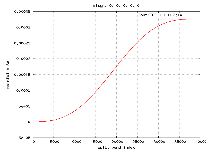
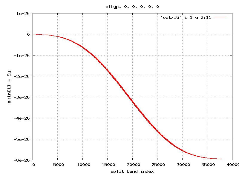
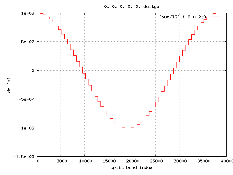
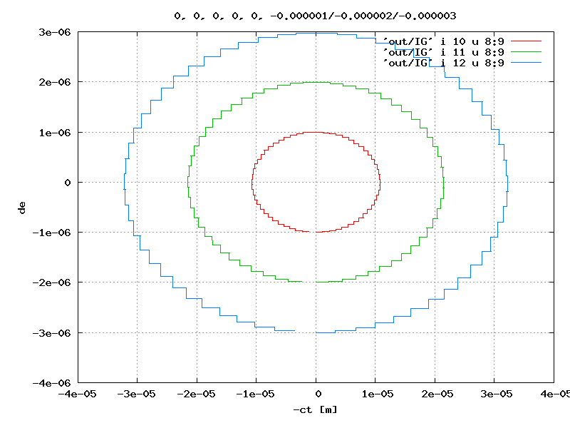
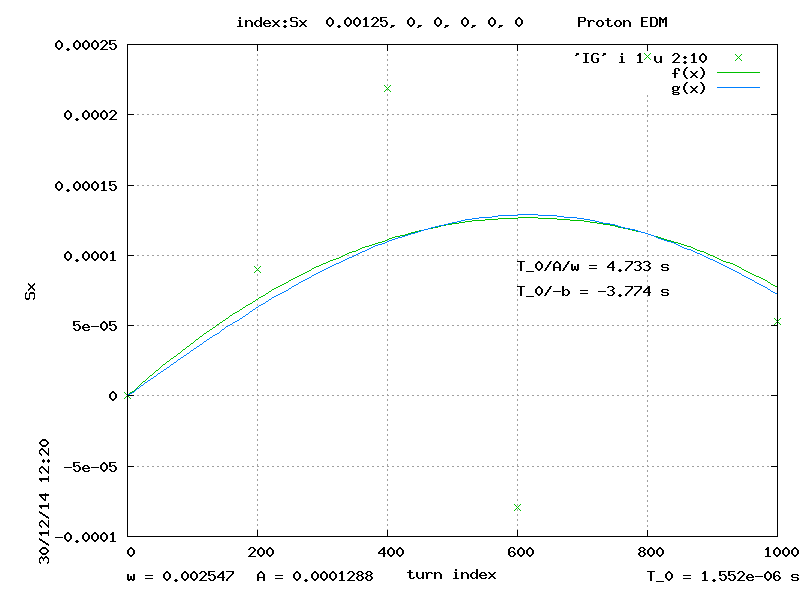
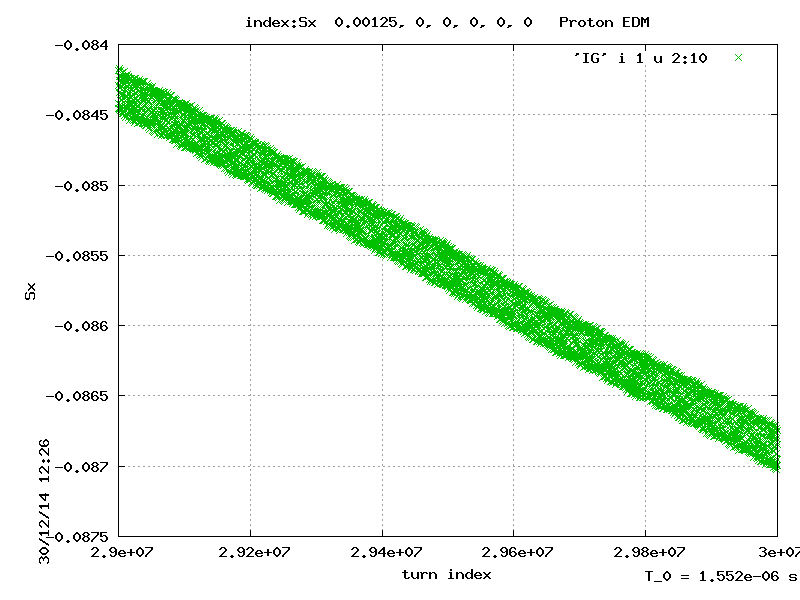
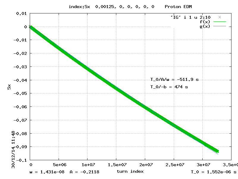
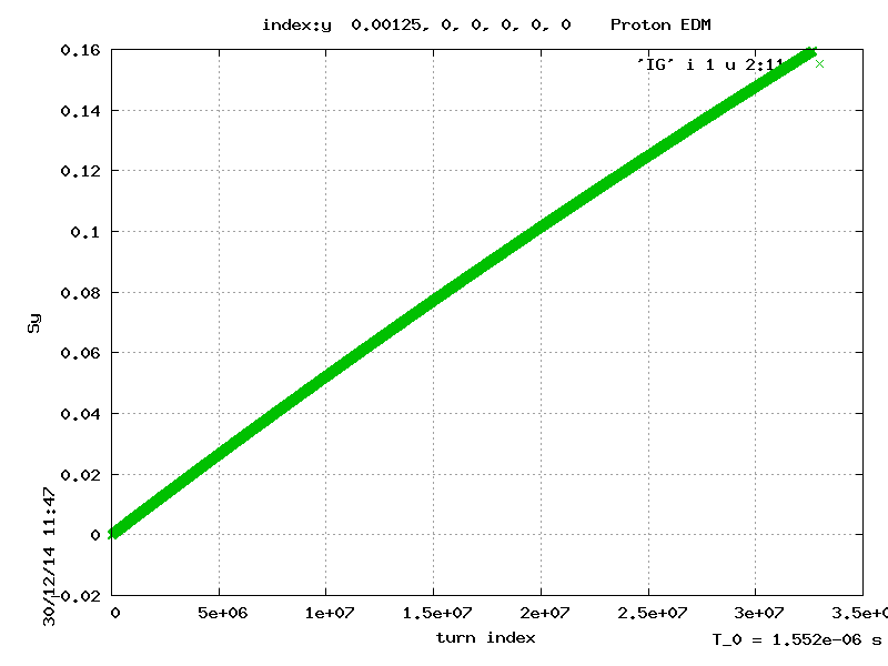
A single particle tracking example, taken from a recent proton EDM study, is illustrated in Figure 6. The particle orbit and spin components are tracked around a prototype proton EDM storage ring for 33 million turns using ETEAPOT. As stated earlier the tracking is exact and no artificial “symplectification” is applied. Any spurious damping or anti-damping of the spatial orbit over the full run is less than ten percent over the 33 million turns. The (unit-magnitude) spin vector S is initially purely tangential (forward) and the vector magnitude never changes from its initial value of 1.
It is characteristic of spin evolution for the transverse spin components to change over narrow ranges in synchronism with betatron oscillation and larger but still small, ranges in synchronism with synchrotron oscillation. The upper left graphs of Figure 6 show this, along with a sinusoidal fit with the parameters shown. These precessions are not expected to contribute significantly to spin decoherence. But any systematic growth over millions of turns will eventually lead to beam decoherence and limited spin coherence time.
An important computational task in planning to measure the proton EDM is to determine the spin coherence time of the circulating beam. This is the time after which inevitable spreads in beam parameters will have attenuated the beam polarization significantly due to decoherence in the spin propagation. As long as both and magnitudes remain small, S remains in the forward hemisphere, and decoherence is suppressed.
One sees from the graphs of Figure 6 that both and gradually deviate from zero. But, for the particular particle being tracked, these deviations are limited to small values. In particular, since remains always much less than 1 in magnitude, therefore remains not much less than 1. So the beam polarization remains always in the forward hemisphere. Depolarization is therefore unimportant for particles of amplitude comparable to, or smaller than, this particle’s. The tracking is therefore consistent with the SCT value exceeding the 33 million turns shown.
The lattice investigated in Figure 6 is a “Möbius lattice” in which the horizontal and vertical betatron oscillations interchange on every turn. This strongly suppresses spin depolarization because precession in horizontal and vertical oscillation phases tend to cancel on a turn-by-turn basis. By fine tuning this cancellation it is anticipated that extremely long SCT values can be obtained.
This will leave beam energy spread as the dominant source of beam depolarization. Fringe fields at bend elements are one such significant source of spin precession slewing. In this respect spin tracking is more sensitive than orbit tracking. Fringe fields are not very important in orbit calculations. Treating bends as “hard edged” mainly causes small tune shifts which are not very important, since both tunes are always set operationally using spectrum analysis. But, because of the spin precession sensitivity, in ETEAPOT, fringe fields are treated as linear ramps of length comparable with the gap between the electrodes, and not by hard edges. In any case synchrotron oscillation averaging also strongly suppresses this fringe field depolarization. This places further demands on longitudinal particle tracking, which is always delicates, because nonlinearity of synchrotron oscillations contributes to spin decoherence.
The particle revolution period is about one microsecond so the plots shown correspond to about thirty seconds of real clock time in the laboratory. In a laptop computer this computation takes a few hours per particle. The ratio of computation time to real laboratory time for a single particle is in the range from one to ten thousand. The present ETEAPOT single particle tracking approach is sufficient for early design tasks.
EDM storage ring beams will contain perhaps particles. Adequately precise simulation of the EDM experiment will require fewer than this, but at least thousands of particles to be tracked for significantly longer times than shown. This will require heavy parallelization of the tracking. With little particle-to-particle interaction, the code is easily parallelizable. For more advanced tasks, such as investigating polarimeter biases or emittance growth caused intrabeam scattering, an efficient and scalable map-based computational approach is under consideration.
![[Uncaptioned image]](/html/1503.08494/assets/PlotkinBNLpage16.png)
![[Uncaptioned image]](/html/1503.08494/assets/PlotkinBNLpage17.png)
![[Uncaptioned image]](/html/1503.08494/assets/PlotkinBNLpage18.png)
References
- (1) M. Plotkin, The Brookhave Electron Analogue, 1953-1957, BNL–45058, December, 1991
- (2) E. Courant, Resonance in the Electron Analogue, BNL internal report EDC-20, July 28, 1955
- (3) Recent private communication.
- (4) R. Talman and J. Talman, ETEAPOT: symplectic orbit/spin tracking code for all-electric storage rings
- (5) N. Malitsky and R. Talman, Unified Accelerator Libraries, AIP 391, Williamsburg, 1996. UAL website https://code.google.com/p/ual/
- (6) Proton EDM group, Storage Ring Electric Diplole Measurement, paper in preparation for submission to PRL
- (7) N. Malitsky, D. Reynolds, and R. Talman, Precise High-Performance Simulator for EDM Experiments¡ DOE Office of Science Application, 2015
- (8) I. Bazarov, Performance of a High Current, Low Emittance Electron Gun, Cornell Report, 2013
- (9) W. Morse, All Electric Magic Momentum Electron EDM Precursor Experiment¡ Brookhaven National Lab Internal Report, January 24, 2012
- (10) J. Talman and R. Talman, BNL internal reports, UAL/ETEAPOT Results for Proton EDM Benchmark Lattices, April, 2012, UAL/ETEAPOT Proton EDM Benchmark Comparisons II: Transfer Matrices and Twiss Functions, August, 2012, and UAL/ETEAPOT Proton EDM Benchmark Comparisons III: Dispersion, Longitudinal Dynamics and Synchrotron Oscillations, April, 2012