Spin dynamics and frequency dependence of magnetic damping study in soft ferromagnetic FeTaC film with a stripe domain structure
Abstract
Perpendicular magnetic anisotropy (PMA) and low magnetic damping are the key factors for the free layer magnetization switching by spin transfer torque technique in magnetic tunnel junction devices. The magnetization precessional dynamics in soft ferromagnetic FeTaC thin film with a stripe domain structure was explored in broad band frequency range by employing micro-strip ferromagnetic resonance technique. The polar angular variation of resonance field and linewidth at different frequencies have been analyzed numerically using Landau-Lifshitz-Gilbert equation by taking into account the total free energy density of the film. The numerically estimated parameters Landé -factor, PMA constant, and effective magnetization are found to be 2.1, 2 erg/cm3 and 7145 Oe, respectively. The frequency dependence of Gilbert damping parameter () is evaluated by considering both intrinsic and extrinsic effects into the total linewidth analysis. The value of is found to be 0.006 at 10 GHz and it increases with decreasing precessional frequency.
Spin transfer torque (STT) has grater credibility compared to other techniques towards ultrafast spin dynamics in ferromagnet by electric current induced magnetization reversal of spin valves and magnetic tunnel junctions (MTJ).Sankey et al. (2008) The current researchers are more keen to focus on STT technology for its high density magnetic random access memories (MRAM),Devolder et al. (2008); Huai et al. (2004) STT-driven domain wall devicesFukami (2009) and perpendicular magnetic recording mediaKhizroev and Litvinov (2004) applications. In order to make this technology more efficient, lowering the critical current density is essential which requires the material specifications with low saturation magnetization (), high spin polarization, large uniaxial perpendicular magnetic anisotropy (PMA) constant and low magnetic damping.Mizukami et al. (2013); Song et al. (2013); Guo et al. (2014) The magnetic damping parameter () can be described well by the phenomenological Landau-Lifshitz-Gilbert equation and is known as the Gilbert damping.Landau and Lifshitz (1935); Gilbert (1955) Several attempts have been made for understanding the origin of Gilbert damping in spin dynamics relaxation in single layer as well as multilayered magnetic alloys, which arises from both intrinsic and extrinsic parts of the material. The intrinsic contribution to the Gilbert damping parameter has been studied by tuning the strength of the spin-orbit coupling.He et al. (2013); Guo et al. (2014); Woltersdorf et al. (2009) Recently, Ikeda et al.Ikeda et al. (2010) have reported that CoFeB-MgO based MTJ with PMA would be reliable for high-density non-volatile memory application due to its high thermal stability and efficiency towards STT technology. The investigation on magnetic dynamics, PMA and the apparent magnetic damping have been studied extensively in CoFeB based soft ferromagnetic thin film by ferromagnetic resonance (FMR) and time-resolved magneto-optical Kerr effect.Hirayama et al. (2015); Lu et al. (2014) Malinowski et al. Malinowski et al. (2009) have reported a large increase in Gilbert damping with applied magnetic field in perpendicularly magnetized CoFeB thin film.
In this letter, we focus on amorphous FeTaC layer due to its interesting soft ferromagnetic (FM) properties.Tanahashi et al. (2003); Singh et al. (2012) The amorphous soft FM layer reduces the number of pinning centers which may lead to the STT-driven domain wall motion along with high tunneling magnetoresistance ratio (TMR). The transcritical loop along with the stripe domain structure, which are the manifestation of PMA component were reported on FeTaC thin film with thickness of 200 nm.Singh et al. (2012, 2013) To shed some more light onto its dynamic magnetic properties, we have further studied this film by using ferromagnetic resonance technique. Though the magnetic anisotropy and Gilbert damping have been studied by FMR technique in several magnetic thin films like Heusler alloys, permalloy, soft magnetic materials and multilayered (FM/antiferromagnetic or non-magnetic/FM) magnetic films for magnetic recording, MTJ and TMR reader applications, most of the reports are limited to single frequency due to the measurements in X-band electron-spin-resonance spectrometer where the cavity resonates at particular frequency.Zakeri et al. (2007); Gong et al. (2009); Pandey et al. (2012); Mizukami et al. (2013); Guo et al. (2014); Behera et al. (2015); Lu et al. (2014) In this report, spin dynamics and magnetic relaxation are studied at different magnetization precessional frequencies.
Soft ferromagnetic Fe80Ta8C12 single layer film with thickness 200 nm was deposited by dc magnetron sputtering technique and the details of growing environment were reported earlier.Singh et al. (2012) The static and dynamic magnetic properties were explored by using a vector network analyzer (VNA) based homemade micro-strip ferromagnetic resonance (MS-FMR) spectrometer. The micro-strip line which was coupled to VNA and Schottky diode detector (Agilent 8473D) through high frequency coaxial cables was mounted in between the pole pieces of the electromagnet. The magnetic thin film with film side downward was mounted on the strip line. The frequency of the microwave signal was fixed by using an Agilent Technologies made VNA (Model PNA-X, N-5242A) with a constant microwave power of 5 dBm. The first derivative of the absorption spectrum with respect to magnetic field () was collected by field modulation and lock-in detection technique. The FM thin film was treated in-plane and out-of-plane orientations. The magnetic field sweeping FMR spectra were recorded by varying two parameters: precessional frequency and the angle between and normal of the film. The frequency () and polar angle () dependence of resonance field () and linewidth () were extracted from each FMR spectrum and the numerical calculations were carried out by mathematica program for different relaxation processes.
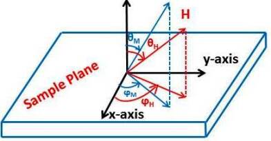
The precession of magnetization () in the sample plane under the influence of microwave and external magnetic field is illustrated in Fig. 1 in a polar coordinate system. () is the in-plane angle between () and axis and () is the polar angle between axis and (). The uniform precession of magnetization can be described by the Landau-Lifshitz-Gilbert (LLG) equation of motion,Landau and Lifshitz (1935); Gilbert (1955)
| (1) |
The first term corresponds to the precessional torque in the effective magnetic field and the second term is the Gilbert damping torque. is denoted as gyromagnetic ratio and written in terms of Landé factor, Bohr magneton , and Planck constant . is related to the intrinsic relaxation rate of the material. is the dimensionless Gilbert damping parameter. The free energy density of a single magnetic thin film can be written as,
| (2) |
where the first term is analogous to the Zeeman energy, the second term is dipolar demagnetization energy, the third term signifies the anisotropy energy, is the saturation magnetization, is the PMA constant with corresponding anisotropic field . The resonance frequency of the uniform precession mode is deduced from the energy density by using the following expression,Acher et al. (2003)
| (3) |
where the derivatives are evaluated at equilibrium positions of and .
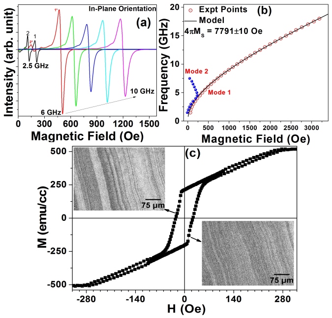
For the in-plane orientation, the typical FMR spectra at different frequencies are shown in Fig. 2(a). The measurements were carried out by varying the frequency from 1 to 18 GHz with an interval of 0.5 GHz. In the lower frequency range 1-6 GHz, the FMR spectra show two resonance peaks. The low-field resonance peaks named as secondary mode and are marked by 2 and 2∗ for 2.5 and 6 GHz, respectively in Fig. 2(a). This mode arises from the linear unsaturated zone of the transcritical () loop Singh et al. (2013) and is usually observed in stripe-domain structure.Acher et al. (1997); Vukadinovic et al. (2001) The transcritical loop along with the domain structure are reproduced from earlier reportSingh et al. (2013) and is shown in Fig. 2(c). The dense stripe-domain structure observed in this film confirms the presence of perpendicular magnetic anisotropy. The primary modes usually called uniform mode are marked as 1 and 1∗ for 2.5 and 6 GHz, respectively. The value of for secondary resonance peak increases with the increase in up to 4.5 GHz and then follows the reverse trend as depicted in Fig. 2(b). This could be explained on the basis that the value of of the uniform mode above 4.5 GHz overcomes the parallel saturation field, i.e., 280 Oe as observed in () curve. Above 6 GHz, exceeds the parallel saturation field in large extent and this could be the reason for the strong attenuation of secondary phase. In planar configuration (==), the solution for the in-plane resonance frequency can be calculated by incorporating the total energy in Eq. 3 and is given by,
| (4) |
The value of can be calculated by using the solution of at equilibrium condition, i.e., 0. However, for the present thin film, we could not find any planar anisotropy from the dependence of and hence conclude, = . The dependence of is numerically calculated by using Eq. 4 and is shown as a solid line in Fig. 2(b). The numerically calculated values yielded a good fit and the parameters are found to be reliable with = 779110 Oe and = 2.95 MHz/Oe with a -factor of 2.1. The deduced value of saturation magnetization is very close to earlier reported value from () loop measurement.Singh et al. (2012)
In out-of-plane configuration, the solution for the resonance frequency is deduced from Eq. 3 by employing the conditions, == and is represented in Eq. 5.
| (5) |
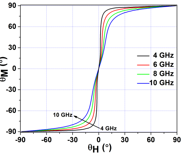
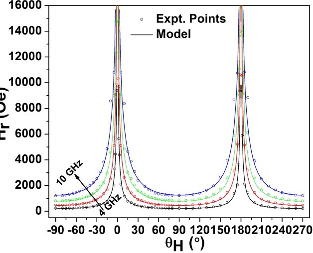
The equilibrium angle is numerically calculated for each value of by minimizing the energy, i.e., and is depicted in Fig. 3 for different frequencies. Fig. 3 demonstrates that magnetization suddenly attempts to align in planar direction as the magnetic field goes away from the =0∘ and 180∘. Fig. 4 shows one complete round of dependence of at different frequencies. Uniaxial PMA is found to be observed along with singularity at and , which signifies that infinite magnetic field is required to turn the vector parallel to in perpendicular configuration. The dependence of on is modeled at different frequencies starting from 4 to 10 GHz with 2 GHz intervals by using Eq. 5 and the interpolated values of from Fig. 3. The modeled values of are plotted as a solid line in Fig. 4 and a very good agreement with experimental data is observed. The parameters deduced from this calculation are found to be erg/cm3 and 47145 Oe.
Finally, the damping of magnetization precession has been analyzed from linewidth of FMR spectra. The dependence of as shown in Fig. 5 was extracted from the polar angle variation of FMR spectrum at different frequencies in the range of 4-10 GHz with an interval of 2 GHz. In order to get better clarity of Fig. 5, the data for the 4 GHz frequency are not shown. The total linewidth broadening due to the intrinsic and extrinsic parts of the material has been expressed in the following equation,Mizukami et al. (2002); Guo et al. (2014)
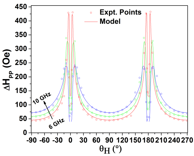
| (6) |
where , is the effective magnetization. arises from the intrinsic Gilbert type damping and has large contribution towards linewidth broadening. The parameter signifies how fast the precessional energy is dissipated into the lattice. The terms and represent the linewidth broadening due to the spatial dispersion of the magnitude and direction of , respectively. The dependence of was modeled by using Eq. 6 and the interpolated values of from Fig. 3 at different frequencies. The numerically calculated values of are shown as solid lines in Fig. 5. The individual contributions towards the total linewidth () is also shown in Fig. 6.
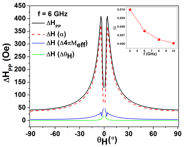
The curves are shown for a single frequency for better clarity. The linewidth broadening is observed mainly due to the intrinsic Gilbert damping. The extrinsic contribution is found to be negligible when is away from and but it is large near the perpendicular configuration. The Gilbert damping parameter at different frequencies for the FeTaC thin film is plotted in the inset of Fig. 6. It shows that the decrease monotonically with the increase in frequency. The low value of damping parameter observed in the present thin film can be more relevant towards the STT technology or MTJ applications. Such an increase of by decreasing precessional frequency has been attributed to the inhomogeneous linewidth broadening due to the dispersion of anisotropic field.Celinski and Heinrich (1991); Silva et al. (1999) The dispersion in magnitude and direction of effective magnetization are found to be =0.1 KOe, degree. The value of Gilbert damping constant for the present FeTaC thin film is found to be comparable to those reported in Fe-based magnetic thin films, such as FePd ternary alloyHe et al. (2013), permalloyCounil et al. (2004), NiFe/CoFeB/CoFe multilayered stuructureLu et al. (2014) and (FeCo)1-xGdxGuo et al. (2014). However, the Mn- and Co- based thin filmsMizukami et al. (2013); Song et al. (2013) have larger damping parameter as compared to the present film which could be understood on the basis of spin-orbit coupling.
In conclusion, PMA and Gilbert damping which are very important and crucial parameters for STT, STT-MRAM and TMR applications, have been analyzed in FeTaC soft ferromagnetic thin film with a striped domain structure by using MS-FMR technique in broad band frequency range. The precise estimation of Landé -factor, PMA constant and were carried out by using total energy density function for magnetic thin film. Spin dynamics relaxation which is quantified by Gilbert damping parameter has been analyzed at different frequencies and is found to be 0.006 which falls in the most reliable order from application point of view. The values of are found to be comparable to those reported Fe-based single layer and multilayered magnetic thin films.
Acknowledgement
The authors would like to thank Dr. Najmul Haque for helping to write energy minimization calculation in mathematica and Mr. Nazir Khan for his help during writing data acquisition software.
References
- Sankey et al. (2008) J. Sankey, Y.-T. Cui, J. Sun, J. Slonczewski, R. Buhrman, and D. Ralph, “Measurement of the spin-transfer-torque vector in magnetic tunnel junctions,” Nature Physics, 4, 67–71 (2008).
- Devolder et al. (2008) T. Devolder, J. Hayakawa, K. Ito, H. Takahashi, S. Ikeda, P. Crozat, N. Zerounian, J.-V. Kim, C. Chappert, and H. Ohno, “Single-shot time-resolved measurements of nanosecond-scale spin-transfer induced switching: Stochastic versus deterministic aspects,” Phys. Rev. Lett., 100, 057206 (2008).
- Huai et al. (2004) Y. Huai, F. Albert, P. Nguyen, M. Pakala, and T. Valet, “Observation of spin-transfer switching in deep submicron-sized and low-resistance magnetic tunnel junctions,” Applied Physics Letters, 84, 3118–3120 (2004).
- Fukami (2009) S. T. e. a. Fukami, S., “Low-current perpendicular domain wall motion cell for scalable high-speed mram,” Dig. Tech. Pap.- Symp. VLSI Technol., 24, 230 (2009).
- Khizroev and Litvinov (2004) S. Khizroev and D. Litvinov, “Perpendicular magnetic recording: Writing process,” Journal of Applied Physics, 95, 4521–4537 (2004).
- Mizukami et al. (2013) S. Mizukami, A. Sakuma, T. Kubota, Y. Kondo, A. Sugihara, and T. Miyazaki, “Fast magnetization precession for perpendicularly magnetized mnalge epitaxial films with atomic layered structures,” Applied Physics Letters, 103, 142405 (2013).
- Song et al. (2013) H.-S. Song, K.-D. Lee, J.-W. Sohn, S.-H. Yang, S. S. P. Parkin, C.-Y. You, and S.-C. Shin, “Relationship between gilbert damping and magneto-crystalline anisotropy in a ti-buffered co/ni multilayer system,” Applied Physics Letters, 103, 022406 (2013).
- Guo et al. (2014) X. Guo, L. Xi, Y. Li, X. Han, D. Li, Z. Wang, and Y. Zuo, “Reduction of magnetic damping constant of feco films by rare-earth gd doping,” Applied Physics Letters, 105, 072411 (2014).
- Landau and Lifshitz (1935) L. Landau and E. Lifshitz, Phys. Z. Sowjetunion, 8, 153 (1935).
- Gilbert (1955) T. L. Gilbert, Phys. Rev., 100, 1243 (1955).
- He et al. (2013) P. He, X. Ma, J. W. Zhang, H. B. Zhao, G. Lüpke, Z. Shi, and S. M. Zhou, “Quad ratic scaling of intrinsic gilbert damping with spin-orbital coupling in l1 0 fepdpt films: Experiments and ab initio calculat ions,” Phys. Rev. Lett., 110, 077203 (2013).
- Woltersdorf et al. (2009) G. Woltersdorf, M. Kiessling, G. Meyer, J.-U. Thiele, and C. H. Back, “Damping by slow relaxing rare earth impurities in ni80fe20,” Phys. Rev. Lett., 102, 257602 (2009).
- Ikeda et al. (2010) S. Ikeda, K. Miura, H. Yamamoto, K. Mizunuma, H. D. Gan, M. Endo, S. Kanai, J. Hayakawa, F. Matsukura, and H. Ohno, “A perpendicular-anisotropy cofeb–mgo magnetic tunnel junction,” Nat. Mater., 9, 721–724 (2010).
- Hirayama et al. (2015) E. Hirayama, S. Kanai, H. Sato, F. Matsukura, and H. Ohno, “Ferromagnetic resonance in nanoscale cofeb/mgo magnetic tunnel junctions,” Journal of Applied Physics, 117, 17B708 (2015).
- Lu et al. (2014) L. Lu, Z. Wang, G. Mead, C. Kaiser, Q. Leng, and M. Wu, “Damping in free layers of tunnel magneto-resistance readers,” Applied Physics Letters, 105, 012405 (2014).
- Malinowski et al. (2009) G. Malinowski, K. C. Kuiper, R. Lavrijsen, H. J. M. Swagten, and B. Koopmans, “Magnetization dynamics and gilbert damping in ultrathin co48fe32b20 films with out-of-plane anisotropy,” Applied Physics Letters, 94, 102501 (2009).
- Tanahashi et al. (2003) K. Tanahashi, A. Kikukawa, Y. Takahashi, and Y. Hosoe, “Laminated nanocrystalline soft underlayers for perpendicular recording,” Journal of Applied Physics, 93, 6766–6768 (2003).
- Singh et al. (2012) A. K. Singh, B. Kisan, D. Mishra, and A. Perumal, “Thickness dependent magnetic properties of amorphous fetac films,” Journal of Applied Physics, 111, 093915 (2012).
- Singh et al. (2013) A. K. Singh, S. Mallik, S. Bedanta, and A. Perumal, “Spacer layer and temperature driven magnetic properties in multilayer structured fetac thin films,” Journal of Physics D: Applied Physics, 46, 445005 (2013).
- Zakeri et al. (2007) K. Zakeri, J. Lindner, I. Barsukov, R. Meckenstock, M. Farle, U. von Hörsten, H. Wende, W. Keune, J. Rocker, S. S. Kalarickal, K. Lenz, W. Kuch, K. Baberschke, and Z. Frait, “Spin dynamics in ferromagnets: Gilbert damping and two-magnon scattering,” Phys. Rev. B, 76, 104416 (2007).
- Gong et al. (2009) Y. Gong, Z. Cevher, M. Ebrahim, J. Lou, C. Pettiford, N. X. Sun, and Y. H. Ren, “Determination of magnetic anisotropies, interlayer coupling, and magnetization relaxation in fecob/cr/fecob,” Journal of Applied Physics, 106, 063916 (2009).
- Pandey et al. (2012) H. Pandey, P. C. Joshi, R. P. Pant, R. Prasad, S. Auluck, and R. C. Budhani, “Evolution of ferromagnetic and spin-wave resonances with crystalline order in thin films of full-heusler alloy co2mnsi,” Journal of Applied Physics, 111, 023912 (2012).
- Behera et al. (2015) N. Behera, M. S. Singh, S. Chaudhary, D. K. Pandya, and P. K. Muduli, “Effect of ru thickness on spin pumping in ru/py bilayer,” Journal of Applied Physics, 117, 17A714 (2015).
- Acher et al. (2003) O. Acher, S. Queste, M. Ledieu, K.-U. Barholz, and R. Mattheis, “Hysteretic behavior of the dynamic permeability on a ni-fe thin film,” Phys. Rev. B, 68, 184414 (2003).
- Acher et al. (1997) O. Acher, C. Boscher, B. Brulé, G. Perrin, N. Vukadinovic, G. Suran, and H. Joisten, “Microwave permeability of ferromagnetic thin films with stripe domain structure,” Journal of Applied Physics, 81, 4057–4059 (1997).
- Vukadinovic et al. (2001) N. Vukadinovic, M. Labrune, J. B. Youssef, A. Marty, J. C. Toussaint, and H. Le Gall, “Ferromagnetic resonance spectra in a weak stripe domain structure,” Phys. Rev. B, 65, 054403 (2001).
- Mizukami et al. (2002) S. Mizukami, Y. Ando, and T. Miyazaki, “Effect of spin diffusion on gilbert damping for a very thin permalloy layer in cu/permalloy/cu/pt films,” Physical Review B, 66, 104413 (2002).
- Celinski and Heinrich (1991) Z. Celinski and B. Heinrich, “Ferromagnetic resonance linewidth of fe ultrathin films grown on a bcc cu substrate,” Journal of Applied Physics, 70, 5935–5937 (1991).
- Silva et al. (1999) T. J. Silva, C. S. Lee, T. M. Crawford, and C. T. Rogers, “Inductive measurement of ultrafast magnetization dynamics in thin-film permalloy,” Journal of Applied Physics, 85, 7849–7862 (1999).
- Counil et al. (2004) G. Counil, J.-V. Kim, T. Devolder, C. Chappert, K. Shigeto, and Y. Otani, “Spin wave contributions to the high-frequency magnetic response of thin films obtained with inductive methods,” Journal of Applied Physics, 95, 5646–5652 (2004).