Superlubric to stick-slip sliding of incommensurate graphene flakes on graphite
Abstract
We calculate the friction of fully mobile graphene flakes sliding on graphite. For incommensurately stacked flakes, we find a sudden and reversible increase in friction with load, in agreement with experimental observations. The transition from smooth sliding to stick-slip and the corresponding increase in friction is neither due to rotations to commensurate contact nor to dislocations but to a pinning caused by vertical distortions of edge atoms also when they are saturated by Hydrogen. This behavior should apply to all layered materials with strong in-plane bonding.
pacs:
68.35.Af,62.20.Qp,68.37.Ps,81.05.ufI Introduction
Since the discovery of graphene Novoselov et al. (2004), there is a growing interest in materials similar to graphite, with strongly bonded 2D sheets and weak interplanar coupling Lebègue et al. (2013). This type of bonding makes these lamellar materials, and graphite in particular, also interesting as solid lubricants. Since the first Friction Force Microscope (FFM) measurements by Mate et al. Mate et al. (1987) graphite has been a prototype system for nanotribology, the new research field that aims at understanding the fundamental origin of friction at the atomic scale. To model the friction in graphitic materials, it is important to go beyond the Tomlinson model of a point-like tip Tomlinson (1929); Prandtl (1928); Hölscher et al. (1998) and consider the tip as an extended contact. In fact, to account for the order of magnitude of the experimentally measured friction on graphite, it was proposed that a graphene flake was dragged along with the tip so that the friction between a graphene flake and graphite was measured instead of that between tip and graphite Morita et al. (1996); Sasaki et al. (1998); Dienwiebel et al. (2004). For such an extended contact, the friction strongly depends on the orientation of the flake with respect to the substrate. When the flake has the same orientation as the substrate, the contact is commensurate with high energy barriers to sliding and thus high friction. This is the most energetically favorable configuration, except near the edges of the substrateCruz-Silva et al. (2004). For angles in between commensurate situations, the flake is approximately incommensurate and the potential barriers to sliding are averaged out. In this situation, an almost frictionless sliding was observed Hirano and Shinjo (1993); Dienwiebel et al. (2004); Feng et al. (2013), a phenomenon often referred to as superlubricity Shinjo and Hirano (1993); Erdemir and Martin (2007); Gnecco et al. (2008); van den Ende et al. (2012).
Recently, extremely high speed superlubricity has been observed for micron sized graphene flakes Yang et al. (2013). However, for finite flakes, superlubricity is not necessarily a stable state. Further experiments and numerical simulations showed that graphene flakes of the order of 100 carbon atoms very often rotate to the commensurate orientation with a large and irreversible increase of friction Filippov et al. (2008). This finding was further supported by theoretical work, although stable orbits are predicted to exist de Wijn et al. (2010).
A sudden increase of friction was also measured for incommensurate graphene flakes with increasing load Dienwiebel (2003), as shown in Fig. 1. Since the observed increase in friction was found to be reversible, it could not be explained by rotations to the commensurate state. Reversibility also rules out plastic deformations of the substrate. Models with rigid flakes cannot explain this increase since, for incommensurate contacts, the corrugation remains too flat for the occurrence of stick-slip instabilities Tomlinson (1929); Prandtl (1928); Gnecco et al. (2008). Bonelli et al Bonelli et al. (2009) did simulations on non-rigid graphene flakes, but they only discussed the influence of load strongly limiting the deformations of the flake by means of very stiff springs (=2.5 eV/Å2).
Under load, a breakdown of superlubricity can also occur if strong in-plane distortions lead to local commensurability. This effect was reported by Kim and Falk Kim and Falk (2009) for a model system of atoms with Lennard-Jones and harmonic interactions. They showed that the tip would adjust to the substrate with higher load or weaker harmonic interaction between tip atoms. This adjustment led to local commensurability and consequently to the breakdown of superlubricity. Here we show that the reversible increase of friction with load shown in Fig. 1 is instead due to pinning of the edge atoms involving mostly vertical motion and very little in-plane strain in the flake. This mechanism seems to be specific of lamellar materials where the creation of defects or dislocations is energetically very unfavorable, contrary to the case of metal and rare gas islands on surfaces where the occurrence of dislocations dominates the diffusion Hamilton et al. (1995).

II Model
We construct a model of a FFM experiment where a graphene flake made of atoms is attached through springs to a tip that is moved on a graphite substrate. We allow the atoms of the flake to move in all directions whereas we keep the substrate atoms at their equilibrium positions in a flat hexagonal lattice at . The tip is modeled by attaching, in the and directions, each atom of the flake to springs at the positions of a rigid support flake of the same shape as shown in Fig. 2a. Alternatively, one could attach a spring to the center of mass, but this would not limit the rotations of the flake towards a commensurate contact, which is not the physical situation we want to consider. We model the load as a constant force on each atom and report either the load per atom or the total load on the flake given as the sum of the load on all atoms. The interaction between the atoms in the flake is given by the REBO potential Stuart et al. (2000); Brenner et al. (2002) as implemented in the molecular dynamics (MD) code LAMMPS Plimpton et al. (1995). The equilibrium interatomic distance is 1.3978 Å which is close to the experimental value 1.42 Å, giving a periodicity in the direction Å. We describe the interlayer interactions in graphitic systems by means of the the Kolmogorov-Crespi (KC) potential Kolmogorov and Crespi (2005). This combination has been shown to accurately reproduce the potential energy surface due to the substrate Reguzzoni et al. (2012) which is underestimated by the Lennard-Jones potential in AIREBO Stuart et al. (2000). With this potential the interplanar distance in graphite is 3.34 Å, with an energy gain of 48 meV/atom and a difference of 15 meV/atom between AA and AB stacking.
The forces acting on the flake atoms are given by
| (1) |
where the spring force on atom is
| (2) |
where and are the in plane coordinates of the flake atom and its support point respectively, as indicated in Fig. 2a. The spring constant is taken to be 16 meV/Å2.
The component in the pulling direction of the total spring force,
| (3) |
is often called the lateral force and its average over time gives the friction force . In fact, it can be shown that the average of the lateral force over a period of length is
| (4) |
where is equal to the energy dissipated over a period of length Fasolino . In our simulations, we use the first period as a transient and evaluate by averaging over the subsequent three periods. Notice that, in absence of interactions with the substrate, although each spring force can be different from zero due to relaxation of the flake induced by the edge termination with respect to the fixed support points.
The load on atom is a constant force
| (5) |
where is the total load on the flake.
Since the contact area of the flake has been estimated to be of the order of a hundred atoms Verhoeven et al. (2004); Dienwiebel et al. (2004), we choose flakes with hexagonal symmetry consisting of , and atoms. We will mostly consider the case where the flake is rotated by 30 degrees with respect to the substrate to ensure incommensurability as shown in Fig. 2b. This angle corresponds to an incommensurate contact for infinite lattices. By shifting the starting position of the incommensurate flake orthogonally to the pulling direction we examine the different scanlines indicated in Fig. 2b.
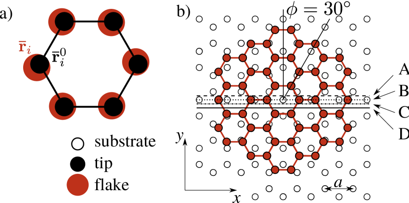
The speed of a FFM is so low ( nm/s) that, to a good approximation, the movement can be considered static. We therefore follow the approach by Bonelli et al. Bonelli et al. (2009) and use a quasistatic approach in which the support is moved in steps along a given scanline and the flake is relaxed after each step by minimizing the force (Eq. 1) on each atom. We use the FIRE scheme Bitzek et al. (2006), a damped dynamics algorithm, as implemented in LAMMPS Plimpton et al. (1995). We use 200 minimizations per period, which gives a step size for the movement of the support of 0.012 Å. The minimization stops when the norm of the global force vector becomes less than 3.12 eV/Å. We repeat this procedure for 4 periods to confirm periodicity and evaluate as described above. We found that the FIRE scheme is superior to conjugate gradients methods in satisfying the expected periodicity of the motion.
In comparison with tight binding Bonelli et al. (2009), our model is more suitable to study the effect of load due to the longer cut-off. The 3.34 Å interlayer distance in graphite is much longer than the cut-off range used in the tight binding model (2.6 Å).
The quasistatic approach does not include dynamic and temperature effects. In some cases, we therefore compare results obtained by this method to MD simulations at constant temperature using a Langevin thermostat. We choose a damping parameter of 0.6 ps, a timestep of 1 fs, temperatures of 10 K and 300 K and move the support with a speed of m/s.
III Results
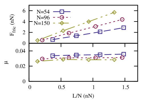
In general, incommensurate contacts lead to much lower friction than commensurate ones. In Fig. 3 we show the friction as a function of load for flakes with orientation , commensurate to the substrate. The friction linearly increases with load, resulting in a nearly constant friction coefficient , which agrees well with the experimental value found for microscale graphene Marchetto et al. (2012). It is worth noting that slightly decreases with size as a result of the fact that atoms at the edges can reach deeper minima and contribute more to the friction.
In experiments, the point of zero friction would occur at negative values of load due to the attractive van der Waals forces between tip and substrate. As in our simulations only the contact area of the tip and substrate is modeled, the van der Waals forces are very small and already at the friction is nearly zero.
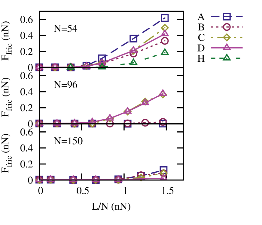
The effect of the edges becomes more dramatic for incommensurate contacts. In this case, the friction is drastically different from the one just discussed for commensurate cases. In Fig. 4 we show the variation of the friction force with increasing load for the 54, 96 and 150 atom flakes and the A,B,C,D scanlines. Smaller, 24 atom, flakes are not included because they rotate to the commensurate orientation already at low load, due to the smaller moment of inertia. We see that at low load, the friction is indeed almost vanishing as expected for truly incommensurate cases Peyrard and Aubry (1983); van den Ende et al. (2012).
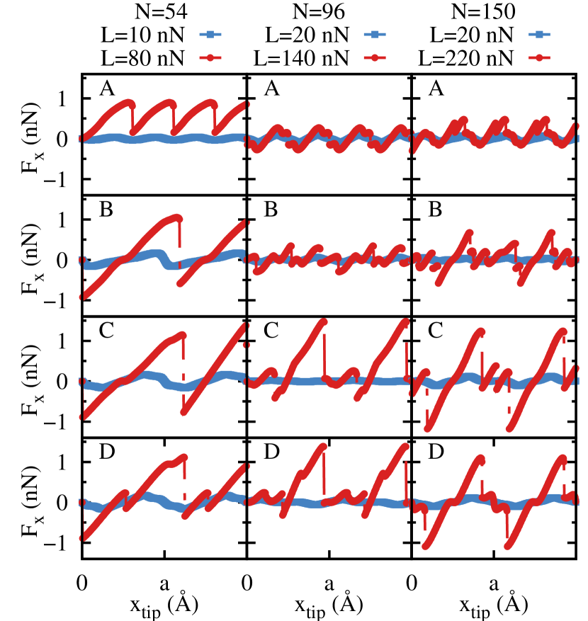
At higher loads, not only is the friction at least one order of magnitude lower than for commensurate flakes but the dependence on load is also much more complex. In most cases, the friction suddenly increases from a certain threshold load onwards in a way similar to the experimental situation shown in Fig. 1a. The increase in friction is stronger, and starts at a slightly lower load, for smaller flakes. For the 96 atom flakes, the increase starts at nN or nN, which is close to the experimental value Dienwiebel (2003). The large increase in friction with load corresponds to the transition from smooth motion to stick-slip behavior shown in Fig. 5. For an incommensurate contact, stick-slip motion is very unusual and would only be expected for very small flakes which, strictly speaking, are not incommensurate with the substrate Reguzzoni and Righi (2012).
Fig. 4 also shows that the behavior with load is not the same for all scanlines and flake sizes. First, we examine in detail the simplest case to explain the behavior with load and the effect of deformations and thereafter we will discuss the general features for all scanlines and flake sizes.
The simplest case is presented by the 54 atom flake along scanline D because the flake remains at 30 degrees and its center of mass does not deviate from the scanline, as shown in Fig. 6. We will focus on the role of deformations of the flake which are usually neglected.

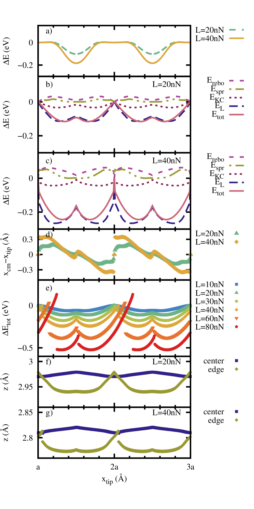
A priori, it is not obvious whether to expect higher or lower friction by considering a non-rigid flake instead of a rigid one. While barriers are easier to circumvent by deforming in addition to shifting and rotating, the same freedom could be used to find deeper minima. Therefore we examine the energy profile before looking at the friction. In Fig. 7a we show the potential energy due to the substrate calculated for a rigid flake kept at a fixed height, corresponding to the average height at the given load. We see that there is a smooth minimum at , that becomes deeper with load. To show the importance of the deformation of the flake, we compare this result to the energy profile for a deformable flake. To obtain this, instead of pulling the flake through the coupling to the support, we shift the support with the attached flake and minimize the energy always from the same starting flake configuration. In Figs. 7b and 7c it can be seen that the energy profile obtained in this way is very different from the one for a rigid flake (Fig. 7a). This is mainly due to the contribution to the energy associated with load, . As load increases from 20 nN (Fig. 7b) to 40 nN (Fig. 7c) the minima in the energy profile of the relaxed flake become deeper and, what is more important, a sharp barrier at appears in between at high load. This barrier gives rise to a discontinuity in the difference between the center of mass of the flake and the support shown in Fig. 7d. When we pull the flake using the quasistatic method described in section II, the sharp barrier at high loads makes the flake stick instead of smoothly following the support. The change of behavior from continuous to stick-slip is evident in the total energy as a function of tip position in Fig. 7e. At a load of 20 nN the barriers are not curved steeply enough to pin the flake, resulting in smooth movement, whereas at a load of 40 nN the flake remains pinned in the minima shown in Fig. 7c and the motion becomes discontinuous. As load increases further, a second slip emerges as also the second transition between the two minima is no longer barrierless. The dominant contribution to these energy profiles is the load, as a consequence of atoms being closer or farther away from the substrate.
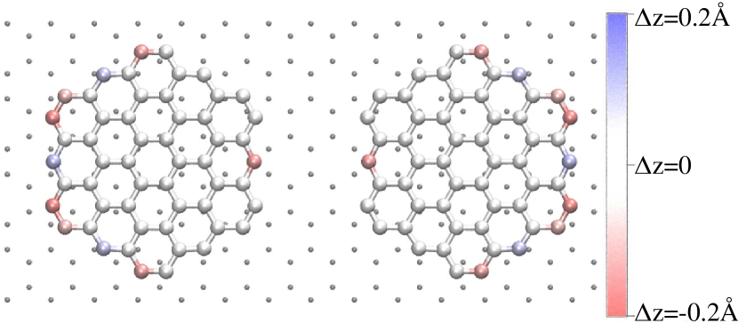
When we compare the average distance to the surface of the edge atoms, defined as the atoms with two neighbors, to that of the inner atoms (Figs. 7f and 7g), we see that the edge atoms are much closer to the surface and therefore contribute most to the load energy. While the inner atoms move nearly continuously also at higher loads, the edge atoms move discontinuously. The two configurations corresponding to the two minima in the period at nN are shown in Fig. 8. One can see that edge atoms on either side are much closer to the surface and the discontinuity of the motion corresponds in this case to a tilting of the flake in going from to and vice versa.
All examined flake sizes and scanlines which show a transition from smooth to stick-slip motion as a function of load, show a corresponding jump in the coordinates of the edge atoms. As the edge to surface ratio decreases with flake size, edge effects become less important for larger flakes. We indeed observe that the friction increases more, and from a lower load per atom, for smaller flakes, as shown in Fig. 4. That the increase in friction at incommensurate orientations is mostly due to edge effects makes friction very dependent on the details of the energy landscape and makes it difficult to draw general trends as a function of scanline, number of particles, and orientation with respect to the substrate. Depending on the scanline, there can be multiple minima or only one per period and the barriers between them can be high or low. For instance for the 96 atom flake, a marked increase of friction is observed for scanlines C and D whereas no or only a very small increase is found for scanlines A and B respectively. The increase also depends on the orientation of the flake. For less symmetric situations, like flakes with and , we do observe an increase in friction with load for all scanlines.
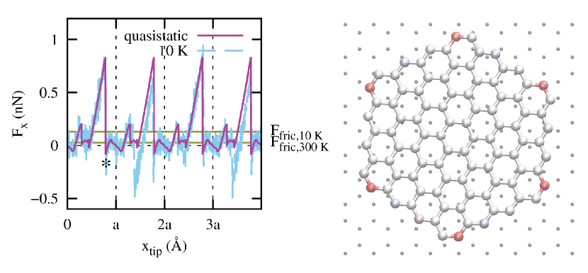
For the 96 atom flake along scanline C, we have also performed MD simulations. In Fig. 9 we see that at 10 K the flake displays the same stick-slip behavior found in the quasistatic approach. At room temperature however, the stick-slip motion is masked by large fluctuations of the lateral force, resulting in negligible friction. As the speed of nearly 5 m/s is several orders of magnitude higher than in experiments, these simulations are likely to underestimate the friction. The motion of the flake in the stick-slip regime is related to a very symmetric configuration of the flake with the six corner atoms locking into favorable positions of the substrate potential as shown in the right panel of Fig. 9.
In an experimental situation, it is likely that the undercoordinated atoms at the edge are saturated by Hydrogen. To investigate this situation, we have added Hydrogen atoms to the two-fold bonded edge atoms of the 54 atom flake. We model the H atoms as interacting with the flake and substrate atoms through the REBO potential and neglect interaction with the tip. The effect of Hydrogen on friction as a function of load for this flake along scanline D is shown by the line labeled ’H’ in figure 4. The behavior of friction is qualitatively the same but the increase starts at a higher load when Hydrogen is present. This fact might have been expected because the in-plane bonds are better preserved up to the edges, making the edges of the flake less flexible.
In addition to the effects studied here, elastic deformations of the substrate could also add to the total friction. The latter effect decreases with the number of layers of the substrateCarpick (2012); Tewary (2012). As we model a bulk graphite substrate, we have not included this in our model. However, elastic deformations could significantly contribute to the friction on few-layer graphene substrates.
IV Summary and conclusion
In summary, we have studied the motion and friction of mobile and flexible graphene flakes moving at incommensurate orientations on a graphite substrate. In agreement with FFM experimental results, we have found that the superlubric behavior at low loads evolves to a frictional stick-slip motion at high loads. This change is reversible since it is not due to rotations to commensurate orientations but rather to a locking of the flakes as a result of vertical motion of the edge atoms, also when H-saturation is considered. Interestingly no dislocations appear in the flake also under high load, contrary to the typical behavior of diffusion for metals and rare gas islands on surfaces. The strong in-plane bonding of layered materials like graphite makes that the crystalline structure is preserved while vertical distortions at the edges are energetically favorable. This feature might explain the good and persisting lubricant properties of layered materials.
V Acknowledgements
We thank Astrid de Wijn, Ted Janssen and Nicola Manini for useful discussions. This work is part of the research program of the Foundation for Fundamental Research on Matter (FOM), which is part of the Netherlands Organisation for Scientific Research (NWO).
References
- Novoselov et al. (2004) K. S. Novoselov, A. K. Geim, S. Morozov, D. Jiang, Y. Zhang, S. Dubonos, I. Grigorieva, and A. Firsov, Science 306, 666 (2004).
- Lebègue et al. (2013) S. Lebègue, T. Björkman, M. Klintenberg, R. M. Nieminen, and O. Eriksson, Phys. Rev. X 3, 031002 (2013).
- Mate et al. (1987) C. M. Mate, G. M. McClelland, R. Erlandsson, and S. Chiang, Phys. Rev. Lett. 59, 1942 (1987).
- Tomlinson (1929) G. Tomlinson, Phil. Mag. 7, 905 (1929).
- Prandtl (1928) L. Prandtl, Z. Angew. Math. Mech 8, 85 (1928).
- Hölscher et al. (1998) H. Hölscher, U. D. Schwarz, O. Zwörner, and R. Wiesendanger, Phys. Rev. B 57, 2477 (1998).
- Morita et al. (1996) S. Morita, S. Fujisawa, and Y. Sugawara, Surf. Sci. Rep. 23, 1 (1996).
- Sasaki et al. (1998) N. Sasaki, M. Tsukada, S. Fujisawa, Y. Sugawara, S. Morita, and K. Kobayashi, Phys. Rev. B 57, 3785 (1998).
- Dienwiebel et al. (2004) M. Dienwiebel, G. S. Verhoeven, N. Pradeep, J. W. M. Frenken, J. A. Heimberg, and H. W. Zandbergen, Phys. Rev. Lett. 92, 126101 (2004).
- Cruz-Silva et al. (2004) E. Cruz-Silva, X. Jia, H. Terrones, B. G. Sumpter, M. Terrones, M. S. Dresselhaus, and V. Meunier, ACS nano 7, 2834 (2013).
- Hirano and Shinjo (1993) M. Hirano and K. Shinjo, Wear 168, 121 (1993).
- Feng et al. (2013) X. Feng, S. Kwon, J. Y. Park, and M. Salmeron, ACS Nano 7, 1718 (2013).
- Shinjo and Hirano (1993) K. Shinjo and M. Hirano, Surf. Sci. 283, 473 (1993).
- Erdemir and Martin (2007) A. Erdemir and J.-M. Martin, Superlubricity (Elsevier, 2007).
- Gnecco et al. (2008) E. Gnecco, S. Maier, and E. Meyer, J. Phys.: Condens. Matter 20, 354004 (2008).
- van den Ende et al. (2012) J. A. van den Ende, A. S. de Wijn, and A. Fasolino, J. Phys.: Condens. Matter 24, 445009 (2012).
- Yang et al. (2013) J. Yang, Z. Liu, F. Grey, Z. Xu, X. Li, Y. Liu, M. Urbakh, Y. Cheng, and Q. Zheng, Phys. Rev. Lett. 110, 255504 (2013).
- Filippov et al. (2008) A. E. Filippov, M. Dienwiebel, J. W. M. Frenken, J. Klafter, and M. Urbakh, Phys. Rev. Lett. 100, 046102 (2008).
- de Wijn et al. (2010) A. S. de Wijn, C. Fusco, and A. Fasolino, Phys. Rev. E 81, 046105 (2010).
- Dienwiebel (2003) M. Dienwiebel, Ph.D. thesis, Leiden University (2003).
- Bonelli et al. (2009) F. Bonelli, N. Manini, E. Cadelano, and L. Colombo, Eur. Phys. J. B 70, 449 (2009).
- Kim and Falk (2009) W. K. Kim and M. L. Falk, Phys. Rev. B 80, 235428 (2009).
- Hamilton et al. (1995) J. C. Hamilton, M. S. Daw, and S. M. Foiles, Phys. Rev. Lett. 74, 2760 (1995).
- Stuart et al. (2000) S. Stuart, A. Tutein, and J. Harrison, J. Chem. Phys. 112, 6472 (2000).
- Brenner et al. (2002) D. Brenner, O. Shenderova, J. Harrison, S. Stuart, B. Ni, and S. Sinnott, J. Phys.: Condens. Matter 14, 783 (2002).
- Plimpton et al. (1995) S. Plimpton, J. Comput. Phys. 117, 1 (1995).
- Kolmogorov and Crespi (2005) A. N. Kolmogorov and V. H. Crespi, Phys. Rev. B 71, 235415 (2005).
- Reguzzoni et al. (2012) M. Reguzzoni, A. Fasolino, E. Molinari, and M. C. Righi, Phys. Rev. B 86, 245434 (2012).
- (29) A. Fasolino, in Handbook of theoretical and computational nanotechnology, edited by M. Rieth and W. Schommers (American Scientific Publishers, 2006).
- Verhoeven et al. (2004) G. S. Verhoeven, M. Dienwiebel, and J. W. M. Frenken, Phys. Rev. B 70, 165418 (2004).
- Bitzek et al. (2006) E. Bitzek, P. Koskinen, F. Gähler, M. Moseler, and P. Gumbsch, Phys. Rev. Lett. 97, 170201 (2006).
- Marchetto et al. (2012) D. Marchetto, C. Held, F. Hausen, F. Wählisch, M. Dienwiebel, and R. Bennewitz, Tribol. Lett. 48, 77 (2012).
- Peyrard and Aubry (1983) M. Peyrard and S. Aubry, J. Phys. C 16, 1593 (1983).
- Reguzzoni and Righi (2012) M. Reguzzoni and M. C. Righi, Phys. Rev. B 85, 201412 (2012).
- Carpick (2012) C. Lee, Q. Li, W. Kalb, X.-Z. Liu, H. Berger, R. W. Carpick, and J. Hone, Science 328, 76 (2010).
- (36) A. Smolyanitsky, J. P. Killgore, and V. K. Tewary, Phys. Rev. B 85, 035412 (2012).