Current induced torques in structures with ultra-thin IrMn antiferromagnet
Abstract
Relativistic current induced torques and devices utilizing antiferromagnets have been independently considered as two promising new directions in spintronics research. Here we report electrical measurements of the torques in structures comprising a nm thick layer of an antiferromagnet IrMn. We perform ac-electrical measurements in Ta/IrMn/CoFeB and Ta/IrMn structures below and above the Néel temperature of the ultra-thin IrMn and compare the results with control experiments in a Ta/CoFeB paramagnet/ferromagnet bilayer. The torques observed in CoFeB are consistent with the opposite sign of the spin Hall angle in Ta and IrMn. By combining temperature-dependent measurements in all three structures we conclude that torques act also in the antiferromagnetic IrMn at the interface with Ta.
pacs:
75.50.Ee,75.47.-m,85.80.JmSince the relativistic spin-orbit interaction couples electron’s momentum and spin it can lead to a range of effects when systems are brought out of equilibrium by applied electric fields. Non-equilibrium spin polarization phenomena may occur even in non-magnetic spin-orbit coupled conductors. A prime example is the spin Hall effect (SHE) in which an electrical current passing through a material with relativistic spin-orbit coupling generates a transverse spin-current polarized perpendicular to the plane defined by the charge and spin-current Sinova et al. (2015). The spin-current generated in a normal metal (NM) via the SHE can be absorbed in a ferromagnet (FM) and the spin angular momentum transferred to the magnetization. The corresponding relativistic spin torques are a candidate spintronic technology for a new generation of electrically-controlled spintronic devices Miron et al. (2011); Liu et al. (2012).
Unlike FMs, antiferromagnets (AFMs) have traditionally played only a static supporting role in spintronic devices by enhancing the magnetic hardness of the FM electrode via the interfacial exchange-bias effect Radu and Zabel (2008). More recently, AFM spintronic devices have been demonstrated, including magneto-resistors and memories Park et al. (2011); Wang et al. (2012); Marti et al. (2014); Fina et al. (2014), in which AFM electrodes play an active role in the device.
A key challenge in the field of AFM spintronics is to find efficient means for manipulating the compensated moments. Here the relativistic spin torques represent one of the promising routes Železný et al. (2014). In one picture, the torques occur in AFMs like Mn2Au or CuMnAs whose spin-sublattices of the bulk crystal structure form inversion partners Železný et al. (2014); Wadley et al. (2015).
In this paper we focus on an alternative scenario applying to AFMs of a general bulk crystal structure that are prepared in thin films and interfaced with a FM and/or a spin-orbit coupled NM. The SHE generated in the AFM Mendes et al. (2014); Zhang et al. (2014) can induce a torque on the adjacent FM Tshitoyan et al. (2015). Remarkably, theory also predicts Železný et al. (2014) that relativistic current-induced torques at the NM/AFM interface might provide an efficient mechanism for manipulating the AFM spins.
Our aim is to experimentally identify these phenomena by performing systematic ac-electrical measurements in a NM/AFM/FM trilayer, NM/AFM bilayer, and a control NM/FM bilayer, with the structures comprising Ta NM, IrMn AFM, and CoFeB FM films. The method we employ is based on utilizing ultra-thin ( nm) Ir0.2Mn0.8. The small thickness of the AFM film is favorable for detecting spin-torques generated at the NM/AFM interface. Moreover, the Néel temperature is suppressed from the bulk K Yamaoka (1974) to well below room-temperature Petti et al. (2013) in the ultra-thin IrMn. This allows us to compare the observed torques in both the NM/AFM and NM/AFM/FM stacks when IrMn is in the antiferromagnetic and paramagnetic phases and to confirm the magnetic origin of the current-induced effects observed in these structures.
We start with discussing our experiments in the NM/AFM/FM trilayer. The layers were deposited by UHV RF magnetron sputtering on a thermally oxidized Si substrate (700 nm SiO2 on (001) Si) at a base pressure of 10-9 Torr and in a magnetic field of 5 mT. To achieve high crystal and magnetic quality of the films, the wafers were annealed at 350∘C for 1 hour in a 10-6 Torr vacuum in a magnetic field of 0.6 T applied along the sample edge Hayakawa et al. (2005). (For more details see the Supplementary information sup .) From simulations of the X-ray reflectivity data sup we obtain the following structure: Ta()/IrMn()/CoFeB()/MgO() capped with 10 nm of Al2O3. The numbers in brackets correspond to the layer thicknesses in nm and are consistent with the nominal growth values.
Magnetic measurements shown in Fig. 1(a) were performed by the superconducting quantum interference device (SQUID). Exchange coupling at low temperatures between the IrMn AFM and the CoFeB FM is confirmed by the shift and broadening of the hysteresis loop when cooling the sample from 400 K to 5 K in a magnetic field of T applied along the field direction used during annealing. Note that the low-temperature exchange bias is weak and positive, consistent with the small thickness of our IrMn film and with previous studies of IrMn/CoFeB interfaces Raju et al. (2013). Consistent with the expected high-temperature paramagnetic phase of our ultra-thin IrMn, the sample shows no shift and broadening of the hysteresis loop when field-cooled to 200 K.
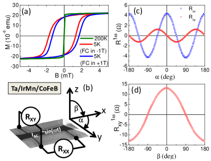
The device geometry is shown in Fig. 1(b). The Hall bar width is 2 m and the distance between longitudinal contacts is 7 m sup . In electrical measurements, the Hall bar is biased by a low frequency (123 Hz) ac current applied along the x-axis. We use lock-in amplifiers to measure simultaneously first harmonic (1) and second harmonic (2) signals Pi et al. (2010); Garello et al. (2013); Kim et al. (2013). Examples of the first harmonic signals are shown in Figs.1(c),(d) where angles and correspond to in-plane () and out-of-plane () magnetization rotation, respectively. The relative amplitudes of the longitudinal and transverse anisotropic magnetoresistance (AMR) seen in Fig.1(c) are consistent with the aspect ratio of the longitudinal and transverse dimensions of the Hall bar. When rotating the magnetization out-of-plane, the signal is dominated by the anomalous Hall effect (AHE), as seen in Fig.1(d).
Current induced torques contribute to the higher-harmonic non-ohmic components of the resistance. In our study we focus on the second harmonic signals. For a systematic set of measured first and second harmonic transport signals, including also experiments for magnetization rotation in the plane and magnetic-sweep measurements, we refer to the Supplementary information sup .
Examples of and for the in-plane rotation of magnetization are shown in Fig. 2. Two types of torques can be expected in our structure: The antidamping-like torque which for magnetization rotating in the plane is driven by an out-of-plane effective field , and the field-like torque due to an in-plane field . Neither of these fields would generate via the AMR a signal (see Tab. S1 in the Supplementary information sup ) that is seen in Figs. 2 (a)-(c) for the Ta/IrMn/CoFeB sample at high and low temperatures and also for the control Ta/CoFeB sample.
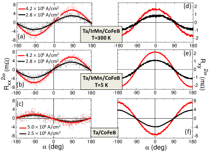
A mechanism that can consistently explain the angular dependence of seen in Figs. 2(a)-(c) is the longitudinal spin Seebeck effect (SSE) sup . The SSE is generated by an out-of-plane thermal gradient. It drives a spin current from the FM into the adjacent layer and here the inverse SHE converts the spin current into an electrical voltage along the in-plane direction perpendicular to the magnetization in the FM Kikkawa et al. (2013). While not detecting the spin torque itself in , the data provide us, nevertheless, with a valuable information on the SHE which can generate the current-induced spin torque. Signatures of the spin torque will be identified below in the discussion of the signals.
Earlier studies found opposite sign of spin Hall angles in IrMn and Ta Liu et al. (2012); Mendes et al. (2014); Zhang et al. (2014) which is consistent with the measured opposite sign of the in the Ta/IrMn/CoFeB and the Ta/CoFeB samples and confirms that these longitudinal signals can originate from the SSE. Thermal effects generated by Joule heating are quadratic in the driving current and can, therefore, contribute to the second harmonic signals for the biasing current . Consistent with the data in Figs. 2(a)-(c), the signals due to the SSE scale with the current amplitude since the thermally generated voltage is quadratic in and the resistances plotted in Figs. 2(a)-(c) are obtained by dividing the voltages by .
The observed SSE signals are independent of the base temperature. In the transport experiments, the vertical thermal gradient across the IrMn/CoFeB bilayer (or the control Ta/CoFeB bilayer) is determined by the gradient in the resistivity across the bilayer. Since the dependence of the resistivity on base temperature is negligible in the studied temperature range (see Fig. S3 in the Supplementary information sup ), the Joule heating gradient across the metal films can be also expected to be independent of the base temperature. From this we conclude, that the inverse SHE in IrMn does not change significantly between the low-temperature AFM phase and the high-temperature paramagnetic phase.
The SSE contributes to the transverse resistance as (see Tab. S2 in the Supplementary information sup ). This angular dependence is observed in Figs. 2(d)-(f). However, when comparing in Figs. 2(a) and (d) the amplitudes of and signals for the Ta/CoFeB sample they do not scale with the Hall bar aspect ratio. As in a number of previous studies of NM/FM bilayers, the additional signal is attributed to the current-induced antidamping-like torque acting in CoFeB. The corresponding out-of-plane effective field can originate form the spin-current polarized along the y-axis which is generated by the SHE in Ta and absorbed in the CoFeB FM. The symmetry reflects the ouf-of-plane tilt of the magnetization due to the current-induced effective out-of-plane field which is sensed electrically via the AHE in CoFeB sup .
In the Ta/IrMn/CoFeB sample the signal due to the antidamping-like torque is detected at low temperatures. In the high-temperature paramagnetic phase of IrMn the amplitudes of -dependent and signals scale with the Hall bar aspect ratio, implying that the SSE dominates and the current induced torque is diminished.
In Fig. 3 we summarize the low and high-temperature measurements in the Ta/IrMn/CoFeB sample and compare with the temperature-independent results in the control Ta/CoFeB sample. After subtracting the SSE contribution, the remaining component due to the antidamping-like torque is recalculated into the magnitude of the effective current-induced out-of-plane field. For this we used the calibration of the first harmonic AHE signal in an externally applied out-of-plane magnetic field (for more details see Supplementary text below Tab. S2 sup ). Similar to the SEE signal, scales linearly with the density of the driving ac current since the generated changes in the magnetization direction are small and AHE varies linearly in this small tilt regime.
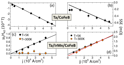
Fig. 3 highlights the SHE origin of which, as in the SSE case, changes sign when CoFeB is interfaced with either Ta or IrMn. The inferred spin Hall angle in the Ta layer from measurements in the Ta/CoFeB bilayer is . The effective spin Hall angle recalculated to the current flowing in the IrMn layer of the Ta/IrMn/CoFeB stack at 5 K is .
We point out that the SSE and the antidamping-like spin torque, as well as the inferred magnitudes of and the spin Hall angles, were confirmed by performing magnetization rotation experiments in all three orthogonal planes. The measured transport signals were systematically decomposed into harmonic functions of the magnetization rotation angles. The technique is described in detail in the Supplementary material sup .
We also remark that angular-dependent components with a symmetry corresponding to the field-like torque were not identified in the measured data. One source of the field-like torque is the Oersted field which in our experiments does not exceed 0.1 mT. In data shown in Figs. 2(a)-(c), e.g., the corresponding term sup would contribute via AMR with an amplitude below , i.e., within the noise in Figs. 2(a)-(c).
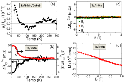
As noted above, when the spin-current is injected from the CoFeB FM via the SSE and converted into the electrical signal by the inverse SHE in IrMn, the effect is only weakly temperature dependent. From this it might look surprising that the antidamping-like torque generated by the SHE is sizable only in the low-temperature antiferromagnetic phase of IrMn while at higher temperatures it is suppressed and fluctuates around zero, as summarized in Fig. 4(a). Our trilayer is, however, not inversion symmetric and the broken reciprocity between the SSE and the current-induced torque at higher temperatures can be reconciled as follows:
In the SSE the spin-current is generated in the CoFeB and converted via the inverse SHE to the charge signal primarily in the IrMn layer underneath. In the current-induced torque, on the other hand, the spin-current is generated by the SHE in the Ta/IrMn bilayer. Since the spin Hall angles are opposite in Ta and IrMn, the contributions from the two layers tend to compensate, resulting, at high temperatures, in a small net torque in CoFeB fluctuating around zero.
At low temperatures when IrMn is antiferromagnetic the behavior changes. The torque in CoFeB becomes sizable and, considering its sign, it is dominated by the IrMn SHE. The effect of the SHE spin-current from Ta on CoFeB moments is diminished. From experiments in the control Ta/CoFeB sample we observed that the SHE in Ta is temperature independent over the whole studied temperature range. Combining all these indications we arrive at a conclusion that the SHE spin-current from Ta is absorbed at low temperatures by the AFM moments in IrMn.
Note the for the CoFeB and IrMn films strongly coupled at low temperatures the above scenario should be extended to account for the CoFeB/IrMn bilayer behaving as one joint magnetic medium. The calibration from first-harmonic resistances in external magnetic field then describes effective magneto-transport coefficients of the coupled bilayer. Similarly, inferred from the second-harmonic resistances represents an effective current-induced field acting on the CoFeB/IrMn bilayer which can have contributions from torques generated at the Ta/IrMn and IrMn/CoFeB interfaces. The same applies to the spin Hall angle obtained form and normalized to the current flowing through IrMn which parametrizes the entire NM/AFM/FM trilayer rather than the SHE of IrMn alone.
In either of the detailed versions of the above scenario, the current-induced torque in the AFM plays a central role. To independently identify this effect we performed measurements in the Ta/IrMn structure comprising no FM layer. Since the IrMn moments in the low-temperature AFM phase cannot be manipulated by the applied magnetic field we use a procedure in which magnetic field is applied at different angles while cooling the Ta/IrMn sample from room-temperature. In earlier studies of similar thin IrMn films embedded in tunnel junctions, the field-cooling procedure enabled us to define states showing distinct magnetoresistance signals at low temperatures Petti et al. (2013). These distinct states of the AFM IrMn then remained insensitive to the applied magnetic field when staying sufficiently below the Néel temperature Petti et al. (2013).
Analogous behavior of our Hall bar device is illustrated in Fig. 4(b). Here the sample was first cooled from 300 K to 5 K in an applied in-plane magnetic field of 2 T and then the experiment was repeated with field-cooling in a 2 T out-of-plane field. A clear onset of a non-zero difference between the two field-cool measurements is observed in the first harmonic resistance signal at K. This is consistent with the expected transition into the AFM phase in the thin IrMn film. It coincides with the observed enhancement of at low temperatures in the Ta/IrMn/CoFeB stack which we also associated with the paramagnetic to AFM transition in IrMn (see Fig. 4(a)). Remarkably, the onset of in the Ta/IrMn bilayer is accompanied by the onset of the second harmonic , suggesting that these signals are of magnetic origin and that the magnetic moments are torqued in the AFM by the applied current.
To confirm that the signals in Fig. 4(b) are due to the AFM moments we show in Fig. 4(c) the second harmonic signal while sweeping the external magnetic field between T and keeping the temperature at 5K. Similar to the first harmonic magnetoresistance, the second harmonic becomes completely insensitive to the strong magnetic fields in the low-temperature AFM phase of IrMn. Low-temperature magnetization data plotted in Fig. 4(d), showing only a diamagnetic signal of the substrate, provide an additional confirmation of the low-temperature AFM phase of IrMn and of the absence of a FM component in the stack.
We conclude by recalling that theoretical studies have predicted relativistic current-induced torques in bulk AFMs as well as at interfaces Železný et al. (2014). The bulk effects require specific symmetries of the crystal and magnetic structures of the AFM material and have been recently identified in current-induced switching experiments in CuMnAs Wadley et al. (2015). The AFM torques acting at interfaces are expected to be more generic regarding the symmetries of the AFM unit cell. Our AFM-torque interpretation of the non-ohmic transport signals in the Ta/IrMn bilayer is consistent with these theory predictions for AFM interfaces. Independently, the SHE spin-current from Ta absorbed via the AFM torque in IrMn consistently fits into the overall picture obtained from the complementary measurements in the Ta/IrMn, Ta/IrMn/CoFeB and Ta/CoFeB structures. Our results open the prospect for using current induced torques in transition metal multilayers to manipulate moments in AFMs.
We acknowledge support from the EU European Research Council (ERC) advanced grant no. 268066, from the Marie Curie Initial Training Network grant no. 316657, from the Ministry of Education of the Czech Republic grant no. LM2011026, from the Grant Agency of the Czech Republic grant no. 14-37427G, and from the Austrian Science Fund (FWF): J3523-N27.
References
- Sinova et al. (2015) J. Sinova, S. O. Valenzuela, J. Wunderlich, C. H. Back, and T. Jungwirth, Rev. Mod. Phys., in press (2015), arXiv:1411.3249v1 .
- Miron et al. (2011) I. M. Miron, K. Garello, G. Gaudin, P.-J. Zermatten, M. V. Costache, S. Auffret, S. Bandiera, B. Rodmacq, A. Schuhl, and P. Gambardella, Nature 476, 189 (2011).
- Liu et al. (2012) L. Liu, C.-F. Pai, Y. Li, H. W. Tseng, D. C. Ralph, and R. A. Buhrman, Science 336, 555 (2012).
- Radu and Zabel (2008) F. Radu and H. Zabel, Springer Tracts Mod. Phys. 227, 97 (2008).
- Park et al. (2011) B. G. Park, J. Wunderlich, X. Martí, V. Holý, Y. Kurosaki, M. Yamada, H. Yamamoto, A. Nishide, J. Hayakawa, H. Takahashi, A. B. Shick, and T. Jungwirth, Nat. Mater. 10, 347 (2011).
- Wang et al. (2012) Y. Y. Wang, C. Song, B. Cui, G. Y. Wang, F. Zeng, and F. Pan, Phys. Rev. Lett. 109, 137201 (2012).
- Marti et al. (2014) X. Marti, I. Fina, C. Frontera, J. Liu, P. Wadley, Q. He, R. J. Paull, J. D. Clarkson, J. Kudrnovský, I. Turek, J. Kuneš, D. Yi, J.-H. Chu, C. T. Nelson, L. You, E. Arenholz, S. Salahuddin, J. Fontcuberta, T. Jungwirth, and R. Ramesh, Nat. Mater. 13, 367 (2014).
- Fina et al. (2014) I. Fina, X. Marti, D. Yi, J. Liu, J. H. Chu, C. Rayan-Serrao, S. Suresha, a. B. Shick, J. Zelezný, T. Jungwirth, J. Fontcuberta, and R. Ramesh, Nat. Commun. 5, 4671 (2014).
- Železný et al. (2014) J. Železný, H. Gao, K. Výborný, J. Zemen, J. Mašek, A. Manchon, J. Wunderlich, J. Sinova, and T. Jungwirth, Phys. Rev. Lett. 113, 157201 (2014).
- Wadley et al. (2015) P. Wadley, B. Howells, J. Zelezny, C. Andrews, V. Hills, R. P. Campion, F. Freimuth, Y. Mokrousov, A. W. Rushforth, K. W. Edmonds, and B. L. Gallagher, (2015) .
- Mendes et al. (2014) J. B. S. Mendes, R. O. Cunha, O. Alves Santos, P. R. T. Ribeiro, F. L. a. Machado, R. L. Rodríguez-Suárez, A. Azevedo, and S. M. Rezende, Phys. Rev. B 89, 140406 (2014).
- Zhang et al. (2014) W. Zhang, M. B. Jungfleisch, W. Jiang, J. E. Pearson, A. Hoffmann, F. Freimuth, and Y. Mokrousov, Phys. Rev. Lett. 113, 196602 (2014).
- Tshitoyan et al. (2015) V. Tshitoyan, C. Ciccarelli, A. P. Mihai, M. Ali, A. Irvine, T. A. Moore, T. Jungwirth, and A. J. Ferguson, (2015), arXiv:1502.04570 .
- Yamaoka (1974) T. Yamaoka, J. Phys. Soc. Japan 36, 445 (1974).
- Petti et al. (2013) D. Petti, E. Albisetti, H. Reichlová, J. Gazquez, M. Varela, M. Molina-Ruiz, a. F. Lopeandía, K. Olejník, V. Novák, I. Fina, B. Dkhil, J. Hayakawa, X. Marti, J. Wunderlich, T. Jungwirth, and R. Bertacco, Appl. Phys. Lett. 102, 192404 (2013).
- Hayakawa et al. (2005) J. Hayakawa, S. Ikeda, F. Matsukura, H. Takahashi, and H. Ohno, Japanese J. Appl. Physics, Part 2 Lett. 44, 2 (2005) .
- (17) See supplementary material at http://link.aps.org/ 4 supplemental/10.1103/PhysRevLett.000.000000 for brief description.
- Raju et al. (2013) M. Raju, S. Chaudhary, and D. K. Pandya, Eur. Phys. J. B 86 , 491 (2013) .
- Pi et al. (2010) U. H. Pi, K. Won Kim, J. Y. Bae, S. C. Lee, Y. J. Cho, K. S. Kim, and S. Seo, Appl. Phys. Lett. 97, 162507 (2010).
- Garello et al. (2013) K. Garello, I. M. Miron, C. O. Avci, F. Freimuth, Y. Mokrousov, S. Blügel, S. Auffret, O. Boulle, G. Gaudin, and P. Gambardella, Nat. Nanotechnol. 8, 587 (2013).
- Kim et al. (2013) J. Kim, J. Sinha, M. Hayashi, M. Yamanouchi, S. Fukami, T. Suzuki, S. Mitani, and H. Ohno, Nat. Mater. 12, 240 (2013).
- Kikkawa et al. (2013) T. Kikkawa, K. Uchida, S. Daimon, Y. Shiomi, H. Adachi, Z. Qiu, D. Hou, X.-F. Jin, S. Maekawa, and E. Saitoh, Phys. Rev. B 88, 214403 (2013).