Universal quantum gates on electron-spin qubits with quantum dots inside single-side optical microcavities111Published in Opt. Express 22, 593-607 (2014)
Abstract
We present some compact quantum circuits for a deterministic quantum computing on electron-spin qubits assisted by quantum dots inside single-side optical microcavities, including the CNOT, Toffoli, and Fredkin gates. They are constructed by exploiting the giant optical Faraday rotation induced by a single-electron spin in a quantum dot inside a single-side optical microcavity as a result of cavity quantum electrodynamics. Our universal quantum gates have some advantages. First, all the gates are accomplished with a success probability of 100% in principle. Second, our schemes require no additional electron-spin qubits and they are achieved by some input-output processes of a single photon. Third, our circuits for these gates are simple and economic. Moreover, our devices for these gates work in both the weak coupling and the strong coupling regimes, and they are feasible in experiment.
pacs:
03.67.Lx, 42.50.Ex, 42.50.Pq, 78.67.HcI Introduction
In quantum computing, a quantum algorithm is usually realized by a sequence of quantum gates book . Constructing compact quantum gates is crucial for building a quantum computer. It has been proven that any quantum entangling gate supplementing with single-qubit gates can implement a universal quantum computing uni . The controlled-not (CNOT) gate is a universal two-qubit gate and it attracts much attention. As for multi-qubit quantum systems, attention was mainly focused on the three-qubit Toffoli and Fredkin gates as they can be used to implement any multi-qubit quantum computing with Hadamard gates Toffoli ; Fredkin .
Up to now, many important proposals have been proposed for physically implementing quantum gates longpra ; Tongprl ; longprl . For example, in 2001, Knill et al. photon1 proposed a probabilistic scheme for implementing a CNOT gate on two photonic qubits by using linear optical elements, additional photons, and postselection. Based on cross-Kerr nonlinearity or charge detection, Nemoto et al. photon5 , Lin et al. photon9 , and Beenakker et al. MoveCNOT provided some interesting proposals for a deterministic quantum computing. In these schemes, some additional qubits are employed. A strong cross-Kerr nonlinearity is still a big challenge in experiment at present. To achieve a nontrivial nonlinearity between two individual qubits for a deterministic quantum computation with the present experimental techniques, an appealing platform for quantum information processing with an artificial atom and a cavity is proposed Hu1 ; Hu2 .
A quantum system combining a cavity and an artificial atom, such as a quantum dot (QD), a superconducting qubit, or a diamond nitrogen-vacancy center, is a perfect platform for quantum information processing because of its long coherence time and its good scalability. By utilizing such a platform, some interesting schemes were proposed for implementing the quantum gates on hybrid photon-matter systems Hu1 ; Hu2 ; Hybrid1 ; Hybrid2 . Based on the QD-cavity platform, a scalable deterministic quantum computation on photonic qubits photoncomput1 ; photoncomput2 ; photoncomput3 and a deterministic photonic spatial-polarization hyper-CNOT gate HyperCNOT were proposed recently. The quantum circuits for the universal gates on superconducting qubits Super1 ; Super5 or diamond nitrogen-vacancy center qubits NV1 ; NV2 ; NV3 assisted by optical microcavities were designed as well. Constructing universal quantum gates compactly can reduce the quantum resource needed and their errors.
A QD system is one of the promising candidates for quantum information processing and quantum state storage in solid-state quantum systems. The coherence time of a QD can be extended to s by using spin echo techniques cohertime1 ; cohertime2 ; cohertime3 . The single QD spin manipulation which is crucial for the implementation of single-qubit gates, can be achieved by using pulsed magnetic resonance techniques, nanosecond microwave pulses, or picosecond/femtosecond optical pulses spin-manipulate1 ; spin-manipulate2 ; spin-manipulate3 . Due to the external magnetic field and the short dephasing time, the magnetic resonance techniques are not compatible with our work. In our work, the rotation on the electron-spin qubit around the optical axis can be achieved by using a single photon, and the rotation can be achieved by using a single photon which interacts with the QD twice Hu4 .
In this paper, we present some compact quantum circuits for a universal quantum computing on an electron-spin system assisted by the QDs inside single-side optical microcavities. Based on the giant circular birefringence induced by a QD-cavity system as a result of cavity quantum electrodynamics Hu1 ; Hu2 , we construct the CNOT, Toffoli, and Fredkin gates on a stationary electron-spin system, achieved by some input-output processes of a single photon. Our schemes are simple and economic. They are accomplished with a success probability of 100% in principle and they do not require the additional electron-spin qubits which are employed in photon5 ; photon9 ; MoveCNOT . Our circuits for implementing the CNOT and Toffoli gates are especially compact. The electron qubits involved in these gates are stationary, which reduces the interaction between the spins and their environments, different from MoveCNOT . Moreover, our quantum circuits for the Toffoli and Fredkin gates beat their synthesis with two-qubit entangling gates and single-qubit gates largely. With current technology, these universal solid-state quantum gates are feasible.
II Compact quantum circuit for a CNOT gate on a stationary electron-spin system
II.1 A singly charged quantum dot in a single-side optical resonant microcavity
Figure 1 depicts the single-side QD-cavity system used in our schemes, i.e., a self-assembled In(Ga)As QD or a GaAs interface QD embedded in an optical resonant microcavity with one mirror partially reflective and the another one 100% reflective Hu1 ; Hu2 . According to Pauli’s exclusion principle, a negatively charged exciton () consisting of two electrons bound to one hole can be optically excited when an excess electron is injected into the QD HyperCNOT . In Fig. 1, and represent the spins of the excess electron with the angular momentum projections and along the cavity axis, respectively. and represent the hole-spin states with and , respectively. and present the right-circularly polarized photon and the left-circularly polarized photon, respectively. In 2008, Hu et al. Hu1 ; Hu2 showed that the L-polarized photon () drives transform into and the R-polarized photon () drives transform into , respectively, due to Pauli’s exclusion principle. The coupled -polarized (-polarized) photon and the uncoupled -polarized (-polarized) photon acquire different phases and amplitudes when they are reflected by the cavity. The reflection coefficient
| (1) |
can be obtain by solving the Heisenberg equations of the motion for the cavity mode and the dipole operation driven by the input field , and combing the relation between the input field and the output field in the weak excitation approximation Heisenberg
| (2) |
Here and are the frequencies of the cavity mode and the input single photon, respectively. is the frequency of the dipole transition of the negatively charged exciton . is the coupling strength between the cavity mode and . and are the decay rate and the side leakage rate of the cavity field, respectively. represents the decay rate of . and are the noise operators related to the reservoirs.
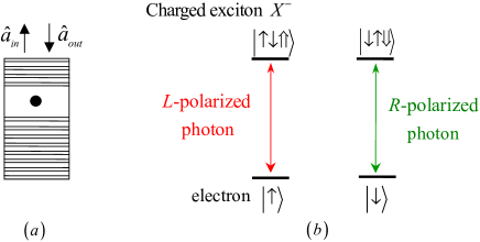
Hu et al. Hu1 ; Hu2 showed that for all if . If and , one can see that when . Here and are given by Eq. (1) with and , respectively. When is negligible, the transformations induced by the interaction between the QD and the input single photon can be expressed as follows:
| (3) |
Here and . We consider the case that the QD is resonant with the cavity mode and it interacts with the resonant single photon (i.e., ) in the conditions and below. In this case, and . That is, . The rules of the input states changing under the interaction of the photon and the cavity can be summarized as follows:
| (4) |
In 2011, Young et al. Hu6 measured the macroscopic phase shift of the reflected photon from a single-side pillar microcavity induced by a single QD in experiment. In a realistic cavity system, although it is hard to achieve the phase shift due to the side leakage and the cavity loss hard , the phase shift can be actually achieved in a QD-single-side-cavity system and it has been demonstrated by Hu’s group Hu4 . When , the phase shift can be achieved; otherwise, it cannot be achieved. The phase shift in our schemes can be achieved by a single photon which interacts with the QD twice. The above model works for a general polarization-degenerate cavity mode, including the micropillar unpolarized-pillar1 ; unpolarized-pillar2 ; unpolarized-pillar3 , H1 photonic crystal unpolarized-photon1 ; unpolarized-photon2 , and fiber-based fiber-based cavities.
Utilizing the optical circular birefringence induced by cavity quantum electrodynamics, the QD-cavity platform has been used to generate the maximally entangled states Hu1 ; Hu2 ; Hu3 ; Hu4 ; Hu5 ; Ren , construct the conditional phase gate on hybrid photon-QD systems Hu1 ; Hu2 , and design the hyper-CNOT gate on photonic qubits HyperCNOT . Based on the double-side one Hu3 , some universal quantum gates on photonic qubits photoncomput1 ; photoncomput2 and hybrid photon-QD systems Hybrid2 have been proposed. In 2011, Wang et al. repeater proposed a scheme for implementing a quantum repeater, resorting to the QDs in double-side cavities. In the following, we discuss the implementation of a deterministic quantum computing with QD-single-side-cavity systems, shown in Fig. 1. The QD-double-side-cavity system is robust to the transmission and the reflection coefficients, while the side leakage rate of the QD-single-side-cavity system is lower than the double-side one.
II.2 Compact circuit for a CNOT gate on a stationary electron-spin system
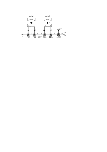
The principle for implementing a CNOT gate on the two stationary electron-spin qubits in the QDs confined in single-side resonant optical microcavities is shown in Fig. 2. It flips the state of the target qubit when the control qubit is in the state . Suppose the input state of the quantum system composed of the control and the target qubits (confined in the cavities 1 and 2, respectively) are initially prepared as
| (5) |
Here . The input single photon is prepared in the equal polarization superposition state .
Let us introduce the principle of our deterministic CNOT gate on two stationary electron-spin qubits. As depicted in Fig. 2, a single photon is injected into the input port , and its -polarized component is transmitted to the spatial model 1 by the polarizing beam splitter PBS1 and then arrives at PBS2 directly, while its -polarized component is reflected to the spatial model 2 for interacting with the QD inside the cavity 1. After the photon emitting from the spatial models 1 and 3 arrives at PBS2 simultaneously, a Hadamard operation is performed on it. That is, we let the photon pass through the half-wave plate (HWP) oriented at 22.5∘, which results in the transformations as follows:
| (6) |
Before and after the photon passes through the block composed of PBS3, the QD inside the cavity 2, and PBS4, a Hadamard operation is performed on the electron spin in the QD inside the cavity 2, respectively. Here completes the transformations as follows:
| (7) |
The evolution of the whole system composed of a single-photon medium and the QDs inside the cavities 1 and 2 induced by the above operations ( cavity 1 HWP ) can be described as follows:
| (8) |
Here and below, we use () to denote the photon in the state () emitting from the spatial mode and use to denote a Hadamard operation performed on the -th QD-spin qubit.
Next, the single photon is measured in the basis by the detectors and . From Eq. (8), one can see that the response of the detector indicates that the CNOT gate on the two electron-spin qubits succeeds; if the detector is clicked, after we perform a classical feed-forward operation on the control qubit, the CNOT gate is accomplished as well. That is, the output state of the system composed of the control and the target qubits confined in the cavities 1 and 2 becomes
| (9) |
The quantum circuit shown in Fig. 2 can be used to implement a CNOT gate on the two-qubit electron-spin system in a deterministic way, which implements a not operation on the target qubit if and only if (iff) the control qubit is in the state .
III Compact quantum circuit for a Toffoli gate on three electron-spin qubits in QDs
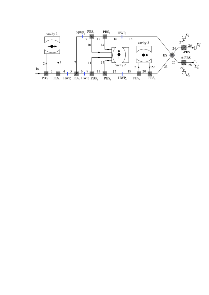
The principle for implementing a Toffoli gate on a three-qubit electron-spin system is shown in Fig. 3. It is used to flip the state of the target qubit iff both the two control qubits are in the state . Suppose the quantum system, which is composed of the three independent excess electrons inside the cavities 1, 2, and 3 that act as the first control qubit, the second control qubit, and the target qubit, respectively, is initially prepared in an arbitrary state
| (10) |
Here .
Next, we will specify the evolution of the system from the input state to the output state for characterizing the performance of our Toffoli gate. As illustrated in Fig. 3, our scheme for a Toffoli gate on a three-qubit electron-spin system can be achieved with four steps.
First, an input single photon in the state goes through the block composed of PBS1, the QD inside the cavity 1, and PBS2, and then an is performed on it (i.e., let the photon go though HWP1). Based on the argument as made in Sec. II.2, one can see that the above operations () transform the state of the complicated system composed of the single photon and the three QD-spin qubits from into . Here
| (11) | |||||
Second, PBS3 transforms and into and , respectively. Before and after the component () of the photon goes through the block composed of PBS4, the QD inside the cavity 2, and PBS6 (PBS5, the QD inside the cavity 2, and PBS7), an is performed on it with HWP2 and HWP4 (HWP3 and HWP5). The operations ( and ) transform the state of the complicated system into
| (12) | |||||
Third, before and after the photon goes through the block composed of PBS8, the QD inside the cavity 3, and PBS9 when it emits from the spatial model 19, an is performed on the electron spin in the QD inside the cavity 3, respectively. These operations () complete the transformation
| (13) | |||||
Subsequently, the wave packet emitting from the spatial model 23 arrives at the 50:50 beam splitter (BS) with the wave packet emitting from the spatial model 18 simultaneously.
Fourth, the balanced BS, which completes the transformations
| (14) |
transforms into the state
| (15) | |||||
According to the outcomes of the measurement on the single photon in the basis , we perform the appropriate single-qubit operations on the qubits shown in Table 1, and then the state of the solid-state quantum system composed of the three electron-spin qubits becomes
| (16) | |||||
From Eqs. (III) and (16), one can see that the evolution is accomplished. That is, the quantum circuit shown in Fig. 3 implements a Toffoli gate on the three stationary electron-spin qubits in QDs, and it flips the state of the target qubit inside the cavity 3 iff both the two control qubits inside the cavities 1 and 2, respectively, are in the state with a successful probability of 100% in principle.
| Feed-forward | |||
|---|---|---|---|
| photon | qubit | qubit | qubit |
IV Compact quantum circuit for a Fredkin gate on a three-qubit electron-spin system
Figure 4 depicts the principle of our scheme for implementing a Fredkin gate on a three-qubit electron-spin system assisted by the QDs inside single-side optical microcavities, which swaps the states of the two target qubits iff the control qubit is in the state . Suppose the input state of the system composed of the control qubit, the first target qubit, and the second target qubit inside the cavities 1, 2, and 3, respectively, is initially prepared as
| (17) | |||||
Here . The input single photon is prepared in the state .
Let us now describe the principle of our scheme for implementing a Fredkin gate on the three stationary electron-spin qubits in QDs in detail.
First, based on the argument as made in Sec. III, after the input photon goes through the block composed of PBS1, the QD inside the cavity 1, and PBS2, an (i.e., let it go through HWP1) is performed on it, and then the state of the whole system composed of the single photon and the three electron-spin qubits in the QDs confined in the cavities 1, 2, and 3 is transformed from into by the above operations (). Here
| (18) | |||||
Second, PBS3 transforms and into and , respectively. When the photon is in the state , before and after it goes through the block composed of PBS5, the QDs inside the cavities 2 and 3, and PBS7, an is performed on it with HWP3 and HWP5, respectively, and then it arrives at the balanced BS directly. When the photon is in the state , after an is performed on it with HWP2, the optical switch leads it to the block composed of PBS4, the QDs inside the cavities 2 and 3, and PBS6, following with an which is performed on the photon with a wave plate (WP) and a mirror. Here and . These operations ( and ) complete the transformation
| (19) | |||||
Third, the photon emitting from the spatial model 20 is injected into the block composed of PBS6, the QDs inside the cavities 2 and 3, and PBS4 again, and before and after the photon interacts with the QDs inside the cavities 3 and 2, an is performed on the QDs inside the cavities 3 and 2, respectively. The optical switch leads the wave packet to the spatial model 21 for interfering with the wave packet emitting from the spatial model 22. The above operations () complete the transformation
| (20) | |||||
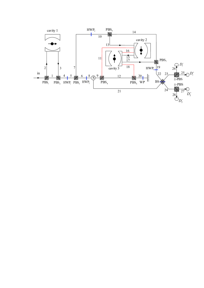
Fourth, the single photon is detected by the detectors in the basis after the 50:50 BS transforms into . Here
| (21) | |||||
Fifth, according to the outcomes of the measurement on the output single photon, we perform some appropriate classical feed-forward single-qubit operations, shown in Table 2, on the electron-spin qubits to make the state of the system composed of the three electrons inside the cavities 1, 2, and 3 to be
| (22) | |||||
From Eqs. (IV) and (22), one can see that the evolution is completed. That is, the quantum circuit shown in Fig. 4 implements a Fredkin gate on the three-qubit electron-spin system in a deterministic way, which swaps the states of the two target qubits iff the state of the control qubit is in the state .
| Feed-forward | |||
|---|---|---|---|
| photon | qubit | qubit | qubit |
V The feasibilities and efficiencies of our schemes
So far, all the procedures in our schemes for the three universal quantum gates are described in the case that the side leakage rate is negligible. To present our ideas more realistically, should be taken into account. In this time, the rules of the input states changing under the interaction of the photon and the cavity become
| (23) |
The fidelities and the efficiencies of the universal quantum gates are sensitive to as influences the amplitudes of the reflected photon (see Eq. (1)). Here the fidelity of a quantum gate is defined as
| (24) |
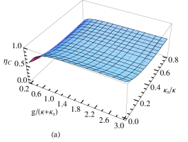
where is the output state of the system composed of the QD-spin qubits involved in the gate and a single-photon medium in the ideal case (that is, the photon escapes through the input-output mode). is the output state of the complicated system in the realistic case (that is, the cavities are imperfect and the side leakage is taken into account). The efficiency of the gate is considered as
| (25) |
Here and are the numbers of the input photons and the output photons, respectively.
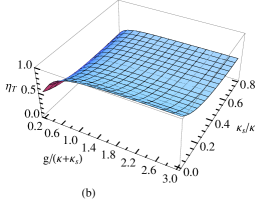
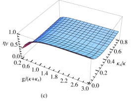
For perfect cavities, the fidelities of our universal quantum gates can reach unity. By considering the side leakage and combining the specific processes of the construction for the universal quantum gates discussed above, the fidelities of our CNOT gate , Toffoli gate , and Fredkin gate , and their efficiencies , , and can be calculated as follows:
| (26) |
| (27) | |||||
| (28) | |||||
| (29) |
| (30) |
| (31) |
It is still a big challenge to achieve strong coupling in experiment at present Hybrid2 . However, strong coupling has been observed in the QD-cavity systems with the micropillar form Hu6 ; Reithmaier ; Reitzenstein ; Loo and the microdisk form Peter ; Michael , and the QD-nanocavity systems Yoshie in experiment. In 2004, Reithmaier et al. Reithmaier observed [] in a m micropillar cavity with a quality factor of []. In 2011, Hu et al. Hu4 demonstrated in a micropillar cavity with and . In 2010, Loo et al. Loo reported and in a micropillar with .
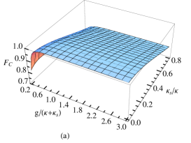
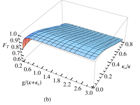
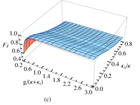
The fidelities and the efficiencies of our universal quantum gates, which vary with the coupling strength and the side leakage rate, are shown in Figs. 5 and 6, respectively. From these figures, one can see that our schemes are feasible in both the strong coupling regime and the weak coupling regime. can be made rather small by improving the sample growth or the etching process.
A QD system has the discrete atom-like energy levels and a spectrum of the ultra-narrow transition that is tunable with the size of the quantum dot. The growth techniques of QDs produce the size variations of the QDs. The spectral line-width inhomogeneous broadening is caused by the fluctuations in the size and shape of a QD, and it has gained the widespread attention inhomg2 . The spectral inhomogeneity is an important property and it is not necessarily a negative consequence for their applications in quantum information processing. The imperfect QD in a realistic system, i.e., the shape of the sample and the strain field distribution are not symmetric, reduces the fidelities of the gates and it can be decreased by designing the shape and the size of the sample or encoding the qubits on a different type of QDs Hu2 ; Hu4 .
The information between the photon medium and the QD spins is transferred by the exciton. That is, the exciton dephasing reduces the fidelities of the gates. The exciton dephasing, including the optical dephasing and the spin dephasing, is sensitive to the dipole coherence time and the cavity-photon coherence time . The exciton dephasing reduces the fidelities of the universal quantum gates less than 10% as it reduces the fidelities by a factor
| (32) |
and the ultralong optical coherence time of the dipole can reach several picoseconds at a low temperature opticldeph1 ; opticldeph2 , while the cavity-photon coherence time is around 10 picoseconds in a InGaAs QD. The QD-hole spin coherence time is long more than 100 nanoseconds Hole-QD .
VI Discussion and summary
Quantum logic gates are essential building blocks in quantum computing and quantum information processing book . CNOT gates are used widely in quantum computing. Directly physical realization of multiqubit gates is a main direction as the optimal length of the unconstructed circuit for a generic -qubit gate is 3CNOT4 .
Some significant progress has been made in realizing universal quantum gates. Refs. Hybrid1 ; Hybrid2 ; NV2 present some interesting schemes for the quantum gates on hybrid light-matter or electron-nuclear qubits. Based on parity-check gates, the CNOT gate on moving electron qubits is proposed in 2004, assisted by an additional electron qubit MoveCNOT . A Toffoli gate on atom qubits with a success probability of 1/2 is constructed by Wei et al. in 2008 Toffoliwei . Our CNOT, Toffoli, and Fredkin gates are compact, simple, and economic as the ancilla qubits, employed in photon5 ; photon9 ; MoveCNOT , are not required, and only a single-photon medium is employed. The proposals for the Toffoli and Fredkin gates beat their synthesis with two-qubit entangling gates and single-qubit gates largely. The optimal synthesis of a three-qubit Toffoli gate requires six CNOT gates Toffolicost and five quantum entangling gates on two individual qubits are required to synthesize a three-qubit Fredkin gate Fredkincost . All our schemes are deterministic and the qubits for the gates are stationary. The side leakage rate of a single-side cavity is usually lower than that of a double-side one Hu3 . Moreover, a QD is easier to be confined in a cavity than an atom hard ; atom4 .
In summary, we have proposed some compact schemes for implementing quantum computing on solid-state electron-spin qubits in the QDs assisted by single-side resonant optical microcavities in a deterministic way. Based on the fact that the -polarized and the -polarized photons reflected by the QD-cavity contribute different phase shifts, the compact quantum circuits for the CNOT, Toffoli, and Fredkin gates on the stationary electron-spin qubits are achieved by some input-output processes of a single-photon medium and some classical feed-forward operations. Our proposals are compact and economic as the additional QD-spin qubits are not required and our schemes for implementing the multiqubit gates beat their synthesis with two-qubit entangling gates and single-qubit gates largely. The success probabilities of our universal quantum gates are 100% in principle. With current technology, our schemes are feasible. Together with single-qubit gates, our universal quantum gates are sufficient for any quantum computing in solid-state QD-spin systems.
Acknowledgments
This work is supported by the National Natural Science Foundation of China under Grant No. 11174039, NECT-11-0031, and the Open Foundation of State key Laboratory of Networking and Switching Technology (Beijing University of Posts and Telecommunications) under Grant No. SKLNST-2013-1-13.
References
- (1) M. A. Nielsen and I. L. Chuang, Quantum Computation and Quantum Information (Cambridge University, Cambridge, 2000).
- (2) A. Barenco, C. H. Bennett, R. Cleve, D. P. DiVincenzo, N. Margolus, P. Shor, T. Sleator, J. A. Smolin, and H. Weinfurter, “Elementary gates for quantum computation,” Phys. Rev. A 52, 3457-3457 (1995).
- (3) Y. Y. Shi, “Both Toffoli and controlled-not need little help to do universal quantum computation,” Quantum Inf. Comput. 3, 084-092 (2003).
- (4) E. Fredkin and T. Toffoli, “Conservative logic,” Int. J. Theor. Phys. 21, 219-253 (1982).
- (5) G. L. Long and L. Xiao, “Parallel quantum computing in a single ensemble quantum computer,” Phys. Rev. A 69, 052303 (2004).
- (6) G. F. Xu, J. Zhang, D. M. Tong, E. Sjöqvist, and L. C. Kwek, “Nonadiabatic holonomic quantum computation in decoherence-free subspaces,” Phys. Rev. Lett. 109, 170501 (2012).
- (7) G. R. Feng, G. F. Xu, and G. L. Long, “Experimental realization of nonadiabatic holonomic quantum computation,” Phys. Rev. Lett. 110, 190501 (2013).
- (8) E. Knill, R. Laflamme, and G. J. Milburn, “A scheme for efficient quantum computation with linear optics,” Nature (London) 409, 46-52 (2001).
- (9) K. Nemoto and W. J. Munro, “Nearly deterministic linear optical controlled-not gate,” Phys. Rev. Lett. 93, 250502 (2004).
- (10) Q. Lin and J. Li, “Quantum control gates with weak cross-Kerr nonlinearity,” Phys. Rev. A 79, 022301 (2009).
- (11) C. W. J. Beenakker, D. P. DiVincenzo, C. Emary, and M. Kindermann, “Charge detection enables free-electron quantum computation,” Phys. Rev. Lett. 93, 020501 (2004).
- (12) C. Y. Hu, A. Young, J. L. O’Brien, W. J. Munro, and J. G. Rarity, “Giant optical Faraday rotation induced by a single-electron spin in a quantum dot: Applications to entangling remote spins via a single photon,” Phys. Rev. B 78, 085307 (2008).
- (13) C. Y. Hu, W. J. Munro, and J. Rarity, “Deterministic photon entangler using a charged quantum dot inside a microcavity,” Phys. Rev. B 78, 125318 (2008).
- (14) C. Bonato, F. Haupt, S. S. R. Oemrawsingh, J. Gudat, D. Ding, M. P. van Exter, and D. Bouwmeester, “CNOT and Bell-state analysis in the weak-coupling cavity QED regime,” Phys. Rev. Lett. 104, 160503 (2010).
- (15) H. R. Wei and F. G. Deng, “Universal quantum gates for hybrid systems assisted by quantum dots inside doublesided optical microcavities,” Phys. Rev. A 87, 022305 (2013).
- (16) H. R. Wei and F. G. Deng, “Scalable photonic quantum computing assisted by quantum-dot spin in double-sided optical microcavity,” Opt. Express 21, 17671-17685 (2013).
- (17) H. F. Wang, A. D. Zhu, S. Zhang, and K. H. Yeon, “Optically controlled phase gate and teleportation of a controlled-NOT gate for spin qubits in a quantum-dot-microcavity coupled system,” Phys. Rev. A 87, 062337 (2013).
- (18) X. Li, Y. Wu, D. Steel, D. Gammon, T. H. Stievater, and D. S. Katzer, “An all-optical quantum gate in a semiconductor quantum dot,” Science 301, 809-811 (2003).
- (19) B. C. Ren, H. R. Wei, and F. G. Deng, “Deterministic photonic spatial-polarization hyper-controlled-not gate assisted by quantum dot inside one-side optical microcavity,” Laser Phys. Lett. 10, 095202 (2013).
- (20) T. Yamamoto, Y. A. Pashkin, O. Astafiev, Y. Nakamura, and J. S. Tsai, “Demonstration of conditional gate operation using superconducting charge qubits,” Nature (London) 425, 941-944 (2003).
- (21) J. Clarke and F. K. Wilhelm, “Superconducting quantum bits,” Nature (London) 453, 1031-1042 (2008).
- (22) W. L. Yang, Z. Q. Yin, Z. Y. Xu, M. Feng, and J. F. Du, “One-step implementation of multiqubit conditional phase gating with nitrogen-vacancy centers coupled to a high-Q silica microsphere cavity,” Appl. Phys. Lett. 96, 241113 (2010).
- (23) F. Jelezko, T. Gaebel, I. Popa, M. Domhan, A. Gruber, and J. Wrachtrup, “Observation of coherent oscillation of a single nuclear spin and realization of a two-qubit conditional quantum gate,” Phys. Rev. Lett. 93, 130501 (2004).
- (24) B. C. Ren and F. G. Deng, “Hyperentanglement purification and concentration assisted by diamond NV centers inside photonic crystal cavities,” Laser Phys. Lett. 10, 115201 (2013).
- (25) J. R. Petta, A. C. Johnson, J. M. Taylor, E. A. Laird, A. Yacoby, M. D. Lukin, C. M. Marcus, M. P. Hanson, and A. C. Gossard, “Coherent manipulation of coupled electron spins in semiconductor quantum dots,” Science 309, 2180-2184 (2005).
- (26) A. Greilich, D. R. Yakovlev, A. Shabaev, A. L. Efros, I. A. Yugova, R. Oulton, V. Stavarache, D. Reuter, A. Wieck, and M. Bayer, “Mode locking of electron spin coherences in singly charged quantum dots,” Science 313, 341-345 (2006).
- (27) D. Press, K. De Greve, P. L. McMahon, T. D. Ladd, B. Friess, C. Schneider, M. Kamp, S. Höfling, A. Forchel, and Y. Yamamoto, “Ultrafast optical spin echo in a single quantum dot,” Nature Photon. 4, 367-370 (2010).
- (28) J. Berezovsky, M. H. Mikkelsen, N. G. Stoltz, L. A. Coldren, and D. D. Awschalom, “Picosecond coherent optical manipulation of a single electron spin in a quantum dot,” Science 320, 349-352 (2008).
- (29) D. Press, T. D. Ladd, B. Y. Zhang, and Y. Yamamoto, “Complete quantum control of a single quantum dot spin using ultrafast optical pulses,” Nature (London) 456, 218-221 (2008).
- (30) J. A. Gupta, R. Knobel, N. Samarth, and D. D. Awschalom, “Ultrafast manipulation of electron spin coherence,” Science 292, 2458-2461 (2001).
- (31) C. Y. Hu and J. G. Rarity, “Loss-resistant state teleportation and entanglement swapping using a quantum-dot spin in an optical microcavity,” Phys. Rev. B 83, 115303 (2011).
- (32) D. F. Walls and G. J. Milburn, Quantum Optics (Springer-Verlag, Berlin, 1994).
- (33) A. B. Young, R. Oulton, C. Y. Hu, A. C. T. Thijssen, C. Schneider, S. Reizenstein, M. Kamp, and S. Höfling, “Quantum-dot-induced phase shift in a pillar microcavity,” Phys. Rev. A 84, 011803 (2011).
- (34) L. M. Duan and H. J. Kimble, “Scalable photonic quantum computation through cavity-assisted interactions,” Phys. Rev. Lett. 92, 127902 (2004).
- (35) C. Bonato, D. Ding, J. Gudat, S. Thon, H. Kim, P. M. Petroff, M. P. van Exter, and D. Bouwmeester, “Tuning micropillar cavity birefringence by laser induced surface defects,” Appl. Phys. Lett. 95, 251104 (2009).
- (36) J. Gudat, C. Bonato, E. van Nieuwenburg, S. Thon, H. Kim, P. M. Petroff, M. P. van Exter, and D. Bouwmeester, “Permanent tuning of quantum dot transitions to degenerate microcavity resonances,” Appl. Phys. Lett. 98, 121111 (2011).
- (37) C. Bonato, E. van Nieuwenburg, J. Gudat, S. Thon, H. Kim, M. P. van Exter, and D. Bouwmeester, “Strain tuning of quantum dot optical transitions via laser-induced surface defects,” Phys. Rev. B 84, 075306 (2011).
- (38) I. J. Luxmoore, E. D. Ahmadi, B. J. Luxmoore, N. A. Wasley, A. I. Tartakovskii, M. Hugues, M. S. Skolnick, and A. M. Fox, “Restoring mode degeneracy in H1 photonic crystal cavities by uniaxial strain tuning,” Appl. Phys. Lett. 100, 121116 (2012).
- (39) J. Hagemeier, C. Bonato, T. A. Truong, H. Kim, G. J. Beirne, M. Bakker, M. P. van Exter, Y. Q. Luo, P. Petroff, and D. Bouwmeester, “H1 photonic crystal cavities for hybrid quantum information protocols,” Opt. Express 20, 24714 (2012).
- (40) R. Albrecht, A. Bommer, C. Deutsch, J. Reichel, and C. Becher, “Coupling of a single nitrogen-vacancy center in diamond to a fiber-based microcavity,” Phys. Rev. Lett. 110, 243602 (2013).
- (41) C. Y. Hu, W. J. Munro, J. L. O’Brien, and J. G. Rarity, “Proposed entanglement beam splitter using a quantum-dot spin in a double-sided optical microcavity,” Phys. Rev. B 80, 205326 (2009).
- (42) A. B. Young, C. Y. Hu, and J. G. Rarity, “Generating entanglement with low-Q-factor microcavities,” Phys. Rev. A 87, 012332 (2013).
- (43) B. C. Ren, H. R. Wei, M. Hua, T. Li, and F. G. Deng, “Complete hyperentangled-bell-state analysis for photon systems assisted by quantum-dot spins in optical microcavities,” Opt. Express 20, 24664-24677 (2012).
- (44) T. J. Wang, S. Y. Song, and G. L. Long, “Quantum repeater based on spatial entanglement of photons and quantum-dot spins in optical microcavities,” Phys. Rev. A 85, 062311 (2012).
- (45) J. P. Reithmaier, G. Sek, A. Löffer, C. Hofmann, S. Kuhn, S. Reitzenstein, L. V. Keldysh, V. D. Kulakovskii, T. L. Reinecke, and A. Forchel, “Strong coupling in a single quantum dot-semiconductor microcavity system,” Nature (London) 432, 197-200 (2004).
- (46) S. Reitzenstein, C. Hofmann, A. Gorbunov, M. Strauß, S. H. Kwon, C. Schneider, A. Löffer, S. Höfing, M. Kamp, and A. Forchel, “AlAs/GaAs micropillar cavities with quality factors exceeding 150.000,” Appl. Phys. Lett. 90, 251109 (2007).
- (47) V. Loo, L. Lanco, A. LemaÎtre, I. Sagnes, O. Krebs, P. Voisin, and P. Senellart, “Quantum dot-cavity strong-coupling regime measured through coherent reflection spectroscopy in a very high-Q micropillar,” Appl. Phys. Lett. 97, 241110 (2010).
- (48) E. Peter, P. Senellart, D. Martrou, A. LemaÎtre, J. Hours, J. M. Gérard, and J. Bloch, “Exciton-photon strong-coupling regime for a single quantum dot embedded in a microcavity,” Phys. Rev. Lett. 95, 067401 (2005).
- (49) C. P. Michael, K. Srinivasan, T. J. Johnson, O. Painter, K. H. Lee, K. Hennessy, H. Kim, and E. Hu, “Wavelength- and material-dependent absorption in GaAs and AlGaAs microcavities,” Appl. Phys. Lett. 90, 051108 (2007).
- (50) T. Yoshie, A. Scherer, J. Hendrickson, G. Khitrova, H. M. Gibbs, G. Rupper, C. Ell, O. B. Shchekin, and D. G. Deppe, “Vacuum Rabi splitting with a single quantum dot in a photonic crystal nanocavity,” Nature (London) 432, 200-203 (2004).
- (51) J. Cui, A. P. Beyler, L. F. Marshall, O. Chen, D. K. Harris, D. D. Wanger, X. Brokmann, and M. G. Bawendi, “Direct probe of spectral inhomogeneity reveals synthetic tunability of single-nanocrystal spectral linewidths,” Nature Chemistry 5, 602 (2013).
- (52) P. Borri, W. Langbein, S. Schneider, U. Woggon, R. L. Sellin, D. Ouyang, and D. Bimberg, “Ultralong dephasing time in InGaAs quantum dots,” Phys. Rev. Lett. 87, 157401 (2001).
- (53) D. Birkedal, K. Leosson, and J. M. Hvam, “Long lived coherence in self-assembled quantum dots,” Phys. Rev. Lett. 87, 227401 (2001).
- (54) D. Brunner, B. D. Gerardot, P. A. Dalgarno, G. Wüst, K. Karrai, N. G. Stoltz, P. M. Petroff, and R. J. Warburton, “A coherent single-hole spin in a semiconductor,” Science 325, 70-72 (2009).
- (55) V. V. Shende, I. L. Markov, and S. S. Bullock, “Minimal universal two-qubit controlled-NOT-based circuits,” Phys. Rev. A 69, 062321 (2004).
- (56) H. Wei, W. L. Yang, Z. B. Deng, and M. Feng, “Many-qubit network employing cavity QED in a decoherence-free subspace,” Phys. Rev. A 78, 014304 (2008).
- (57) V. V. Shende and I. L. Markov, “On the CNOT-cost of Toffoli gate,” Quant. Inf. Comput. 9, 0461-0468 (2009).
- (58) J. A. Smolin and D. P. DiVincenzo, “Five two-bit quantum gates are sufficient to implement the quantum Fredkin gate,” Phys. Rev. A 53, 2855-2856 (1996).
- (59) J. H. An, M. Feng, and C. H. Oh, “Quantum-information processing with a single photon by an input-output process with respect to low-Q cavities,” Phys. Rev. A 79, 032303 (2009).