Security loophole in free-space quantum key distribution due to
spatial-mode detector-efficiency mismatch
Abstract
In free-space quantum key distribution (QKD), the sensitivity of the receiver’s detector channels may depend differently on the spatial mode of incoming photons. Consequently, an attacker can control the spatial mode to break security. We experimentally investigate a standard polarization QKD receiver, and identify sources of efficiency mismatch in its optical scheme. We model a practical intercept-and-resend attack and show that it would break security in most situations. We show experimentally that adding an appropriately chosen spatial filter at the receiver’s entrance may be an effective countermeasure.
I Introduction
Quantum key distribution (QKD) Bennett and Brassard (1984); Ekert (1991), in theory, allows two distant parties Alice and Bob to establish a shared secret key with unconditional security Lo and Chau (1999); Shor and Preskill (2000); Lütkenhaus (2000); Mayers (2001); Renner et al. (2005). Although a number of successful implementations of QKD have been reported Bennett et al. (1992); Gobby et al. (2004); Schmitt-Manderbach et al. (2007); Stucki et al. (2009) and commercialization is underway com , the technology is yet to achieve widespread use. One important reason is that the maximum distance is still of the order of Shibata et al. (2014) in fiber-based systems. Consequently, implementation of free-space QKD utilizing ground-to-satellite links Buttler et al. (1998); Kurtsiefer et al. (2002a, b); Hughes et al. (2002); Weier et al. (2006); Ursin et al. (2007); Erven et al. (2008); Peloso et al. (2009); Nauerth et al. (2013) that promises long-distance quantum communication is now a very attractive field of research.
Implementation imperfections have enabled a number of successful attacks on QKD Sajeed et al. (2015); Jain et al. (2014); Jouguet et al. (2013); Sun et al. (2011); Lydersen et al. (2010); Zhao et al. (2008); Qi et al. (2007); Makarov et al. (2006); Vakhitov et al. (2001); *gisin2006. The main reason behind this is the deviation of the actual behaviour of the devices from the ideal expected behaviour. Thus, to guarantee the security, it is of utmost importance to scrutinize the practical device behaviours for possible deviations. One such source of deviation in free-space QKD can be the assumed symmetry of detection efficiency among all received quantum states in Bob’s detector Makarov et al. (2006); Lamas-Linares and Kurtsiefer (2007); Qi et al. (2007); Zhao et al. (2008); Weier et al. (2011). If a deviation from this assumption exists, an adversary Eve can send light to Bob in different spatial modes so that one of his detectors has a relatively higher probability of click than the other detector(s) Fung et al. (2009). In this way, she can exploit the mismatch in efficiency and make Bob’s measurement outcome dependent on his measurement basis and correlated to Eve, which breaks the assumptions of typical security proofs. In this work, we investigate how crucial this can be to the security of QKD. (While finishing this paper, we became aware of a recent similar work Rau et al. (2015).)
We study a receiver designed for polarization encoding free-space QKD, described in Sec. II. We test it in Sec. III by sending an attenuated laser beam to the receiver with various angle offsets and recording the relative detection probability in each channel, to find incidence angles with high efficiency mismatch. With these data, we show in Sec. IV by numerical modeling that an eavesdropper attack exists that enables Eve to steal the secret key. We discuss countermeasures in Sec. V and conclude in Sec. VI.
II QKD system under test
A free-space QKD receiver typically employs a telescope to reduce the size of a collimated beam, followed by a non-polarizing beamsplitter to randomly choose between two measurement bases. It is followed by polarization beamsplitters and single-photon detectors to measure photons in the four states of polarization: horizontal (H), vertical (V), (D), and (A) Buttler et al. (1998); Kurtsiefer et al. (2002a, b); Hughes et al. (2002); Weier et al. (2006); Ursin et al. (2007); Erven et al. (2008); Peloso et al. (2009); Nauerth et al. (2013). The receiver we test is a prototype for a quantum communication satellite Bourgoin et al. , operating at wavelength [Fig. 1(a,c)]. Its telescope consists of a focusing lens L1 (diameter , focal length ; Thorlabs AC508-250-A) and collimating lens L2 (; Thorlabs A397TM-A). The collimated beam of diameter then passes through a 50:50 beamsplitter BS (custom pentaprism Bourgoin et al. ) and pairs of polarization beamsplitters PBS1 and PBS2 (Thorlabs PBS121). PBS2 increases the polarization extinction ratio in the reflected arm of PBS1. Lenses L3 (Thorlabs PAF-X-18-PC-A) focus the four beams into core diameter multimode fibers (Thorlabs M43L01) leading to single-photon detectors (Excelitas SPCM-AQRH-12-FC).
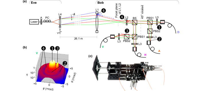
Long-distance free-space QKD receivers are multimode for two reasons. First, propagation of Alice’s beam, initially single-mode, through a turbulent atmosphere splits it into multiple spatial modes Tyson (2010). Second, the finite precision and speed of real-time angular tracking of Alice’s beam requires that Bob accepts multiple spatial modes in a certain acceptance angle Bienfang et al. (2004); Weier et al. (2006); Ursin et al. (2007); Nauerth et al. (2013). Use of single-mode fibers under these conditions would lead to additional coupling losses Takenaka et al. (2012) if the system does not include appropriate (and often expensive) adaptive correction optics Tyson (2010). Therefore, multimode fibers and detectors with larger area are generally preferred as they allow good collection efficiency without increasing complexity and cost.
III Experiment
In order to exploit the mismatch in efficiency, Eve needs to know the mismatch for the four detectors as a function of the input angle. Hence, our first step was to scan Bob’s receiver for possible efficiency mismatch. Eve’s source [Fig. 1(a)] consists of a laser coupled into single-mode fiber, attenuator A, polarization controller PC, and a collimating lens L4 (Thorlabs C220TME-A) mounted on a two-axis motorised translation stage (Thorlabs MAX343/M). In Fig. 1(a), green (light gray) marginal rays denote the initial alignment from Eve, replicating the alignment from Alice to Bob. This is the initial position of the translation stage . As we moved the stage in the transverse plane, it changed the beam’s incidence angle and lateral displacement at Bob’s front lens L1 simultaneously. This is shown by red (dark gray) marginal rays in Fig. 1(a), representing a beam from Eve coming at an angle relative to the initial beam.
Before scanning, the optics in Bob’s apparatus was aligned to maximize coupling into all four detectors at the normal incidence, which is the standard alignment procedure for QKD. Note that many free-space QKD systems employ a real-time tracking system to maintain this initial alignment Bienfang et al. (2004); Weier et al. (2006); Ursin et al. (2007); Nauerth et al. (2013). We then started the scanning procedure that involved first, changing the outgoing beam’s angle , and then recording the corresponding count rate at all four detectors of Bob. For each data point, we used an integration time of . Our scan consisted of approximately data points in a square matrix covering the whole clear aperture of Bob’s front lens L1. Then during post-processing, for each data point for each detector, we subtracted the corresponding detector’s background count rate, and then normalized it by dividing by the maximum count rate in that detector.
At first, we did a preliminary scan using optical power meters (Thorlabs PM200 with S130C head) that revealed several features, highlighted in Fig. 1(b). Around , maximum light coupling resulted in the central peak ❶. With increasing scanning angle, the focused beam started missing the fiber core, and the detector count dropped off ❷. A region was found when the beam reflected off a polished edge of PBS2 back into the fiber core, causing the peak ❸. Increasing the angle further made the beam hit the anodized aluminum mount of L1 and possibly edges of other lens mounts and round elements in the optical assembly. It was scattered at these edges, producing two ring-like features ❹. Beyond these features, there were no noticeable power reading, as the beam completely missed the receiver aperture.
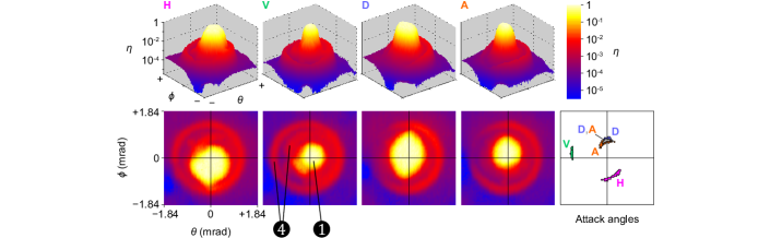
We then adjusted the receiver setup to minimize the peak ❸, and performed final scans at distance using Bob’s single-photon detectors (Excelitas SPCM-AQRH-12-FC). During these scans, the beam at L1 was Gaussian-shaped with width (at peak intensity). The scans were done in steps covering range, corresponding to lateral displacement of at L1. Figure 2 shows the normalized detection efficiency in all four receiver channels as a function of . Most of the original features are still visible. However, outside the narrow central range of angles close to , individual channel’s efficiencies vary independently. Also, the size and shape of the central peak is significantly different between channels. This was impossible to identify during the normal alignment procedure. This effect can be attributed to imprecise focusing, optical path length difference between the arms, off-centered alignment of lenses, mode-dependent bending loss in fibers, and individual variations in components. These may have also caused the efficiency at one side of the outer ring being higher. Because of these reasons, there exist angles such that if photons are sent at those angles, one channel has a much higher click probability than the rest.
IV Attack model
To emphasize the security threat, it is useful to model an attack that exploits the discovered side-channel. One possible attack is the faked-state attack Makarov et al. (2006); Makarov and Hjelme (2005), which is an intercept-and-resend attack in which Eve attempts to deterministically control Bob’s basis choice and detection outcome. We model a practical faked-state attack using the obtained data and the following assumptions: Alice and Bob perform non-decoy-state Bennett-Brassard 1984 (BB84) protocol using polarization encoding. Alice emits weak coherent pulses with mean photon number equal to Alice–Bob line transmittance Lütkenhaus (2000). Whenever Bob registers a multiple click, he performs a squashing operation (double-click in one basis is mapped to a random value in that basis, while multiple clicks in different bases are discarded) Beaudry et al. (2008); Tsurumaru and Tamaki (2008); Gittsovich et al. (2014). Alice and Bob also monitor total sifted key rate, and quantum bit error ratio (QBER). Eve has information about Bob’s receiver characteristics described above, and only uses devices available in today’s technology. She intercepts photons at the output of Alice, using an active basis choice and superconducting nanowire detectors, with overall detection efficiency and dark count probability per bit slot Marsili et al. (2013). Then, a part of her, situated close to Bob, regenerates the measured signal and sends to Bob. We assume that Alice–Bob and Alice–Eve fidelity Bourgoin et al. , while Eve–Bob experimentally measured . Here fidelity refers to the probability that a polarized photon will emerge from the PBS at the correct path, which is related to visibility by . We also confirmed experimentally that Eve–Bob fidelity is preserved at all illumination angles shown in Fig. 2.
From Eve’s point of view, she wants to maximize the detection probability when Bob measures in compatible (i.e., same as her) basis, to maximize Eve–Bob mutual information. Also, she wants to minimize Bob’s detection probability in non-compatible basis, to minimize QBER. Let be the efficiency of Bob’s -th channel () given that incoming light is polarized. Thus to find attack points for the -th polarization, we choose angles that have higher values of and , where and are the normalized efficiencies of the two detectors in the non-compatible basis. Our experimental attack angles are shown in the rightmost plot in Fig. 2. For example, the H attack angles were composed of points for which and . Similarly, for the V, D and A attack angles, , ; , ; , . The thresholds used here to find the attack angles were not optimal, and were picked manually.
To derive the key rate and QBER formula in Eve’s presence, we start with a system with only Eve and Bob. Let’s consider Eve sending an -polarized pulse to Bob within the attack angles H. Before squashing, the raw click probability that detector in Bob clicks given Eve has sent -polarized light is
| (1) | ||||
where is Eve’s mean photon number and is Bob’s background click probability per bit slot in -th channel. The probability that after squashing Bob measures in HV basis, given Eve has sent an -polarized pulse, is composed of three events: when only detector H clicks, when only detector V clicks, or when both click. It can be written as
| (2) | ||||
Let’s now include Alice into the picture. Consider Alice sends an -polarized pulse, and Eve intercepts it. Let and be the probability that Eve measures in the compatible basis (i.e., the same basis as Alice) and gets a click only in the correct and wrong detector respectively. Let be the probability that she measures in the non-compatible basis (different basis than Alice’s) and gets a click in a single detector. The sifted key rate given Alice has sent -polarized light is
| (3) | ||||
An error can occur when Eve measures Alice’s signal in non-compatible basis or when Eve measures in compatible basis but Bob measures a wrong value owing to imperfect fidelity or dark count. Hence, the error rate conditioned on Alice sending -polarized light is
| (4) | ||||
where is the probability that Bob measures value after squashing, given Eve has sent -polarized light. For example,
| (5) |
Sifted key rates and errors in Eve’s presence [Eqs. 3 and 4] conditioned on , , polarizations sent by Alice can be calculated similarly. The total sifted key rate and QBER in Eve’s presence become
| (6) | ||||
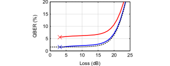
The only free parameters left for Eve to manipulate are the mean photon numbers of her signal. Knowing the angular scanning data, Eve can use a numerical optimization to find values of , , , that minimize while keeping , where is Bob’s sifted key rate without Eve. Our numerical optimization achieves this for Alice–Bob channel loss if they are willing to accept a slight increase of QBER by less than (see Fig. 3). Here we assumed Bob’s detector parameters as measured by us: efficiency at was in all four channels, and individual detector background count probabilities were in the range of to per coincidence window. These optimization results are realistic conditions for a successful attack on most communication channels Buttler et al. (1998); Kurtsiefer et al. (2002a, b); Hughes et al. (2002); Ursin et al. (2007); Erven et al. (2008); Nauerth et al. (2013); Bourgoin et al. Note that the distance Eve–Bob can be increased without affecting attack performance, by replacing Eve’s illuminator with four collimators oriented at the required attack angles.
We went further and imposed an additional constraint on Eve to make . Our optimization shows that it is still possible for Eve to pick appropriate mean photon numbers and successfully attack the system with resultant QBER in – line loss range (Fig. 3). Similar QBER values are typical for outdoor channels, because of background light. Eve could shield Bob from the latter to hide QBER resulting from her attack.
We would like to point out that the attack angles depend on the way the setup is constructed, the imperfections of each individual sample of component, and each individual alignment procedure. I.e., no two setups are identical, even if they are produced in the same assembly line, and they will generally have different attack angles. However, from a theoretical point of view, in quantum cryptography it is assumed from Kerckhoffs’ principle Kerckhoffs (1883) that except for the keys themselves, Eve has knowledge about all other parameters in the system. It is thus a valid assumption that she knows the attack angles. From a practical point of view, Eve may try techniques proposed in Makarov and Hjelme (2005). She may replace a small fraction of the signal states with faked states at different spatial angles, then listen to the classical communication to get an estimate of the efficiency of Bob’s detectors at those angles. In this way she may gradually improve her estimate on the mismatch without causing excessive QBER. When she has enough information on the statistics of the mismatch, she can launch her full-fledged attack.
V Countermeasures
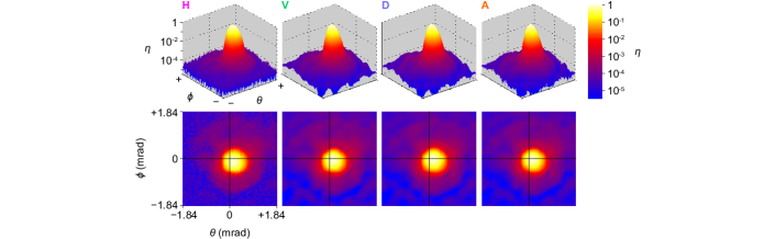
In our attack, by sending lights at different angles, Eve has broken a fundamental assumption of security proofs that detection probabilities are independent of detection basis Tomamichel et al. (2012); Inamori et al. (2007). We propose to restore this assumption by placing a spatial filter (pinhole) at the focal plane of Bob’s L1 and L2 [Fig. 1(a)]. Spatial filtering is sometimes done before the beamsplitters to increase signal-to-background ratio in the channel Hughes et al. (2002); Weier et al. (2006); Peloso et al. (2009), however it has not been characterised as a security countermeasure. We performed scanning with , , and diameter pinholes, and found that decreasing the pinhole diameter gradually reduces the mismatch. The diameter pinhole eliminated any visible mismatch (Fig. 4) even though we reduced our search parameters to and . This pinhole provides Bob’s field-of-view of , which does not reduce his efficiency with turbulent atmospheric channels Ursin et al. (2007). Hence, we conclude that a pinhole may be an efficient countermeasure for the current setup.
Note that, in Refs. Qi et al., 2007 and da Silva et al., 2015, a detector scrambling strategy was proposed that might be an effective countermeasure against efficiency mismatch attacks for single-photon qubits. However, it is not clear how effective that countermeasure is, when one considers that the detectors operate on optical modes, not on single-photon signals. This can be a future study.
VI Conclusion
Our analysis implies that data obtained during a QKD session can be explained by an intercept-resend attack exploiting the spatial mode side-channels. Therefore, there is no postprocessing or privacy amplification that can eliminate Eve’s knowledge without sacrificing all key Curty et al. (2004). Although our practical attack should work, and the physical countermeasure seems promising, there is still room for improvement on both the attack scheme and countermeasures. Eve can employ more attack angles or combine this attack with some other suitable attack schemes, to increase the number of her free parameters. Alice and Bob can make this harder by monitoring more parameters. We expect that our attack can be conducted also in the related decoy-state protocol Hwang (2003), though the requirement to match the correct decoy statistics will modify the parameter regime where it will be effective. Another possible future study is to fully implement the present attack under realistic outdoor channel conditions.
Acknowledgements.
We thank Y. Zhang and M. Mosca for discussions. This work was supported by US Office of Naval Research, Industry Canada, CFI, Ontario MRI, NSERC, Canadian Space Agency, and CryptoWorks21. P.C. acknowledges support by Thai DPST scholarship. J.-P.B. and T.J. acknowledge support from FED DEV.References
- Bennett and Brassard (1984) C. H. Bennett and G. Brassard, in Proceedings of IEEE International Conference on Computers, Systems, and Signal Processing (IEEE Press, New York, Bangalore, India, 1984) pp. 175–179.
- Ekert (1991) A. K. Ekert, Phys. Rev. Lett. 67, 661 (1991).
- Lo and Chau (1999) H.-K. Lo and H. F. Chau, Science 283, 2050 (1999).
- Shor and Preskill (2000) P. W. Shor and J. Preskill, Phys. Rev. Lett. 85, 441 (2000).
- Lütkenhaus (2000) N. Lütkenhaus, Phys. Rev. A 61, 052304 (2000).
- Mayers (2001) D. Mayers, J. ACM 48, 351 (2001).
- Renner et al. (2005) R. Renner, N. Gisin, and B. Kraus, Phys. Rev. A 72, 012332 (2005).
- Bennett et al. (1992) C. H. Bennett, F. Bessette, L. Salvail, G. Brassard, and J. Smolin, J. Cryptology 5, 3 (1992).
- Gobby et al. (2004) C. Gobby, Z. L. Yuan, and A. J. Shields, Appl. Phys. Lett. 84, 3762 (2004).
- Schmitt-Manderbach et al. (2007) T. Schmitt-Manderbach, H. Weier, M. Fürst, R. Ursin, F. Tiefenbacher, T. Scheidl, J. Perdigues, Z. Sodnik, C. Kurtsiefer, J. G. Rarity, A. Zeilinger, and H. Weinfurter, Phys. Rev. Lett. 98, 010504 (2007).
- Stucki et al. (2009) D. Stucki, N. Walenta, F. Vannel, R. T. Thew, N. Gisin, H. Zbinden, S. Gray, C. R. Towery, and S. Ten, New J. Phys. 11, 075003 (2009).
- (12) Commercial QKD systems are available for purchase, as of 2015, from at least three entities: ID Quantique (Switzerland), http://www.idquantique.com; SeQureNet (France), http://www.sequrenet.com; and Austrian Institute of Technology (Austria), http://www.ait.ac.at/.
- Shibata et al. (2014) H. Shibata, T. Honjo, and K. Shimizu, Opt. Lett. 39, 5078 (2014).
- Buttler et al. (1998) W. T. Buttler, R. J. Hughes, P. G. Kwiat, S. K. Lamoreaux, G. G. Luther, G. L. Morgan, J. E. Nordholt, C. G. Peterson, and C. M. Simmons, Phys. Rev. Lett. 81, 3283 (1998).
- Kurtsiefer et al. (2002a) C. Kurtsiefer, P. Zarda, M. Halder, H. Weinfurter, P. M. Gorman, P. R. Tapster, and J. G. Rarity, Nature 419, 450 (2002a).
- Kurtsiefer et al. (2002b) C. Kurtsiefer, P. Zarda, M. Halder, P. M. Gorman, P. R. Tapster, J. G. Rarity, and H. Weinfurter, Proc. SPIE 4917, 25 (2002b).
- Hughes et al. (2002) R. J. Hughes, J. E. Nordholt, D. Derkacs, and C. G. Peterson, New J. Phys. 4, 43 (2002).
- Weier et al. (2006) H. Weier, T. Schmitt-Manderbach, N. Regner, C. Kurtsiefer, and H. Weinfurter, Fortschr. Phys. 54, 840 (2006).
- Ursin et al. (2007) R. Ursin, F. Tiefenbacher, T. Schmitt-Manderbach, H. Weier, T. Scheidl, M. Lindenthal, B. Blauensteiner, T. Jennewein, J. Perdigues, P. Trojek, B. Ömer, M. Fürst, M. Meyenburg, J. Rarity, Z. Sodnik, C. Barbieri, H. Weinfurter, and A. Zeilinger, Nat. Phys. 3, 481 (2007).
- Erven et al. (2008) C. Erven, C. Couteau, R. Laflamme, and G.Weihs, Opt. Express 16, 16840 (2008).
- Peloso et al. (2009) M. P. Peloso, I. Gerhardt, C. Ho, A. Lamas-Linares, and C. Kurtsiefer, New J. Phys. 11, 045007 (2009).
- Nauerth et al. (2013) S. Nauerth, F. Moll, M. Rau, C. Fuchs, J. Horwath, S. Frick, and H. Weinfurter, Nat. Photonics 7, 382 (2013).
- Sajeed et al. (2015) S. Sajeed, I. Radchenko, S. Kaiser, J.-P. Bourgoin, A. Pappa, L. Monat, M. Legré, and V. Makarov, Phys. Rev. A 91, 032326 (2015).
- Jain et al. (2014) N. Jain, E. Anisimova, I. Khan, V. Makarov, C. Marquardt, and G. Leuchs, New J. Phys. 16, 123030 (2014).
- Jouguet et al. (2013) P. Jouguet, S. Kunz-Jacques, and E. Diamanti, Phys. Rev. A 87, 062313 (2013).
- Sun et al. (2011) S.-H. Sun, M.-S. Jiang, and L.-M. Liang, Phys. Rev. A 83, 062331 (2011).
- Lydersen et al. (2010) L. Lydersen, C. Wiechers, C. Wittmann, D. Elser, J. Skaar, and V. Makarov, Nat. Photonics 4, 686 (2010).
- Zhao et al. (2008) Y. Zhao, C.-H. F. Fung, B. Qi, C. Chen, and H.-K. Lo, Phys. Rev. A 78, 042333 (2008).
- Qi et al. (2007) B. Qi, C.-H. F. Fung, H.-K. Lo, and X. Ma, Quant. Inf. Comp. 7, 73 (2007).
- Makarov et al. (2006) V. Makarov, A. Anisimov, and J. Skaar, Phys. Rev. A 74, 022313 (2006), erratum ibid. 78, 019905 (2008).
- Vakhitov et al. (2001) A. Vakhitov, V. Makarov, and D. R. Hjelme, J. Mod. Opt. 48, 2023 (2001).
- Gisin et al. (2006) N. Gisin, S. Fasel, B. Kraus, H. Zbinden, and G. Ribordy, Phys. Rev. A 73, 022320 (2006).
- Lamas-Linares and Kurtsiefer (2007) A. Lamas-Linares and C. Kurtsiefer, Opt. Express 15, 9388 (2007).
- Weier et al. (2011) H. Weier, H. Krauss, M. Rau, M. Fürst, S. Nauerth, and H. Weinfurter, New J. Phys. 13, 073024 (2011).
- Fung et al. (2009) C.-H. F. Fung, K. Tamaki, B. Qi, H.-K. Lo, and X. Ma, Quant. Inf. Comp. 9, 131 (2009).
- Rau et al. (2015) M. Rau, T. Vogl, G. Corrielli, G. Vest, L. Fuchs, S. Nauerth, and H. Weinfurter, IEEE J. Quantum Electron. 21, 6600905 (2015).
- (37) J.-P. Bourgoin, N. Gigov, B. L. Higgins, Z. Yan, E. Meyer-Scott, A. Khandani, N. Lütkenhaus, and T. Jennewein, (manuscript in preparation).
- Tyson (2010) R. Tyson, Principles of Adaptive Optics, 3rd ed. (CRC Press, 2010).
- Bienfang et al. (2004) J. C. Bienfang, A. J. Gross, A. Mink, B. J. Hershman, A. Nakassis, X. Tang, R. Lu, D. H. Su, C. W. Clark, and C. J. Williams, Opt. Express 12, 2011 (2004).
- Takenaka et al. (2012) H. Takenaka, M. Toyoshima, and Y. Takayama, Opt. Express 20, 15301 (2012).
- Makarov and Hjelme (2005) V. Makarov and D. R. Hjelme, J. Mod. Opt. 52, 691 (2005).
- Beaudry et al. (2008) N. J. Beaudry, T. Moroder, and N. Lütkenhaus, Phys. Rev. Lett. 101, 093601 (2008).
- Tsurumaru and Tamaki (2008) T. Tsurumaru and K. Tamaki, Phys. Rev. A 78, 032302 (2008).
- Gittsovich et al. (2014) O. Gittsovich, N. J. Beaudry, V. Narasimhachar, R. R. Alvarez, T. Moroder, and N. Lütkenhaus, Phys. Rev. A 89, 012325 (2014).
- Marsili et al. (2013) F. Marsili, V. B. Verma, J. A. Stern, S. Harrington, A. E. Lita, T. Gerrits, I. Vayshenker, B. Baek, M. D. Shaw, R. P. Mirin, and S. W. Nam, Nat. Photonics 7, 210 (2013).
- Kerckhoffs (1883) A. Kerckhoffs, J. des Sciences Militaires IX, 5 (1883).
- Tomamichel et al. (2012) M. Tomamichel, C. C. W. Lim, N. Gisin, and R. Renner, Nat. Commun. 3, 634 (2012).
- Inamori et al. (2007) H. Inamori, N. Lütkenhaus, and D. Mayers, Eur. Phys. J. D 41, 599 (2007).
- da Silva et al. (2015) T. F. da Silva, G. C. do Amaral, G. B. Xavier, G. P. Temporão, and J. P. von der Weid, IEEE J. Sel. Top. Quantum Electron. 21, 1 (2015).
- Curty et al. (2004) M. Curty, M. Lewenstein, and N. Lütkenhaus, Phys. Rev. Lett. 92, 217903 (2004).
- Hwang (2003) W.-Y. Hwang, Phys. Rev. Lett. 91, 057901 (2003).