Dark-field hyperlens: Super-resolution imaging of weakly scattering objects
Abstract
We propose and numerically demonstrate a technique for subwavelength optical imaging based on a metal-dielectric multilayer hyperlens designed in such a way that only the large-wavevector waves are transmitted while all propagating waves from the image area are blocked by the hyperlens. As a result, the image plane only contains scattered light from subwavelength features of the objects and is free from background illumination. Similar in spirit to conventional dark-field microscopy, the proposed dark-field hyperlens is numerically shown to enhance the subwavelength image contrast by more than two orders of magnitude. These findings are promising for optical imaging of weakly scattering subwavelength objects, such as optical nanoscopy of label-free biological objects.
keywords:
hyperbolic metamaterials, hyperlens, superresolution, dark-field microscopyDTU Fotonik, Technical University of Denmark, Ørsteds pl. 343, 2800 Kongens Lyngby, Denmark \abbreviationsIR,NMR,UV
We propose and numerically demonstrate a technique for subwavelength imaging based on a metal-dielectric multilayer hyperlens designed in such a way that only the large-wavevector waves are transmitted while all propagating waves from the image area are blocked by the hyperlens. As a result, the image plane only contains scattered light from subwavelength features of the objects and is free from background illumination. Similar in spirit to conventional dark-field microscopy, the proposed dark-field hyperlens is promising for optical imaging of weakly scattering subwavelength objects, such as optical nanoscopy of label-free biological objects.
1 Introduction
The recent decade in modern materials science has featured the advent of optical metamaterials, where the role of known, ordinary constituents of matter (atoms, ions, or molecules) is bestowed upon artificial “meta-atoms”—nanosized objects purposely designed to have the desired optical properties 1. If the meta-atoms are much smaller than the wavelength of light interacting with them, then the meta-atom assembly, or an artificial composite metamaterial, would exhibit the desired properties macroscopically. The elegance of the metamaterials concept lies in the nearly limitless potential variety of meta-atom shapes and compositions, which surpasses the variety of naturally occurring atoms, molecules and crystals (and, in turn, of natural materials).
The hallmark success of optical metamaterials is the design of artificial materials with optical properties that do not exist in naturally occurring media, such as negative refractive index 2. Such negative-index media came out as seminal to the metamaterials field because of the vision of the “perfect lens” 3, where a slab of an artificial material with (a “super-lens”) would focus light tighter than diffraction would allow in a conventional optical system. Even though this “perfect lens” dream, which hinges on the existence of lossless and isotropic negative-index metamaterials, may never come true, it did give birth to the entire field of study with several successful experimental demonstrations of subwavelength imaging 4, 5, 6, 7. It was understood that the operating principle of the superlens is its ability to transmit, rather than to lose, the near-field information about a subwavelength object 8, as seen in 1(a–c).
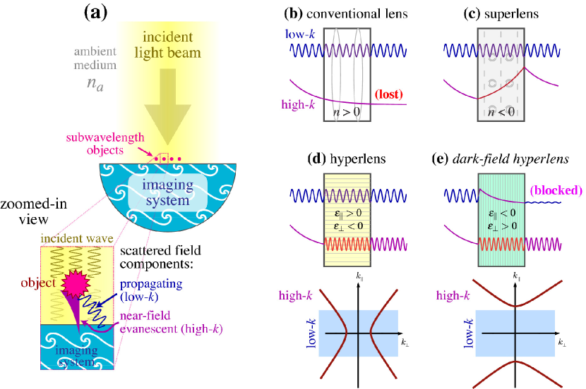
Later studies have shown that so-called hyperbolic metamaterials (HMMs)10, which are extremely anisotropic media that are metal-like along some coordinate axes and dielectric-like along others, make it possible to do more—to convert the near field of an object into a set of propagating waves to be later imaged by conventional means. This concept of the hyperlens 9 1(d), followed by experimental demonstrations12, showed that subwavelength imaging could be far closer to reality than one would assume after the initial disappointment in the superlens. Subsequent theoretical studies have further shown that a broad variety of structures, including metal-dielectric multilayers11, possess the necessary requirements to function in a hyperlens. Such multilayers are of much simpler geometry than metamaterials commonly required to achieve negative refractive index.
The existing designs of the hyperlens recover information from both propagating (low-) waves with and evanescent (high-) waves with (where is the ambient refractive index and ). Such an approach is undoubtedly the best way of maximizing the output from the object to create the brightest possible subwavelength image. However, this approach has a serious downside: any propagating waves that exist in the object area but do not originate form the object (such as incident or stray light) would be transmitted, creating strong background in the image area. It is for this reason that existing demonstrations of the hyperlens focus on examples where background radiation can be eliminated. This is done either by imaging a subwavelength pattern in a metal screen 12, 13, 14 that covers the entire lens and blocks all incident light, or else by using self-illuminating objects such as fluorescent centers 15, 16. In a scenario when objects to be imaged are weakly scattering and have to be illuminated by external light, as is very relevant in label-free biological imaging, a conventional hyperlens would be nearly useless because the resulting image would have extremely low contrast.
In this paper, we propose an alternative hyperlensing concept which is free from this downside and can provide high-contrast subwavelength images of weakly scattering objects. The proposed device only transmits high- waves while blocking all propagating radiation in the sample area (1d), be it from the object itself or from elsewhere. The resulting image would therefore only contain information coming from subwavelength features of the sample, providing a much greater contrast than the conventional hyperlens. The proposed device relates to the conventional hyperlens in the same way as dark-field microscopy relates to conventional optical microscopy. Therefore we have termed the proposed device the dark-field hyperlens (DFHL), and the proposed concept, dark-field superresolving optical microscopy. Unlike an earlier work of 2012 by H. Benisty, where the term dark-field hyperlens was first coined17, the filtering of the background radiation is done by the imaging hyperlens itself rather than by using a second hyperlens to excite the sample in the confocal geometry. As a result, the proposed device geometry is much simpler and within easier reach of modern fabrication facilities.
It should be stressed that beating the diffraction limit in the optical microscopy would constitute a major breakthrough in biological imaging because it neither requires special sample fixation and preparation techniques (such as electron-microscopy and scanning-microscopy methods) nor relies on special labeling methods (such as STED-like approaches18). As a result, the proposed dark-field superresolving optical microscopy can be used to obtain dynamic real-time images of weak-contrast subwavelength objects. Being able to see and investigate dynamic processes involving very small biological agents and macromolecules would be truly enabling to modern life sciences, as confirmed by the ongoing scientific efforts in search for such a technique19, 20, 21. Hence, the impact of such subwavelength optical microscopy, or nanoscopy, that would be high-resolution, high-contrast, fast, and non-destructive to the specimen—such as the dark-field hyperlens can potentially provide—can potentially be on par with the impact of the original invention of an optical microscope on biology several centuries ago. The accompanying possibility to reverse the operation of a hyperlens in order to selectively excite an object on a subwavelength scale may bring about an even greater advance in experimental biology, making it possible not only to observe the functioning of nanoscale biological agents, but also to actively interfere with them.
The paper is organized as follows. Section 2 introduces the principle of the DFHL, providing analytical guidelines to its operation. Section 3 deals with the numerical demonstration using planar-geometry HMM as a toy-model or “poor man’s” hyperlens, which provides subwavelength imaging without magnification. Section 4 moves on to provide a numerical demonstration of a cylindrical-geometry DFHL, confirming subwavelength imaging functionality with magnification rate of 2.5 for objects down to 300 nm apart. Finally, Section 5 summarizes the paper.
2 Operating principle of the dark-field hyperlens
The primary physical concept behind subwavelength imaging in plasmonic metamaterials—the operating principle of the hyperlens—is the idea that a medium with extreme anisotropy, such that the components of the permittivity tensor have different signs, supports propagating waves with very large wave vectors. Indeed, recalling the dispersion relation for the extraordinary (TM-polarized) wave in a uniaxial birefringent medium, we get
| (1) |
where and are components of the dielectric permittivity tensor ; and are respective components of the wave vector. We see that for normal isotropic or weakly birefringent media the solutions of (1) in the -space represent bounded shapes (ellipsoids), providing an upper limit on the possible values of for propagating waves. In contrast, if the optical anisotropy is so strong that and are of different signs, then the solutions of (1) change topology from bounded ellipsoids to unbounded hyperboloids, thus supporting propagating solutions with theoretically infinite wave vectors22.
This fact had remained largely a theoretical curiosity until such hyperbolic dispersion could actually be realized for optical waves in HMMs—subwavelength metal-dielectric structures with rather simple geometries such as nanorod arrays and multilayers 10, 11. It was shown that even though “infinitely large wave vectors” proved to be an idealization23, HMMs can indeed support propagating plasmonic waves with very large -vectors24.
As a result, an HMM can transform high- waves with , which are evanescent in the ambient medium with refractive index , to high- waves that can propagate through the metamaterial. To see how this gives rise to subwavelength imaging properties, we recall that any object’s scattered field can be decomposed into a series of plane waves spanning the entire range of . The relation between the spatial representation of the object and its image in the Fourier optics approach is
| (2) |
Here is the transfer function of the imaging system, and it can be seen from the properties of Fourier transformation that (the image is perfect) if . In conventional optics, propagation of light over some distance in the ambient medium introduces a low-pass filter in the -space, resulting in the transfer function with . Therefore, if the object’s Fourier image is significantly extended into the area with , or in other words, if the size of the object is smaller than the wavelength of light , then all the components with (the near-field information) are lost (see 1(b)), and the image becomes blurred.
This low-pass filtering is overcome in HMMs, where (1) results in the expression
| (3) |
which can remain real for very large because . This makes the transfer function such that the loss of near-field information is prevented (see 1(d)). Thus, placing an HMM close to the object facilitates superresolution imaging.
This idea, combined with the use of curvilinear geometry so that high- waves inside the metamaterial can be further coupled to outside propagating waves and imaged by a conventional lens, was put to use in the practical realization of the hyperlens12. Later studies followed with experimental demonstration of a spherical hyperlens at visible frequencies 13 and the design of an all-dielectric hyperlens25, as well as with applications to other platforms such as terahertz 16 and acoustic 15 waves.
Depending on the signs of the eigenvalues in the dielectric permittivity tensor, hyperbolic media can be classified as either type I () or type II ()26. In the periodic metal-dielectric multilayer geometry, the effective permittivity components can be obtained from the Maxwell-Garnett homogenization approach with 23
| (4) |
where is the filling fraction of the metal. Therefore, by choosing the thicknesses of metal and dielectric layers in the stack ( and ), as well as the permittivities of metal and dielectric ( and ), one can design a structure that is effectively a type-I or type-II HMM.
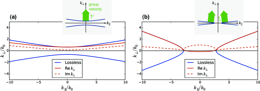
The key difference between the two types of HMMs can be seen from (1): the dispersion contour in the wave vector space has a different topology, forming either one connected or two unconnected hyperboloidal surfaces (see 2 for example structures). As a result [see (3)], type-I HMMs support bulk propagating waves with any value of the tangential wave vector , and act like dielectrics for TE-polarized (ordinary) waves. In contrast, type-II HMMs only support TM-polarized bulk propagating waves for , exhibiting effective metallic properties for lower as well as for the TE-polarized waves.
Consider now a scenario where there is a subwavelength object placed in front of an HMM-based hyperlens and illuminated by external light. At first sight, a type-I HMM is much better suited for the design of the hyperlens because it transmits both propagating components of the scattered radiation (with ) and all the evanescent components (with , where is the refractive index of the ambient medium). As a result, subwavelength image with maximum resolution and good brightness can be formed. However, a type-I HMM would transmit the propagating low- components originating not only from the object, but also from other sources, such as incident or stray light. Therefore, if the object to be imaged is weakly scattering (as is the case with most subwavelength objects made of dielectrics, such as all biological objects), the resulting image would have very low contrast, rendering such a hyperlens extremely difficult in use.
What we propose as the main idea of this paper is to modify the hyperlens in such a way that a type-I HMM is replaced with a type-II one designed so that exceeds . This would filter all low- propagating components, so that only the high- waves stemming from the objects to be imaged would make it to the image area. Such a device would in some sense represent the “inverse” of the conventional optics [compare 1(b) and (e)], introducing high-pass rather than low-pass filtering in the transfer function of the hyperlens.
To see that such high-pass filtering still allows a subwavelength image to be formed, we rewrite (2), reducing it to one dimension (assuming ) for simplicity:
| (5) |
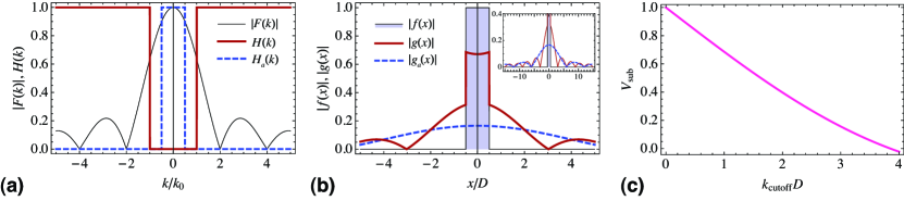
where the object of size is represented by the rectangular (unit box) function that assumes unity value for and zero value elsewhere. In this formalism, the high-pass filtering action of the type-II HMM blocking all the waves below can be modelled by assuming the transfer function (see 3(a)), which results in the image of the form
| (6) |
where is the sine integral function. We see that the high-pass filtering retains the presence of the image in the form of the first term in (6), the second term adding some minor background to the image as seen in 3(b). This is unlike the action of the low-pass filtering induced by propagation in some isotropic ambient medium, which can be modelled by similarly assuming the box-type transfer function and results in
| (7) |
which becomes increasingly blurred as the decreases to values significantly below unity.
Therefore, we conclude that the image formed by a hyperlens based on the type-II rather than type-I HMM would still be subwavelength as per (6), but would have a greatly enhanced contrast compared to the conventional hyperlens because the object-unrelated background, such as signal stemming from the incident light, is blocked. Specifically, the subwavelength image contract, which can be defined as the visibility
| (8) |
can be seen in 3(c) to be significant for below 2, and to approach unity as the object size decreases.
We can see that the proposed hyperlens modification is similar in spirit to dark-field microscopy, where background illumination is blocked and only the information coming from the specimen is isolated. Therefore, we call the proposed hyperlens the dark-field hyperlens (DFHL), and will by contrast refer to the conventional hyperlens as the bright-field hyperlens (BFHL).
3 Planar-geometry “poor man’s” dark-field hyperlens
To demonstrate the proposed concept and to compare the functionality of DFHL and BFHL and, we have numerically simulated light propagation in a scenario where two subwavelength metallic scatterers are placed in front of planar hyperlens structures; the scatterers are separated by a distance shorter than the wavelength of the plane wave incident on them. The planar hyperlens geometry is chosen for simplicity, and we call such a structure “the poor man’s DFHL” because such a design is only able to transmit a subwavelength image of an object some distance without true magnification, by the same token as a slab of metal is dubbed “the poor man’s superlens”27. However, despite the obvious drawbacks of this “toy model”, it is useful as a proof-of-principle that can demonstrate the operating principle of the proposed DFHL without having to regard features brought about by more complicated designs.
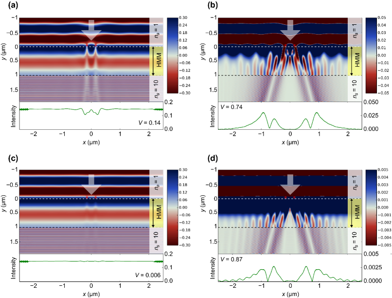
The results of the simulation are shown in 4. The structures are multilayers made of alternating metal and dielectric layers, with layers in total. All layers have 10 nm thickness, and the BFHL and DFHL structures differ by the material parameters of the metal and dielectric used, with 2 showing the corresponding dispersion properties in the effective medium limit (i.e., assuming infinitely thin layers) with and without losses.
COMSOL finite element software was used for the simulations. We adopt the supercell approach when the simulation domain is periodic in the direction (tangential to the layers, see 4) in order to avoid numerical errors arising from metal layers terminating inside perfectly-matched layers (PML) region. (These errors can be significant because the performance of absorbing boundary conditions such as PMLs for the high- waves existing in HMMs is unstudied and can be very poor.) To prevent artifacts arising from interaction between the scatterers from different supercells, we make the width of the simulation domain 5 µm, so any periodicity effects are expected to be negligible. In the direction (normal to the layers), absorbing boundary conditions are used, with 200 nm thick PMLs placed 1 µm away from the multilayer. A normally incident plane wave with wavelength 715 nm is impinging on the hyperlens from the ambient medium with refractive index , excited in the simulaiton by surface current boundary condition. On the other side of the multilayer, a substrate with artificially high refractive index () is placed so that high- waves remain propagating, and the subwavelength image pattern can be visualized.
As expected, 4(a) shows that the BFHL transmits a significant portion of the incident plane wave with , which creates a strong background in the image area. The images of the objects are manifest as faint “shadows” where the intensity of the background is reduced due to scattering by the objects. We see that even though the two subwavelength images are well-resolved (in agreement with the operating principle of the hyperlens), the image contrast is sufficiently low even for relatively strongly scattering objects such as metallic spheres. To quantify the contrast, we define the bright-field image visibility in the same spirit as in (8) as the contrast between the on-image and between-images field intensities: , where is the field intensity at the dip corresponding to each image, and is the intensity at the peak between the dips (at ), which is almost equal to the background intensity. From 4(a) it can be recovered that .
In contrast, 4(b) shows that the DFHL reflects the incoming plane wave almost completely, resulting in no background in the image area. Only the subwavelength high- components of the scattered field are transmitted via coupling to bulk plasmonic waves inside the HMM, predominantly in the form of characteristic cone-like patterns 28 arising because the normals to the isofrequency surface in the dispersion relation (1) have a preferred direction [see inset in 2(b)]. Each scatterer produces its own distinct cone pattern, which propagates independently in the hyperlens. As a result, a clearly visible and recognizable subwavelength image pattern is formed at the far end of the poor man’s hyperlens, consisting of of two pairs of image points. Comparing the plots of light intensity in the image area ( nm), we can see that the DFHL produces an image with much lower brightness but with much higher contrast than the BFHL. Similarly introducing the visibility as the contrast between the on-image and between-images field intensities, where is the field intensity at the weaker of the two image peaks and is the intensity at the dip between the peaks. From 4(b) we can see that , much higher than the corresponding obtained with a BFHL.
Let us briefly discuss the key challenges and limitations of the proposed DFHL design. The first challenge consists in the proper choice of the hyperlens thickness in presence of material losses. On the one hand, choosing a thick multilayer would attenuate the useful signal, making the image too weak to be detected. On the other hand, choosing a thin structure would frustrate the filtering properties with respect to the low- components, so part of the background radiation would still get through and reduce the imaging contrast. This tradeoff is worsened by the fact that the adverse effects of material losses are greater on the high- waves than on the low- waves 29.
Another related tradeoff is the choice of the value of . Choosing a value too close to decreases the attenuation of the low- components, whereas choosing a higher value prevents part of the high- information from forming an image and thus decreases the image contrast [see (8) and 3(b–c)]. So, it follows that lowering losses should be the priority optimization directions for the DFHL, and one may eventually have to resort to active loss compensation using gain media 30.
The third limitation is related to each scatterer producing a cone-shaped pattern within the hyperlens, which poses no difficulty in the analyzed 2D case but requires post-processing to reconstruct the image in the 3D case. For this reason, a hyperlens is usually made to operate in the “canalization regime” where the cone is very narrow—ideally, degenerate to be almost line-like, see 4(a). However, the type-I HMM underlying the BFHL naturally tends to near-canalization regime for sufficiently flat dispersion relation because its topology enforces the group velocity of the lower- components to point in the direction of [see the inset in 2 (a)]. In contrast, the type-II HMM in the DFHL does not readily support the canalization regime [see the inset in 2(b)] since the increased curvature of the isofrequency contours near causes the group velocity of partial waves in that region to be spread rather than collimated. Furthermore, flattening the dispersion relation (by scaling ) also reduces the attenuation of low- waves, which is determined by , as can be seen by solving (1) for and yielding in the limit of small material losses. So, designing the DFHL in the canalization regime remains a challenge, and the proposed example is chosen to operate well outside this regime (see 4(b)).
However, in spite of these design challenges and tradeoffs, the main advantage of the DFHL, namely its suitability for subwavelength imaging of weak scatterers, is clearly demonstrated in 4. We note that the metallic particles used in the presented example form rather strong scatterers. Using dielectric particles as objects, as is relevant in label-free biological imaging, would further bring out the advantage of high-contrast imaging facilitated by the DFHL. Indeed, 4(c–d) shows that the image in the BFHL almost vanishes, becoming indistinguishable against the background of the incident wave, while the DFHL retains the imaging capability. Specifically, the visibilities can be obtained as and , i.e., a DFHL produces an image which has more than 140 times better contrast that a BFHL.
4 Cylindrical-geometry dark-field hyperlens
As discussed in the previous section, the planar-geometry structure only serves as a “poor man’s hyperlens” in the sense that, while it is capable of transmitting the information encoded in the high- components of radiation scattered off a subwavelength object through the multilayer thickness, it is not able to perform any actual magnification. The reason is twofold. First, as seen in 4(b), the image points end up being the same distance apart as the original objects, so such a subwavelength image cannot be further processes by conventional optics. Second, the high- components traveling in the HMM would still be highly evanescent in any naturally occurring media, which made it necessary to use a fictitious medium with unrealistically high refractive index () in order to outcouple these components out of the lens in 4.
Both these problems are conventionally solved by employing a cylindrical 9 or spherical 13 geometry. The objects to be imaged are placed at the inner radius of the circular surface, and the high- waves travel outward towards the outer radius. This gradual geometric transformation, sometimes combined with a gradient imposed on the layers thickness as one moves outward, serve to increase the distance between the image points compared to the distance between the objects, and at the same time, scale the -vector of the waves towards lower values, thus allowing them to be outcoupled and subsequently imaged by conventional optics.
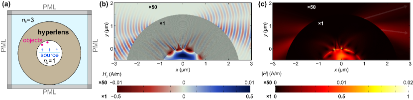
We have adapted the design principles elaborated in the previous section to the curvilinear geometry, starting with a multilayer structure similar to one used in 4(b) ( layers in total) and making the individual layer thickness 15 nm. The larger layer thicknesses were chosen in order to increase the total thickness of the lens, thereby increasing the magnification factor of the structure. Material parameters were also slightly modified in such a way that losses in metal were made slightly larger (, ), which was found to increase the quality of the images. The layers form concentric cylindrical shells with inner radius 1000 nm and outer radius 2500 nm.
The simulation set-up is also quite similar to the previous demonstration of the poor man’s hyperlens (see Section 2) except that the ambient space around the lens is now filled with a realistic medium with rather than with a fictitious one. Since the structure is now spatially finite rather than infinite, the supercell approach is no longer needed, and hence absorbing boundary conditions are used on all sides. In order to avoid numerical artifacts arising from the interaction of high- waves with PMLs, complete circular structure is enclosed in the simulation domain [see 5(a)]; the presence of losses in the HMM structure is expected to prevent the effects of round-trip wave propagation in the structure.
As before, the objects to be imaged are subwavelength-sized cylinders placed close to the inner surface of the hyperlens. They are illuminated by a beam (FWHM 666 nm) in the direction; in the simulation set-up used, this excitation is created by placing a surface current source in middle of the hyperlens, as shown in 5(a).
The simulation results are shown in 5(b–c). The field distribution map (5(b)) shows that the operation is quite similar to the planar poor man’s hyperlens considered above, with each object giving rise to a cone-like pattern in the hyperlens. However, the high- waves in these patterns are now transformed as they propagate outward, and can therefore be coupled out of the lens if the output medium has realistic index of refraction. This can be confirmed in the intensity map (5(c)), where it is seen that each object produces a pair of output beams present in the output medium. It can also be seen that the geometric transformation makes the distance between the image beams greater than between objects (e.g. almost 1 micron for 290 nm separation between objects), making the resulting subwavelength image suitable for further processing by conventional optics.
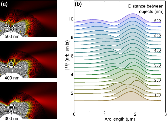
To further characterize the hyperlensing functionality of the proposed structure, we vary the distance between scatterers and analyze how this variation affects the fields in the image area. The results are shown in 6. It is seen that bringing the scatterers further apart causes a corresponding increase in the distance between the image points (6(a)), with the distance between the centroids of image points nearly proportional to the distance between objects. It can also be seen that well-resolved images can be formed for objects as close to each other as 175 nm apart (6(b)). However, it is seen that the quality of image deteriorates for distances lower than 300 nm, with fluctuating visibility of the image that prevents the two image points from being resolved at some values of inter-object separation. These fluctuations result from the interference of high- patterns inside the hyperlens. Above 300 nm separation, the subwavelength imaging functionality of the proposed hyperlens is fairly reliable.
The field and intensity profiles seen in 5 and 6 further bring out the drawback of operation outside of canalization regime. The existence of multiple image points per object (or, in the 3D geometry, an image cone) decreases the amount of useful signal and may necessitate the use of image restoration techniques. In addition, the inability to separate the signal from multiple objects inside the hyperlens gives rise to interference effects, which manifest in the image area as distortions. So one of the primary future tasks would be to minimize those interference effects.
Another challenge in the design of the DFHL is that, on the one hand, it should allow propagation of a broad range of high- waves at its inner surface while having strong attenuation for low- waves, so that subwavelength image is extracted and separated from background radiation. On the other hand, the waves at the outer surface should have sufficiently low -vectors in order to pass through to the surrounding medium. This tradeoff narrows down the range of high- waves taking part in the image formation, which limits the imaging resolution according to 3(b), and gives rise to the requirement that be greater (ideally, much greater) than . The account for losses, which affect higher- waves more strongly, is also detrimental, contributing to narrowing down of the allowed range of high- waves and lowering the image brightness. Together, these factors place a limit of on the magnification factor of the DFHL achievable by geometrical transformation alone.
We stress that the presented simulation results only constitute the proof-of-principle for the proposed concept of the DFHL. It is therefore expected that further optimization can improve the DFHL imaging performance. For example, higher magnification and better image quality may be possible with gradient structures where layer thicknesses would vary across the thickness of the lens, although such a structure would be more difficult to manufacture. Another promising optimization direction is to combine two hyperlens structures (BFHL and DFHL) in one device, along the same lines as the combination of a superlens and a hyperlens was used in 14. In such a hybrid device, the DFHL part could perform preliminary magnification along with background radiation filtering, after which the BFHL can perform the main magnification in the canalization regime.
5 Conclusions and outlook
In summary, we have proposed a concept for high-contrast subwavelength imaging (hyperlensing) of weakly scattering objects through the use of type-II rather than type-I HMM in the hyperlens, which prevents all propagating waves existing in the object area. The proposed dark-field hyperlens, so termed because its operating principle is similar to blocking incident light in dark-field optical microscopy17, only transmits high- waves stemming from subwavelength features of the sample (see 1). The resulting subwavelength image therefore has a much greater contrast than the one produced by a conventional hyperlens; in the presented numerical example the contrast enhancement by more that two orders of magnitude was demonstrated for subwavelength dielectric scatterers (see 4). Simulations further confirm the feasibility of the DFHL operation and present proof-of-principle DFHL design with demonstrated subwavelength imaging capability with weakly scattering objects illuminated by external light. This is in contrast with previous studies on the hyperlens 12, 13, 14 where the choice of the sample was intentionally made in such a way as to exclude background radiation.
The proposed concept, dark-field superresolving optical microscopy, can find many applications in biological imaging because it can be performed without the use of fluorescent markers and/or special sample preparation techniques. As a result, the proposed method can be used to obtain dynamic real-time images of weak-contrast subwavelength objects. The resulting possibility to see and investigate dynamic processes involving subwavelength-sized biological agents and macromolecules (including in vivo studies) can be enabling to modern life sciences. Finally, the possibility to reverse the operation of a hyperlens, which can be realized by virtue of the time-reversal symmetry of the Maxwell equations, can be used to focus light in a subwavelength scale and selectively excite a subwavelength object. This may bring about an even greater advance in experimental biology, making it possible to actively interfere with nanoscale biological agents while observing them.
This work has received financial support from the People Programme (Marie Curie Actions) of the European Union’s 7th Framework (EU FP7) Programme FP7-PEOPLE-2011-IIF under REA grant agreement No. 302009 (Project HyPHONE). One of us (T.R.) thanks the Archimedes Foundation for financial support (Kristjan Jaak scholarship).
Some movie files can be put here, such as an animation of what happens when the distance between scatterers varies. Our ”continuous separation graphs” can be there, too.
References
- Cai and Shalaev 2009 Cai, W.; Shalaev, V. Optical Metamaterials: Fundamentals and Applications; Springer, 2009
- Shalaev 2007 Shalaev, V. M. Nature Photonics 2007, 1, 41–48
- Pendry 2000 Pendry, J. B. Physical review letters 2000, 85, 3966
- Fang et al. 2005 Fang, N.; Lee, H.; Sun, C.; Zhang, X. Science 2005, 308, 534–537
- Liu et al. 2007 Liu, Z.; Durant, S.; Lee, H.; Pikus, Y.; Xiong, Y.; Sun, C.; Zhang, X. Optics express 2007, 15, 6947–6954
- Aydin et al. 2007 Aydin, K.; Bulu, I.; Ozbay, E. Applied physics letters 2007, 90, 254102
- Xiong et al. 2007 Xiong, Y.; Liu, Z.; Sun, C.; Zhang, X. Nano letters 2007, 7, 3360–3365
- Zhang and Liu 2008 Zhang, X.; Liu, Z. Nature materials 2008, 7, 435–441
- Jacob et al. 2006 Jacob, Z.; Alekseyev, L. V.; Narimanov, E. Optics express 2006, 14, 8247–8256
- Poddubny et al. 2013 Poddubny, A.; Iorsh, I.; Belov, P.; Kivshar, Y. Nature Photonics 2013, 7, 948–957
- Orlov et al. 2014 Orlov, A. A.; Iorsh, I. V.; Zhukovsky, S. V.; Belov, P. A. Photonics and Nanostructures – Fundamentals and Applications 2014, 12, 213–230
- Liu et al. 2007 Liu, Z.; Lee, H.; Xiong, Y.; Sun, C.; Zhang, X. science 2007, 315, 1686–1686
- Rho et al. 2010 Rho, J.; Ye, Z.; Xiong, Y.; Yin, X.; Liu, Z.; Choi, H.; Bartal, G.; Zhang, X. Nature communications 2010, 1, 143
- Cheng et al. 2013 Cheng, B. H.; Lan, Y.-C.; Tsai, D. P. Optics express 2013, 21, 14898–14906
- Li et al. 2009 Li, J.; Fok, L.; Yin, X.; Bartal, G.; Zhang, X. Nature materials 2009, 8, 931–934
- Andryieuski et al. 2012 Andryieuski, A.; Lavrinenko, A. V.; Chigrin, D. N. Physical Review B 2012, 86, 121108
- Benisty and Goudail 2012 Benisty, H.; Goudail, F. JOSA B 2012, 29, 2595–2602
- Leung and Chou 2011 Leung, B. O.; Chou, K. C. Appl. Spectrosc. 2011, 65, 967–980
- Ayas et al. 2013 Ayas, S.; Cinar, G.; Ozkan, A. D.; Soran, Z.; Ekiz, O.; Kocaay, D.; Tomak, A.; Toren, P.; Kaya, Y.; Tunc, I.; Zareie, H.; Tekinay, T.; Tekinay, A. B.; Guler, M. O.; Dana, A. Sci. Rep. 2013, 3
- Wong and Eleftheriades 2013 Wong, A. M.; Eleftheriades, G. V. Scientific reports 2013, 3
- Yang et al. 2014 Yang, H.; Moullan, N.; Auwerx, J.; Gijs, M. A. Small 2014, 10, 1712–1718
- Smith et al. 2004 Smith, D. R.; Schurig, D.; Mock, J. J.; Kolinko, P.; Rye, P. Applied Physics Letters 2004, 84, 2244–2246
- Kidwai et al. 2012 Kidwai, O.; Zhukovsky, S. V.; Sipe, J. E. Phys. Rev. A 2012, 85, 053842
- Zhukovsky et al. 2013 Zhukovsky, S. V.; Kidwai, O.; Sipe, J. E. Opt. Express 2013, 21, 14982–14987
- Jiang et al. 2013 Jiang, W. X.; Qiu, C.-W.; Han, T. C.; Cheng, Q.; Ma, H. F.; Zhang, S.; Cui, T. J. Advanced Materials 2013, 25, 6963–6968
- Guo et al. 2012 Guo, Y.; Newman, W.; Cortes, C. L.; Jacob, Z. Advances in OptoElectronics 2012, 2012, 1–9
- Zheludev 2008 Zheludev, N. I. Nature materials 2008, 7, 420–422
- Ishii et al. 2013 Ishii, S.; Kildishev, A. V.; Narimanov, E.; Shalaev, V. M.; Drachev, V. P. Laser & Photonics Reviews 2013, 7, 265–271
- Zhukovsky et al. 2014 Zhukovsky, S. V.; Andryieuski, A.; Sipe, J. E.; Lavrinenko, A. V. Physical Review B 2014, 90, 155429
- Ni et al. 2011 Ni, X.; Ishii, S.; Thoreson, M. D.; Shalaev, V. M.; Han, S.; Lee, S.; Kildishev, A. V. Optics express 2011, 19, 25242–25254