Commissioning of the new calorimeters of the KLOE-2 experiment
Abstract
Three new sub-detectors have been installed on May 2013 in the KLOE apparatus of Laboratori Nazionali di Frascati of INFN. Photon detection is improved by means of a small crystal calorimeter, named CCALT, in the very forward direction and of a tungsten-scintillating tile sampling device, named QCALT, instrumenting the low-beta quadrupoles of the accelerator. During the first DANE operations, some preliminary runs, both with and without collisions, have been acquired allowing the commissioning of new subdetectors. In this paper, we report a brief description of QCALT and CCALT and a summary of the commissioning phase.
PACS numbers come here
1 QCALT
In the old IP scheme of DANE, the inner focalizing quadrupoles had two surrounding calorimeters, named QCAL [1], covering a polar angle down to 21 degrees. Each calorimeter consisted of 16 azimuthal sectors composed by alternating layers of 2 mm lead and 1 mm BC408 scintillator tiles, for a total thickness of X0. The back bending fiber arrangement allowed the measurement of the longitudinal coordinate by time difference with a resolution of 13 cm. These calorimeters were characterized by a low light response (1-3 pe/mip/tile) due to the optical coupling in air between fivers and PMT, to the fiber length (2 m for each tile) and to the quantum efficiency of the used photomultipliers (standard bialkali with 20% QE).
The presence of a calorimeter in the quadrupoles region is needed to intercept photons coming from decays and lost in the beam pipe. Increased efficiency for these photons implies a strong reduction of the background in CP violating events such as . Moreover, high granularity in the calorimeter will help on reducing accidental contribution from machine background [2].
For the KLOE-2 upgrade [3, 4, 5] we have designed and built two new calorimeters, named QCALT [6]. The detector requirements can be summarised as: a realization of a high granularity calorimeters with sufficient , fast timing response with a time resolution better than plus some boundary conditions arising from the location of the existing detector: maximum length below 1 meter, maximum height 5 cm and photosensors working in B field.
1.1 QCALT design and components
QCALT consists of two dodecagonal sampling calorimeters covering the quadrupoles region close to the IP. Each module, 1/12 of one calorimeter, is composed of16 towers with 5 layers of 3.5 mm absorber and 5 scintillator tiles 5 mm thick (See Fig.1). The sampling absorber is made with a 90% tungsten and 10% copper alloy. Scintillator tiles are made using EJ-200 plastic scintillator produced by Eljen and painted using BC-620 refractive paint. Light from scintillator is routed outside via multi-cladding BCF-92 1mm round fibers inserted in a circular groove ensuring a fast emission time (5 ns/pe), long attenuation length and a large light yield with respect to standard single cladding fibers.
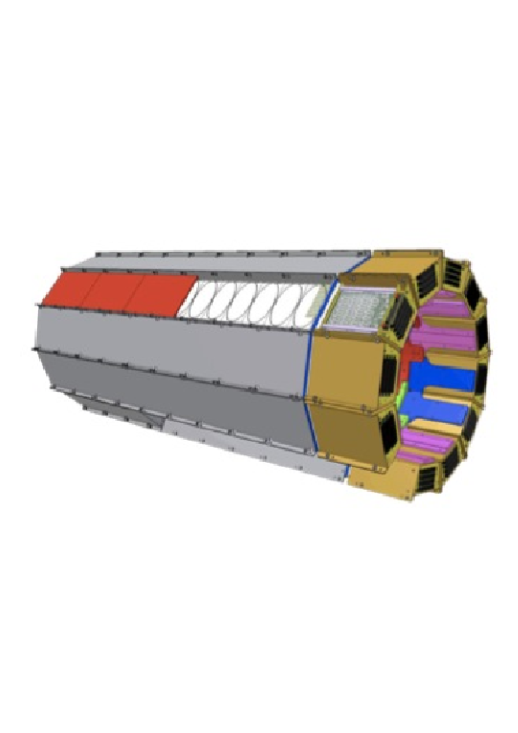
At one side of the calorimeter, fibers are collected and glued into a plastic holder polished with 0.05 mm planarity and coupled to an aluminum dioxide PCB where 80 SMD SiPM are bounded. Each tile is independently coupled to a photodetector ensuring 0.05 mm clearance in each direction.
1.2 QCALT photosensors and FEE
In the QCALT we use a custom SMD circular SiPM produced by FBK of 1.2 mm diameter, 25 m pixel size and PDE (photon detection efficiency) peaked at 480 nm. The 80 photodetectors for each module are bonded on an Alluminum PCB and covered with optical resin. The bias voltage required is between 30 and 35 V.
Each PCB is then connected to 4 boards, 20 channels/each, including 20 trans-impedance preamplifiers, HV regulators (0.1% precision, 0.01% stability) and single threshold discriminators with differential output. Each module requires a power consumption of 2 W. Boards are inserted in a brass Faraday cage with air cooling. Calorimeter reconstruction is based only on timing using multi-hit TDC with 0.5 ns resolution.
1.3 QCALT commissioning
The QCALT calorimeters have been installed on May 2013 while the FEE boards have been tested during each installation steps. At the end of the beam pipe insertion, we had less than 10 dead channels over about 1800 readout channels.
During first beam insertion, we have experienced heating problems due to insufficient cooling of the electronics. This problem has been solved in October 2013 with the installation of a dedicated air compressed line for both IT and QCALT cooling which decreases the SiPM temperature from 50∘ to 30∘ permitting normal operation.
A dedicated slow control for QCALT has been developed that allows single channel HV and threshold setting and temperature control.
Some preliminary runs, both with and without beam, have been collected with QCALT to test the complete FEE chain and SiPM functionality. Offline architecture has been developed permitting reconstruction of QCALT data also with other subdetectors.
Monte Carlo simulation of the entire QCALT has also been completed and is being integrated in the official KLOE-2 simulation framework.
During November 2014, as soon as DANE will resume operations, collision runs will be acquired to test the full functionality of the detector in collisions.
2 CCALT
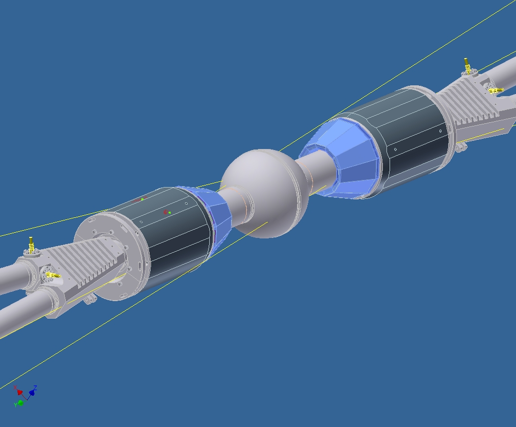
In the upgraded KLOE-2 detector we have introduced the CCALT [9] calorimeter between the interaction point, IP, and the first inner quadrupoles (See Fig. 2) to extend the angular coverage of the main electromagnetic calorimeter. The angular coverage extension, from a polar angle of 20∘ down to , will increase the multiphoton detection capability of the experiment enhancing the search reach for rare eta and kaon decays reconstruction, such as , , and prompt decay channels [7].
The basic layout of the calorimeter extension consists of two small barrels of LYSO crystals readout with silicon photosensors; aiming to achieve a timing resolution between 300 and 500 ps for 20 MeV photons. The first test of a (5.5613) cm3 prototype for such a detector was carried out at the Beam Test Facility of Laboratori Nazionali di Frascati of INFN.
2.1 CCALT: a Crystal Calorimeter with Time
The discussion of the previous section indicates that this calorimeter has to be very dense, with a small value of radiation length, , and Moliere radius, , not hygroscopic and with a large light output to improve photon detection efficiency at low energy (from 20 to 500 MeV). Moreover, the calorimeter has to be extremely fast in order to allow for prompt photon reconstruction. Preliminary simulation studies indicates the need to reach a time resolution of 300 500 ps for 20 MeV photons.
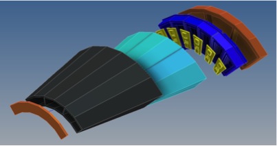
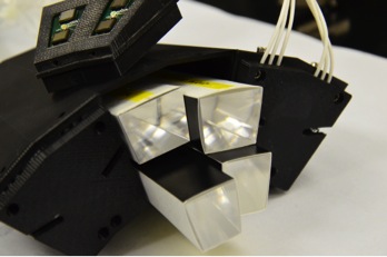
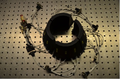
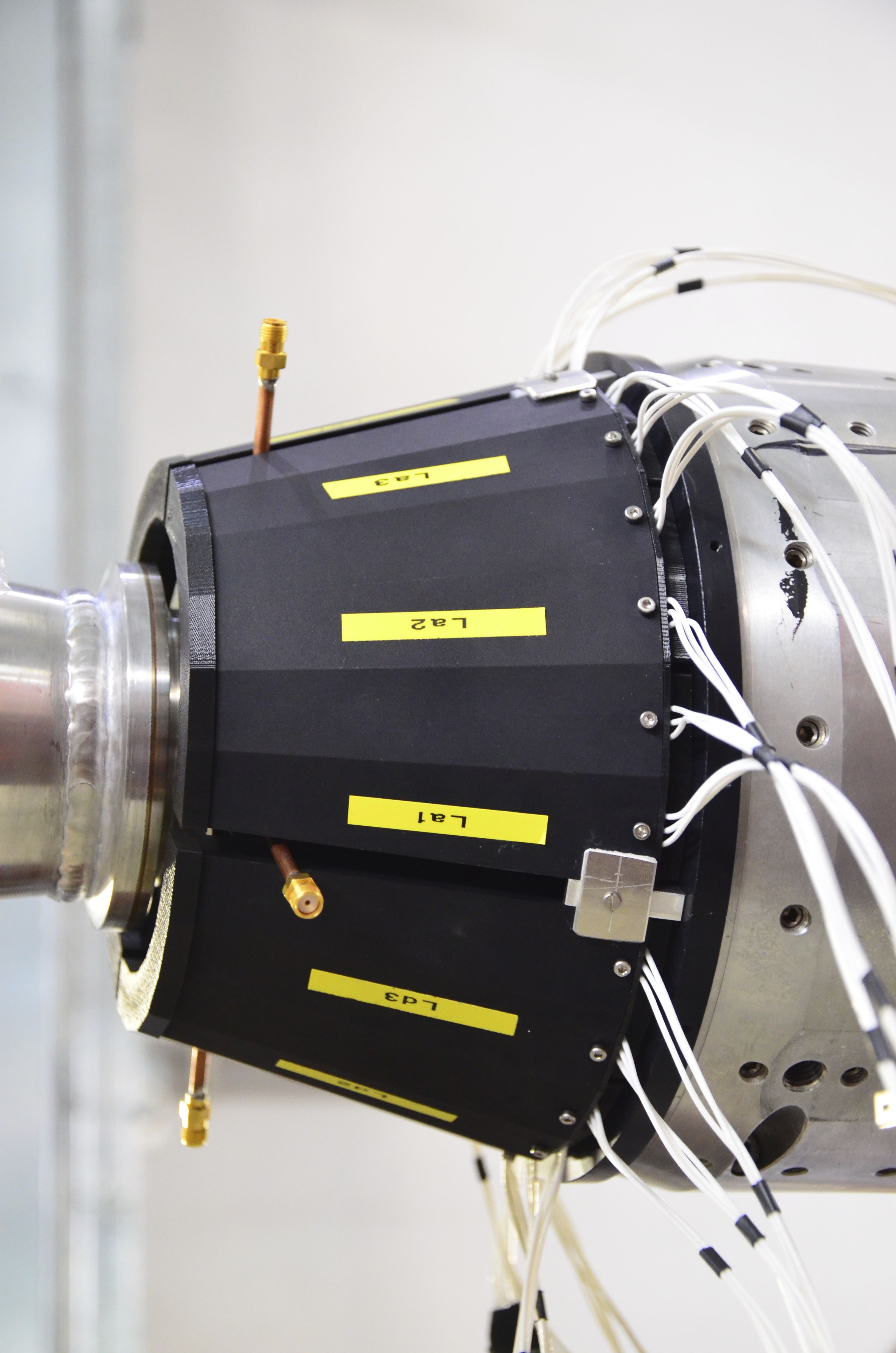
The detector layout consists of two concentrical barrels composed by 48 crystals each with transversal dimensions of 1.52 cm2 in the readout plane, mm2 in the front side and longitudinal length between 13 and 15 cm. The best crystal choice matching the requirements is provided by LYSO, which has () value of 1.1 (2 cm) and a scintillation emission time of 40 ns. Each side of the CCALT is composed by four shells made of aluminum, each constituted by three sectors containing a module with a granularity of 4 crystals. The shells have a projective shape from the interaction point outward. Each shell has been machined using electro discharge machining. The crystals building up a module are of two geometrical shapes (UP and DOWN type) and keep the projective geometry. An exploded view of the components of each shell is shown in Figure 3. The crystals are wrapped using a 3M super reflective tape, each pair of crystals is faced to a FEE board housing two SiPM and a LED for calibrating the photo device gain. In Figure 4 we show the shells composing half of the CCCALT (left) and its positioning over the beam pipe (right).
In the final location of the CCALT inside KLOE-2, the presence of an axial magnetic field of 0.52 kGauss forced the usage of silicon based photodetectors. We have used large area Advansid SiPM, with an active area of mm2. The timing and energy resolution properties of a LYSO crystal calorimeter readout with Silicon photosensors have been measured building a medium size crystal matrix prototype with transversal radius larger than 2 , longitudinal dimensions between 13 and 15 cm (corresponding to 11 12 of longitudinal containment). The prototype consisted of an inner matrix of 10 LYSO crystals readout by APD and an outer matrix, for leakage recovery. Each crystal was wrapped with 100 m of tyvek on the lateral faces, leaving free both the front and end faces, thus allowing one to bring calibration light pulses through an external LED and a fast change of the photosensors readout.

We have taken data at the Beam Test Facility, BTF, of LNF for two weeks in april 2009. In Fig. 5.left, we show the distribution of for a beam of 100 and 500 MeV respectively. In Fig. 5 (right), we show the energy dependence of the energy resolution measured on data which has been fit with the following equation: , where, accordingly to MC, we have fixed the constant term to be 5 %. We found and when using the gaussian fits to the spectra. We have then determined the position resolution by using the BPM of BTF and we observed a position resolution of 2.8 3 mm at 500 MeV.
The calorimeter timing performances have been measured after correcting, event by event, for the arrival time of the electrons in the LINAC spill. This was done by measuring the timing with the scintillators. The weighted energy average over all calorimeter, , was done after subtracting the average T0 of each cell. A clean gaussian response is observed with a time resolution, , of 49 ps ( 120 ps) at 500 MeV (100 MeV) after correcting for trigger jitter.
2.2 Test of single crystals with SiPM read-out
Due to space constraints and thermal considerations, the final choice for the read-out is large area (() mm2) SiPM from ADVANSID. This results in a loss of in time resolution, of which 2.5 due to the area reduction and 1.6 due to the lower quantum efficiency. The usage of SiPM still satisfies detector requirements, adding the possibility to increase read-out granularity due to the lower cost with respect to APD.
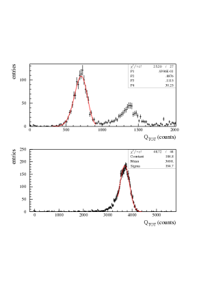
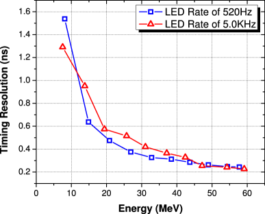
We have tested the timing performances and the dependence of the response on rate firing single crystals of () mm2 with a UV LED and reading them out with the ADVANSID SiPMs. Both time resolution and energy response are stable for different LED rates, up to 100-200 kHz. In Fig. 6, the achieved time resolution is shown as a function of the equivalent photon energy for 0.5 and 5 kHz LED rate. The energy distribution for one crystal is reported in Fig. 6. A 10% energy resolution in obtained at 511 keV.
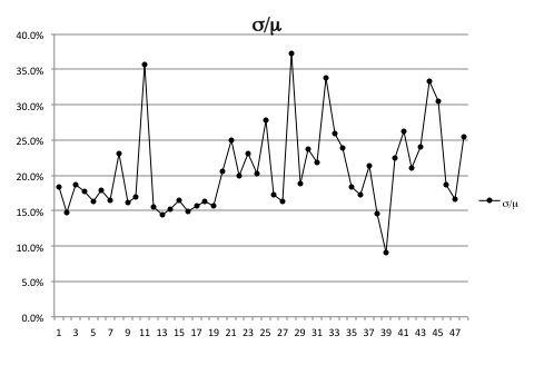
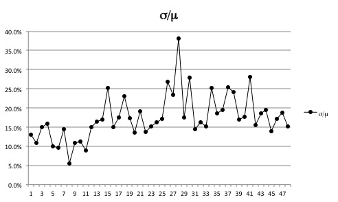
Prior to the assembling the calorimeter, all the crystals purchased from SICCAS have been tested using a 22Na source and PM read-out. The measured energy resolution is shown in Fig. 7; we rejected, and asked for replacement, crystals with a energy resolution .

2.3 Commissioning
The CCALT detector is installed over the beam pipe, the slow control for HV settings (0.1 precision and 0.01% stability of the SiPM) is working. All the channels are working and are being pulsed with LED and calibrated with cosmic runs. The CCALT channels have been included in the data acquisition and in the Offline chain of KLOE-2.
References
- [1] M.Adinolfi et al., NIM A483 (2002).
- [2] D. Babusci et al. Phys.Lett. B723 (2013) 54-60
- [3] D. Babusci et al. Nucl.Instrum.Meth. A617 81 (2010)
- [4] F. Archilli et al. Nucl.Instrum.Meth. A617 266 (2010)
- [5] A. Balla et al., JINST 9, C01014 (2014)
- [6] M.Ballaet al., NIM A718 (2013).
- [7] G. Amelino-Camelia et al., Eur. Phys. J. C 68 (2010) 619.
- [8] M. Cordelli, et al., Nucl. Instrum. Meth. A617 (2010) 109–112.
- [9] M.Cordelliet al., Conf. Ser. 293, 012010 (2011)