Coordinate Tomlinson-Harashima Precoding Design for Overloaded Multi-user MIMO Systems
Abstract
Tomlinson-Harashima precoding (THP) is a nonlinear processing technique employed at the transmit side to implement the concept of dirty paper coding (DPC). The perform of THP, however, is restricted by the dimensionality constraint that the number of transmit antennas has to be greater or equal to the total number of receive antennas. In this paper, we propose an iterative coordinate THP algorithm for the scenarios in which the total number of receive antennas is larger than the number of transmit antennas. The proposed algorithm is implemented on two types of THP structures, the decentralized THP (dTHP) with diagonal weighted filters at the receivers of the users, and the centralized THP (cTHP) with diagonal weighted filter at the transmitter. Simulation results show that a much better bit error rate (BER) and sum-rate performances can be achieved by the proposed iterative coordinate THP compared to the previous linear art.
Index Terms:
Tomlinson-Harashima precoding (THP), overloaded systems, coordinated beamforming.I Introduction
For the Multi-user MIMO (MU-MIMO) broadcast channel with independent and identically distributed (i.i.d.) Gaussian interference, its capacity region is achieved by the dirty paper coding (DPC) [1, 2]. The concept of DPC is originally proposed in [86] that the capacity of the broadcast channel is the same as if the interference was not present by setting the transmitted signal equal to the desired data minus the interference. The DPC theory, however, is not suitable for practical application due to the requirement of infinitely long codewords [4].
Tomlinson-Harashima precoding (THP) [87, 88] is a pre-equalization technique originally proposed for channels with intersymbol interference (ISI). Then, the THP technique was extended from temporal equalization to spatial equalization for MIMO precoding in [77, 8], where an equal number of transmit and receive antennas is assumed. Although THP still suffers a performance loss as refer to the theoretical upper bound achieved by DPC [9], it can work as a cost-effective replacement of DPC in practice by implementing a LQ decomposition [10, 11]. In the literature, however, the system dimensionality for implementing the THP algorithms is always set as the number of transmit antennas greater than or equal to the total number of receive antennas, which is termed as the dimensionality constraint in [12].
To overcome the dimensionality constraint for the precoding algorithms, a receive antenna selection method is proposed in [13]. Another approach is the coordinated beamforming (CBF) which employs iterative operations to jointly update the transmit-receive beamforming vectors [14]-[18]. The convergence behavior of the iterations is not considered in [14], and the coordinated transmission strategy in [15] only supports a single data stream to each user. A flexible coordinated beamforming (FlexCoBF) algorithm is proposed in [16]-[18] to support the transmission of multiple data streams to each user for linear precoding techniques [85].
Based on our previous work on FlexCoBF, an iterative coordinate nonlinear THP algorithm is proposed in this work. There are two THP structures according to the positions of the diagonal weighted filter, decentralized filters located at the receivers or centralized filters deployed at the transmitter, which are denoted as dTHP or cTHP, respectively [20, 21]. Most of the previous research works on THP, however, have only focused on one of the structures. In this work, we develop the iterative coordinate THP for both of the two THP structures. The main contributions of the work can be summarized as
-
1.
An iterative coordinate strategy is developed to solve the dimensionality constraint for the nonlinear THP algorithms.
-
2.
The proposed iterative coordinate THP algorithm supports the transmission of multiple data streams.
-
3.
The proposed iterative coordinate THP algorithm is developed for both cTHP and dTHP structures.
-
4.
Not only the sum-rate but also the BER performance are investigated.
This paper is organized as follows. The system model and the basics of THP techniques are described in Section II. The proposed iterative coordinated THP algorithm is described in detail in Section III. Simulation results and conclusions are presented in Section IV and Section V, respectively.
II System Model and THP Algorithms
II-A The MU-MIMO System Model
We consider an uncoded MU-MIMO broadcast system illustrated in Fig. 1 , with transmit antennas equipped at the base station (BS), users in the system each equipped with receive antennas, and the total number of receive antennas is . The combined transmit data streams are denoted as with , where is the total number of transmit data streams and is the number of th user’s transmit data streams. The combined channel matrix is denoted as and is the th user’s channel matrix.

Note that power-loading schemes [8] could be used to determine the number of data streams or allocate more power to a weaker user to improve the overall performance. However, for simplicity, we assume that no power loading between users and streams is performed.
II-B Two Basic THP Structures
Based on the knowledge of CSI at the transmit side, the interference of the parallel streams of a MU-MIMO system with spatial multiplexing can be subtracted from the current stream. This successive inter-user interference cancellation technique at the transmit side is known as THP. Generally, there are three filters to implement THP algorithm: the feedback filter , the feedforward filter , and the scaling filter . According to the position of , there are two THP structures, which are illustrated in Fig. 2 below. The decentralized THP (dTHP) employs (or sub-matrices of it) at the receivers, whereas the centralized THP (cTHP) uses at the transmitter.

(a) Decentralized THP: the scaling matrix is separately placed at the receivers.
(b) Centralized THP: the scaling matrix is placed at the transmitter.
The feedback filter is used to successively cancel the interference caused by the previous streams from the current stream. Therefore, the feedback filter should be a lower triangular matrix with ones on the main diagonal [8]. The feedforward filter is used to enforce the spatial causality and has to be implemented at the transmit side for MU-MIMO systems because the physically distributed users cannot be processed jointly. The scaling filter contains the corresponding weighted coefficient for each stream and thus it should have a diagonal structure. The quantity is the combined transmit signal vector after the feedback operation and is the combined transmit signal vector after precoding,
| (1) |
The filters of THP can be effectively obtained by implementing an LQ decomposition [21] on the combined channel matrix , that is
| (2) |
where is a lower triangular matrix and is a unitary matrix (by unitary we mean ). Therefore, the filters for the THP algorithms can be obtained as
| (3) | |||
| (4) | |||
| (5) |
where is the th diagonal element of the matrix .
From Fig. 2, the transmitted symbols are successively generated as
| (6) |
where is the th transmit data stream with variance and are the elements of in row and column . The transmit power is significantly increased as the amplitude of exceeds the modulation boundary by implementing the successive cancellation. A modulo operation , which is defined element-wise, is employed to reduce the amplitude of the channel symbol to the boundary of the modulation alphabet [22]
| (7) |
where is a constant for the periodic extension of the constellation. The specific value of depends on the chosen modulation alphabet. Common choices for are for QPSK symbols and in case of rectangular 16-QAM when the symbol variance is one. The modulo processing is equivalent to adding a perturbation vector to the transmit data , such that the modified transmit data are [21]
| (8) |
Thus, the initial signal constellation is extended periodically and the effective th transmit data symbols are taken from the expanded set.
The received signal for dTHP and cTHP, after the feedback, feedforward and the scaling filters, is respectively given by
| (9) |
| (10) |
where the quantity is the combined Gaussian noise vector with i.i.d. entries of zero mean and variance . The factor is used to impose the power constraint with being the average transmit power.
III Proposed Iterative Coordinated THP Algorithm
The above discussed original THP algorithms are only feasible under the dimensionality constraint that . In this section, the coordinate concept is developed for THP algorithms to overcome the dimensionality constraint.
For the case when , the MU-MIMO system cannot support the transmission of data streams. Assume the number of actually transmitted data streams is and it should satisfy , which the physical meaning is that the number of maximum transmitted data streams cannot beyond the number of transmit antennas . Then, a coordinate filter is introduced at each user to adjust the transmit-receive filters iteratively. The equivalent channel matrix is obtained as
| (11) |
In Fig. 2, the feedback processing is mathematically equivalent to an inversion operation . Therefore, the transmitted symbol can be rewritten as
| (12) |
Substitute the equation (12) into equations (9) and (10), the received signal for cTHP and dTHP can be respectively rewritten as
| (13) |
| (14) |
From the above equations (13) and (14), the MU-MIMO broadcast channel is transformed into effective parallel single-user MIMO (SU-MIMO) channels. Therefore, the multi-user interference (MUI) is enforced to zero at each user by the successively THP processing. In the proposed iterative coordinate THP algorithm, the coordinate filter at each receiver is initialized with random matrices. Then, iterative computations are employed to update the coordinate filter to enforce zero MUI constraint as suggested in equations (13) and (14). Assume the variable represents the iteration index, the proposed iterative coordinate THP algorithm is performed in 5 steps.
-
1.
Initialize the iteration index to zero and to random matrices. Set the constant as the threshold for iteratively enforce zero MUI constraint.
-
2.
Set and compute the equivalent channel matrix as
-
3.
Apply the LQ decomposition on the equivalent channel matrix to obtain the THP filters as
-
4.
Update the th combined coordinate filter as
-
5.
Track the alterations of the residual MUI after the THP processing as
where , and denotes the off-diagonal elements of the matrix . If the residual MUI is above the threshold , go back to step 2. Otherwise, convergence is achieved and the iterative procedure can be ended.
For setting the value of the threshold , we usually apply to effectively perform the proposed algorithm and also it is not necessary to set the threshold exactly equals to zero.
IV Simulation Results
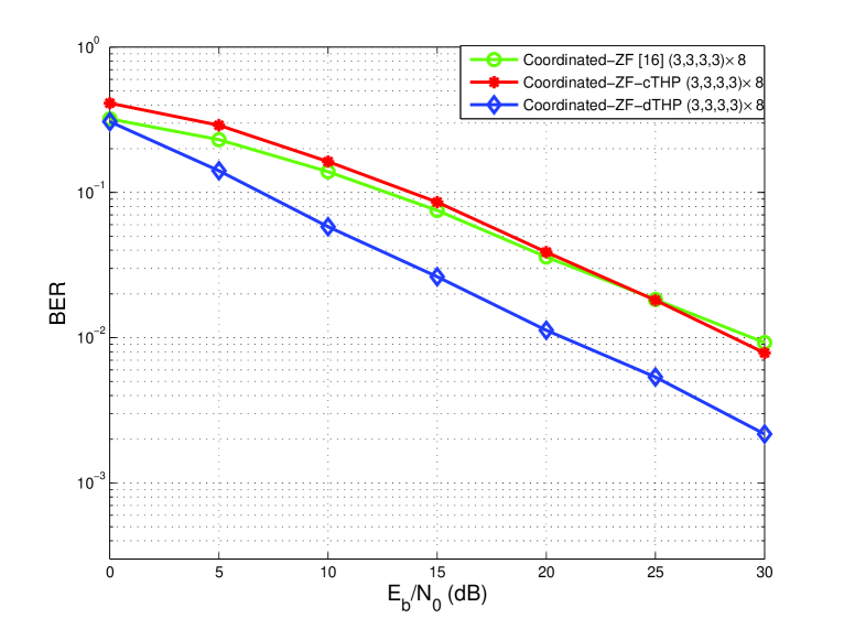
In this section, we assess the performance of the proposed iterative coordinate THP algorithms. A system with transmit antennas and users each equipped with receive antennas is considered; this scenario is denoted as the case. The quantity is defined as with being the number of information bits transmitted per channel symbol. Uncoded QPSK modulation scheme is employed in the simulations. The threshold is set to , and the maximum iteration number is restricted to . The channel matrix is assumed to be a complex i.i.d. Gaussian matrix with zero mean and unit variance.
For the MU-MIMO broadcast channel, the proposed iterative coordinate THP is implemented to support the maximum data streams at each user . The normal case of MU-MIMO broadcast channel is also simulated for comparison. The BER performance is illustrated in Fig. 3, from which we can find out that the precoding algorithms with iterative coordinate process suffer a performance loss compared to their counterparts implemented with normal case. The reason is that the introduced coordinate filter at each user brought extra noise enhancement for relaxing the dimensionality constraint. The proposed iterative coordinate dTHP achieves a gain of more than dB at BER of as compared to our previously proposed linear iterative coordinate ZF precoding. The iterative coordinate cTHP can still work well in this overloaded system but its performance is not so good as that of linear one at low s.
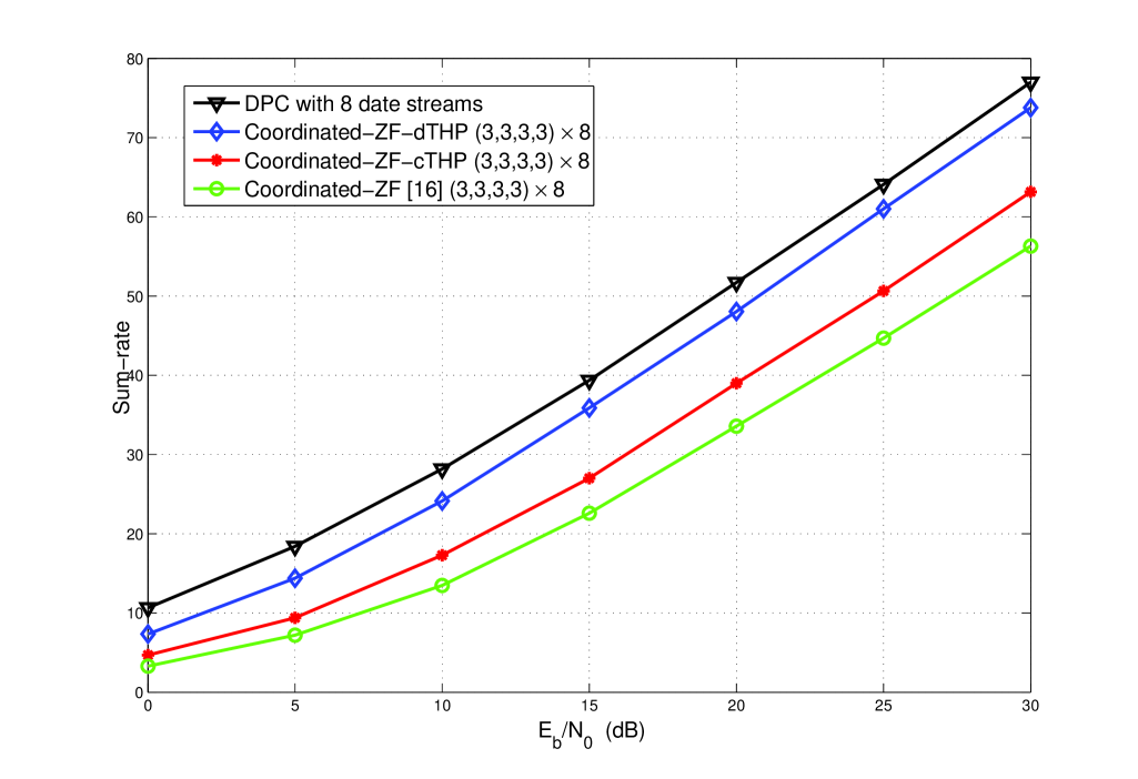
The sum-rate performance is displayed in Fig. 4. A much better sum-rate performance is achieved by both of the proposed iterative coordinate cTHP and dTHP than our previously proposed linear ZF precoding, and the sum-rate performance of iterative coordinate dTHP is very close to that of the DPC. Compared to the original dTHP implemented in the normal case, only a small loss when is over dB is performed. For the iterative coordinate cTHP, its sum-rate performance is not so sensitive as its BER performance compared to the original cTHP. Therefore, we have found that better BER and sum-rate performances can be achieved by the iterative coordinate dTHP as compared to the iterative coordinate cTHP. The BER performance of the iterative coordinate cTHP is more sensitive to the coordinate filter but its sum-rate performance maintains the robustness.
V conclusion
In this paper, an iterative coordinate THP algorithm have been proposed to relax the dimensionality constraint suffered by the original THP algorithms. Therefore, we consider the scenarios where . This condition is fulfilled in many scenarios that have been studied recently. For example, the users across cell borders have to be considered jointly by base stations (BSs) for coordinated multi-point (CoMP) transmission. Furthermore, when each user is equipped with multiple antennas, the BS simultaneously serves as many users as possible, which corresponds to a large number of receive antennas.
References
- [1] Q. Spencer, C. Peel, A. Swindlehurst and M. Haardt, ”An introduction to the multi-user MIMO downlink,” IEEE Commun. Mag., vol. 42, issue: 10, pp. 60-67, Oct. 2004.
- [2] H. Weingarten, Y. Steinberg and S. Shamai, ”The capacity region of the Gaussian multiple-input multiple-output broadcast channel,” IEEE Trans. Inform. Theory, vol. 52, no. 9, pp. 3936-3964, Sept. 2006.
- [3] M. Costa, ”Writing on dirty paper,” IEEE Trans. Inform. Theory, vol. 29, no. 3, pp. 439-441, May 1983.
- [4] A. Khina and U. Erez, ”On the Robustness of Dirty Paper Coding,” IEEE Trans. Commun., vol. 58, no. 5, May 2010.
- [5] M. Tomlinson, ”New automatic equaliser employing modulo arithmetic,” Electronic Letters, vol. 7, Mar. 1971.
- [6] H. Harashima and H. Miyakawa, ”Matched-transmission technique for channels with intersymbol interference,” IEEE Trans. Commun., vol. 20, Aug. 1972.
- [7] R. Fischer, C. Windpassinger, A. Lampe and J. Huber, ”Space-time transmission using Tomlinson-Harashima precoding,” in Proc. ITG Conf.on Source and Channel Coding (SCC), Berlin, Jan. 2002, pp. 139-147.
- [8] C. Windpassinger, R. Fischer, T. Vencel and J. Huber, ”Precoding in multiantenna and multiuser communications,” IEEE Trans. Wireless Commun., vol. 3, no. 4, Jul. 2004.
- [9] W. Y, D. Varodayan and J. M. Cioffi, ”Trellis and convolutional precoding for transmitter based interference presubstration,” IEEE Trans. Commun., pp. 1220-1230, Jul. 2005.
- [10] U. Erez, S. Shamai and R. Zamir, ”Capacity and lattice strategies for canceling known interference,” IEEE Trans. Inf. Theory, pp. 3820-3833, Nov. 2005.
- [11] K. Zu, R. C. de Lamare and M. Haardt, ”Multi-Branch Tomlinson-Harashima precoding for single-user MIMO systems,” in Proc. ITG/IEEE Workshop on Smart Antennas, Dresden, Germany, Mar. 2012.
- [12] Q. Spencer, A. Swindlehurst and M. Haardt, ”Zero-forcing methods for downlink spatial multiplexing in multiuser MIMO channels,” IEEE Trans. Signal Process., vol. 52, no. 2, pp. 461-471, Feb. 2004.
- [13] Z. Shen, R. Chen, J. Andrews, R. Health and B. Evans, ”Sum capacity of multiuser MIMO broadcast channels with block diagonalization,” IEEE Trans. Wireless Comun., vol. 6, no. 6, pp. 2040-2045, Jun. 2007.
- [14] Z. Zhou, W. Hardjawana and B. Vucetic, ”Iterative multiple beamforming algorithm for MIMO broadcast channels,” IEEE Commun. Lett., vol. 12, no. 10, pp. 743-745, Oct. 2008.
- [15] C. Chae, D. Marzzarese, T. Inoue and R. Health, ”Coordinated beamforming for the multiuser MIMO broadcast channel with limited feedforward,” IEEE Trans. Signal Process., vol. 56, no. 12, pp. 6044-6056, Dec. 2008.
- [16] B. Song and M. Haardt, ”Closed-form coordinated beamforming for multi-user MIMO broadcast channels,” in Proc. Wireless World Research Forum (WWRF), Beijing, China, 2009.
- [17] B. Song, F. Roemer and M. Haardt, ”Using a new structured joint congruence (STJOCO) transformation of Hermitian matrices for precoding in multi-user MIMO systems,” Proc. IEEE Int. Conf. on Acoustics, Speech, and Signal Processing (ICASSP), Dallas, TX, USA, Mar. 2010.
- [18] B. Song, F. Roemer and M. Haardt, ”Flexible coordinated beamforming (FlexCoBF) for the downlink of multi-user MIMO systems in single and clustered multiple cells,” Signal Processing, vol. 93, no. 9, pp. 2462-2473, Sept. 2013.
- [19] M. Joham, W. Utschick and J. A. Nossek, ”Linear transmit processing in MIMO communications systems,” IEEE Trans. Signal Process., vol. 53 no. 8, pp. 2700-2712, Aug. 2005.
- [20] M. Huang, S. Zhou and J. Wang, ”Analysis of Tomlinson-Harashima precoding in multiuser MIMO systems with imperfect channel state information,” IEEE Trans. Veh. Technol., vol. 57, no. 5, Sep. 2008.
- [21] K. Zu, R. C. de Lamare and M. Haart, ”Multi-branch Tomlinson-Harashima precoding design for MU-MIMO systems: Theory and algorithm,” IEEE Trans. Commun. (2nd round review), 2013.
- [22] F. Dietrich, P. Breun and W. Utschick, ”Robust Tomlinson-Harashima precoding for the wireless broadcast channel,” in IEEE Trans. Signal Process., vol. 55, no. 2, Feb. 2007.
- [23] P. Clarke, R. C. de Lamare, Joint Transmit Diversity Optimization and Relay Selection for Multi-relay Cooperative MIMO Systems Using Discrete Stochastic Algorithms, IEEE Communications Letters, vol. 15, p.p. 1035-1037, Oct. 2011.
- [24] P. Clarke and R. C. de Lamare, “Joint iterative power allocation and relay selection for cooperative MIMO systems using discrete stochastic algorithms,” 8th International Symposium on Wireless Communication Systems (ISWCS), vol., no., pp.432,436, 6-9 Nov. 2011
- [25] P. Clarke ad R. C. de Lamare, ”Transmit Diversity and Relay Selection Algorithms for Multi-relay Cooperative MIMO Systems”, IEEE Transactions on Vehicular Technology, vol. 61 , no. 3, March 2012, pp. 1084 - 1098.
- [26] R. C. de Lamare and S. Li, ”Joint Iterative Power Allocation and Interference Suppression Algorithms for Cooperative DS-CDMA Networks,” 2010 IEEE 71st Vehicular Technology Conference (VTC 2010-Spring), vol., no., pp.1,5, 16-19 May 2010
- [27] R. C. de Lamare, “Joint Iterative Power Allocation and Interference Suppression Algorithms for Cooperative Spread Spectrum Networks”, Proc. IEEE International Conference on Acoustics, Speech and Signal Processing, Dallas, USA, March 2010.
- [28] T. Wang, R. C. de Lamare, and P. D. Mitchell, ”Low-Complexity Set-Membership Channel Estimation for Cooperative Wireless Sensor Networks,” IEEE Trans. Veh. Technol., vol. 60, no. 6, May, 2011.
- [29] S. Li and R. C. de Lamare, “Frequency-domain adaptive detectors for single-carrier frequency-domain equalisation in multiuser direct-sequence ultra-wideband systems based on structured channel estimation and direct adaptation,” IET Communications, vol.4, no.13, pp. 1636-1650, September 2010.
- [30] R. C. de Lamare, “Joint iterative power allocation and linear interference suppression algorithms for cooperative DS-CDMA networks”, IET Communications, vol. 6, no. 13 , 2012, pp. 1930-1942.
- [31] T. Peng, R. C. de Lamare and A. Schmeink, “Adaptive Distributed Space-Time Coding Based on Adjustable Code Matrices for Cooperative MIMO Relaying Systems”, IEEE Transactions on Communications, vol. 61, no. 7, July 2013.
- [32] H. Yao and G. Wornell, ”Lattice reduction aided detectors for MIMO communication Systems,” in IEEE Proc. Globecom, Taipei, Taiwan, Nov. 2002.
- [33] C. Windpassinger and R. Fischer, ”Low-complexity near-maximum likelihood detection and precoding for MIMO systems using lattice reduction,” in Proc. IEEE Inf. Theory Workshop, Paris, France, pp. 345-348, Mar. 2003.
- [34] R. C. de Lamare and R. Sampaio-Neto, “Adaptive Reduced-Rank MMSE Filtering with Interpolated FIR Filters and Adaptive Interpolators”, IEEE Sig. Proc. Letters, vol. 12, no. 3, March, 2005.
- [35] R. C. de Lamare and Raimundo Sampaio-Neto, “Reduced-rank Interference Suppression for DS-CDMA based on Interpolated FIR Filters”, IEEE Communications Letters, vol. 9, no. 3, March 2005.
- [36] R. C. de Lamare and R. Sampaio-Neto, “Adaptive Interference Suppression for DS-CDMA Systems based on Interpolated FIR Filters with Adaptive Interpolators in Multipath Channels”, IEEE Transactions on Vehicular Technology, Vol. 56, no. 6, September 2007.
- [37] R. C. de Lamare and R. Sampaio-Neto, “Reduced-Rank Adaptive Filtering Based on Joint Iterative Optimization of Adaptive Filters”, IEEE Sig. Proc. Letters, Vol. 14, no. 12, December 2007.
- [38] R. C. de Lamare and R. Sampaio-Neto, “Reduced-Rank Space-Time Adaptive Interference Suppression With Joint Iterative Least Squares Algorithms for Spread-Spectrum Systems,” IEEE Transactions on Vehicular Technology, vol.59, no.3, March 2010, pp.1217-1228.
- [39] R. C. de Lamare and R. Sampaio-Neto, “Adaptive Reduced-Rank MMSE Parameter Estimation based on an Adaptive Diversity Combined Decimation and Interpolation Scheme,” Proc. IEEE International Conference on Acoustics, Speech and Signal Processing, April 15-20, 2007, vol. 3, pp. III-1317-III-1320.
- [40] R. C. de Lamare and R. Sampaio-Neto, “Adaptive Reduced-Rank Processing Based on Joint and Iterative Interpolation, Decimation, and Filtering,” IEEE Transactions on Signal Processing, vol. 57, no. 7, July 2009, pp. 2503 - 2514.
- [41] R. C. de Lamare, L. Wang, and R. Fa, “Adaptive reduced-rank LCMV beamforming algorithms based on joint iterative optimization of filters: Design and analysis,” Signal Processing, vol. 90, no. 2, pp. 640-652, Feb. 2010.
- [42] R. Fa, R. C. de Lamare, and L. Wang, “Reduced-Rank STAP Schemes for Airborne Radar Based on Switched Joint Interpolation, Decimation and Filtering Algorithm,” IEEE Transactions on Signal Processing, vol.58, no.8, Aug. 2010, pp.4182-4194.
- [43] R.C. de Lamare, R. Sampaio-Neto, M. Haardt, ”Blind Adaptive Constrained Constant-Modulus Reduced-Rank Interference Suppression Algorithms Based on Interpolation and Switched Decimation,” IEEE Transactions on Signal Processing, vol.59, no.2, pp.681-695, Feb. 2011.
- [44] S. Li, R. C. de Lamare, and R. Fa, “Reduced-Rank Linear Interference Suppression for DS-UWB Systems Based on Switched Approximations of Adaptive Basis Functions,” IEEE Transactions on Vehicular Technology, vol.60, no.2, pp.485-497, Feb. 2011.
- [45] Z. Xu and M.K. Tsatsanis, “Blind adaptive algorithms for minimum variance CDMA receivers,” IEEE Trans. Communications, vol. 49, No. 1, January 2001.
- [46] R. C. de Lamare and R. Sampaio-Neto, “Low-Complexity Variable Step-Size Mechanisms for Stochastic Gradient Algorithms in Minimum Variance CDMA Receivers”, IEEE Trans. Signal Processing, vol. 54, pp. 2302 - 2317, June 2006.
- [47] C. Xu, G. Feng and K. S. Kwak, “A Modified Constrained Constant Modulus Approach to Blind Adaptive Multiuser Detection,” IEEE Trans. Communications, vol. 49, No. 9, 2001.
- [48] Z. Xu and P. Liu, “Code-Constrained Blind Detection of CDMA Signals in Multipath Channels,” IEEE Sig. Proc. Letters, vol. 9, No. 12, December 2002.
- [49] R. C. de Lamare and R. Sampaio Neto, ”Blind Adaptive Code-Constrained Constant Modulus Algorithms for CDMA Interference Suppression in Multipath Channels”, IEEE Communications Letters, vol 9. no. 4, April, 2005.
- [50] R. C. de Lamare, M. Haardt and R. Sampaio-Neto, “Blind Adaptive Constrained Reduced-Rank Parameter Estimation based on Constant Modulus Design for CDMA Interference Suppression,” IEEE Transactions on Signal Processing, vol. 56., no. 6, June 2008.
- [51] R. C. de Lamare and R. Sampaio-Neto, “Blind adaptive MIMO receivers for space-time block-coded DS-CDMA systems in multipath channels using the constant modulus criterion”, IEEE Transactions on Communications, vol. 58, no. 1, pp. 21-27, January 2010.
- [52] L. Wang, R. C. de Lamare and M. Yukawa, “Adaptive reduced-rank constrained constant modulus algorithms based on joint iterative optimization of filters for beamforming”, IEEE Transactions on Signal Processing, vol.58, no. 6, pp. 2983-2997, June 2010.
- [53] L. Wang and R. C. de Lamare, “Adaptive constrained constant modulus algorithm based on auxiliary vector filtering for beamforming”, IEEE Transactions on Signal Processing, vol. 58, no. 10, pp. 5408-5413, October 2010.
- [54] L. Wang and R. C. de Lamare, “Constrained adaptive filtering algorithms based on conjugate gradient techniques for beamforming”, IET Signal Processing, vol. 4, no. 6, pp. 686-697, December 2010.
- [55] P. Clarke and R. C. de Lamare, “Low-complexity reduced-rank linear interference suppression based on set-membership joint iterative optimization for DS-CDMA systems”, IEEE Transactions on Vehicular Technology, vol. 60, no. 9, pp. 4324-4337, November 2011.
- [56] R. C. de Lamare and P. S. R. Diniz, “Set-membership adaptive algorithms based on time-varying error bounds for CDMA interference suppression,” IEEE Trans. Vehicular Technology, vol. 58, pp. 644-654, Feb. 2009.
- [57] R. C. de Lamare and P. S. R. Diniz, “Blind Adaptive Interference Suppression Based on Set-Membership Constrained Constant-Modulus Algorithms With Dynamic Bounds,” IEEE Transactions on Signal Processing, vol.61, no.5, pp.1288-1301, March 2013.
- [58] M. L. Honig and J. S. Goldstein, “Adaptive reduced-rank interference suppression based on the multistage Wiener filter,” IEEE Trans. on Communications, vol. 50, no. 6, June 2002.
- [59] Y. Sun, V. Tripathi, and M. L. Honig, ”Adaptive, Iterative, Reduced-Rank (Turbo) Equalization”, IEEE Trans. on Wireless Communications, Vol. 4, No. 6, pp. 2789-2800, Nov. 2005.
- [60] Y. Cai and R. C. de Lamare, ”Adaptive Linear Minimum BER Reduced-Rank Interference Suppression Algorithms Based on Joint and Iterative Optimization of Filters,” IEEE Communications Letters, vol.17, no.4, pp.633,636, April 2013.
- [61] R. C. de Lamare and R. Sampaio-Neto, “Reduced-Rank Adaptive Filtering Based on Joint Iterative Optimization of Adaptive Filters, ” IEEE Signal Processing Letters, Vol. 14 No. 12, December 2007, pp. 980 - 983.
- [62] L. Wang, R. C. de Lamare and M. Haardt, ”Reduced-rank DOA estimation based on joint iterative subspace recursive optimization and grid search,” 2010 IEEE International Conference on Acoustics Speech and Signal Processing (ICASSP), vol., no., pp.2626,2629, 14-19 March 2010
- [63] R. C. de Lamare and R. Sampaio-Neto, “Adaptive Reduced-Rank Processing Based on Joint and Iterative Interpolation, Decimation, and Filtering,” IEEE Transactions on Signal Processing, vol. 57, no. 7, July 2009, pp. 2503 - 2514.
- [64] R. C. de Lamare and R. Sampaio-Neto, “Reduced-Rank Space-Time Adaptive Interference Suppression With Joint Iterative Least Squares Algorithms for Spread-Spectrum Systems,” IEEE Transactions on Vehicular Technology, vol.59, no.3, March 2010, pp.1217-1228.
- [65] R. C. de Lamare and R. Sampaio-Neto, “Adaptive reduced-rank equalization algorithms based on alternating optimization design techniques for MIMO systems”, IEEE Transactions on Vehicular Technology, vol. 60, no. 6, 2482-2494, 2011.
- [66] R. C. de Lamare, R. Sampaio-Neto, “Adaptive MBER decision feedback multiuser receivers in frequency selective fading channels”, IEEE Communications Letters, vol. 7, no. 2, Feb. 2003, pp. 73 - 75.
- [67] R.C. de Lamare, R. Sampaio-Neto, A. Hjorungnes, “Joint iterative interference cancellation and parameter estimation for cdma systems”, IEEE Communications Letters, vol. 11, no. 12, December 2007, pp. 916 - 918.
- [68] R. C. de Lamare, R. Sampaio-Neto, Minimum Mean-Squared Error Iterative Successive Parallel Arbitrated Decision Feedback Detectors for DS-CDMA Systems, IEEE Trans. on Commun., vol. 56, p.p. 778-789, May 2008.
- [69] A. Rontogiannis, V. Kekatos, and K. Berberidis,” A Square-Root Adaptive V-BLAST Algorithm for Fast Time-Varying MIMO Channels,” IEEE Signal Processing Letters, Vol. 13, No. 5, pp. 265-268, May 2006.
- [70] R. Fa, R. C. de Lamare, “Multi-Branch Successive Interference Cancellation for MIMO Spatial Multiplexing Systems”, IET Communications, vol. 5, no. 4, pp. 484 - 494, March 2011.
- [71] P. Li, R. C. de Lamare and R. Fa, “Multiple Feedback Successive Interference Cancellation Detection for Multiuser MIMO Systems,” IEEE Transactions on Wireless Communications, vol. 10, no. 8, pp. 2434 - 2439, August 2011.
- [72] P. Li and R. C. de Lamare, ”Adaptive Decision-Feedback Detection With Constellation Constraints for MIMO Systems”, IEEE Transactions on Vehicular Technology, vol. 61, no. 2, 853-859, 2012.
- [73] R. C. de Lamare, ”Adaptive and Iterative Multi-Branch MMSE Decision Feedback Detection Algorithms for Multi-Antenna Systems”, IEEE Transactions on Wireless Communications, vol. 14, no. 10, October 2013.
- [74] P. Li and R. C. de Lamare, “Distributed Iterative Detection With Reduced Message Passing for Networked MIMO Cellular Systems,” IEEE Transactions on Vehicular Technology, vol.63, no.6, pp.2947,2954, July 2014.
- [75] Y. Cai and R. C. de Lamare, ”Adaptive Space-Time Decision Feedback Detectors with Multiple Feedback Cancellation”, IEEE Transactions on Vehicular Technology, vol. 58, no. 8, October 2009, pp. 4129 - 4140.
- [76] J. Liu, R. C. de Lamare, “Low-Latency Reweighted Belief Propagation Decoding for LDPC Codes,” IEEE Communications Letters, vol. 16, no. 10, pp. 1660-1663, October 2012.
- [77] R. Fischer, C. Windpassinger, ”Improved MIMO precoding for decentralized receivers resembling concepts from lattice reduction,” in Proc. IEEE Global Telecommun. Conf., San Francisco, CA, USA, pp.1852-1856, Dec. 2003.
- [78] N. Song, R. C. de Lamare, M. Haardt, and M. Wolf, “Adaptive Widely Linear Reduced-Rank Interference Suppression based on the Multi-Stage Wiener Filter,” IEEE Transactions on Signal Processing, vol. 60, no. 8, 2012.
- [79] C. Windpassinger, R. Fischer and J. Huber, ”Lattice reduction aided broadcast precoding,” IEEE Trans. Commun., vol. 52, no. 12, pp. 2057-2060, Dec. 2004.
- [80] Y. Cai, R. C. de Lamare and R. Fa, “Switched interleaving techniques with limited feedback for interference mitigation in DS-CDMA systems,” IEEE Trans. Commun., vol. 59, no. 7, pp. 1946-1956, July 2011.
- [81] Y. Cai, R. C. de Lamare and D. Le Ruyet, “Transmit Processing Techniques Based on Switched Interleaving and Limited Feedback for Interference Mitigation in Multiantenna MC-CDMA Systems,” IEEE Transactions on Vehicular Technology, vol.60, no.4, pp.1559,1570, May 2011.
- [82] K. Zu and R. C. de Lamare, ”Lattice reduction-aided preprocessing and detection techniques for MU-MIMO in broadcast,” in European Wireless Conf., Vienna, Austria, Apr. 2011.
- [83] K. Zu, R. C. de Lamare, ”Low-Complexity Lattice Reduction-Aided Regularized Block Diagonalization for MU-MIMO Systems”, IEEE Commun. Lett., vol. 16, no. 6, June 2012, pp. 925-928.
- [84] K. Zu, R. C. de Lamare and M. Haardt, ”Generalized design of low-complexity block diagonalization type precoding algorithms for multiuser MIMO systems”, IEEE Trans. Commun., vol. 61, no. 10, Oct. 2013.
- [85] M. Joham, W. Utschick and J. A. Nossek, ”Linear transmit processing in MIMO communications systems,” IEEE Trans. Signal Process., vol. 53 no. 8, pp. 2700-2712, Aug. 2005.
- [86] M. Costa, ”Writing on dirty paper,” IEEE Trans. Inform. Theory, vol. 29, no. 3, pp. 439-441, May 1983.
- [87] M. Tomlinson, ”New automatic equaliser employing modulo arithmetic,” Electronic Letters, vol. 7, Mar. 1971.
- [88] H. Harashima and H. Miyakawa, ”Matched-transmission technique for channels with intersymbol interference,” IEEE Trans. Commun., vol. 20, Aug. 1972.
- [89] K. Zu, R. C. de Lamare and M. Haardt, “Multi-Branch Tomlinson-Harashima Precoding Design for MU-MIMO Systems: Theory and Algorithms,” IEEE Transactions on Communications, vol.62, no.3, pp.939,951, March 2014.
- [90] L. Zhang, Y. Cai, R. C. de Lamare and M. Zhao, “Robust Multibranch Tomlinson–Harashima Precoding Design in Amplify-and-Forward MIMO Relay Systems,” IEEE Transactions on Communications, vol.62, no.10, pp.3476,3490, Oct. 2014.
- [91] B. Hochwald, C. Peel and A. Swindlehurst, ”A vector-perturbation technique for near capacity multiantenna multiuser communication - Part II: Perturbation,” IEEE Trans. Commun., vol. 53, no. 3, Mar. 2005.
- [92] C. B. Chae, S. Shim and R. W. Heath, ”Block diagonalized vector perturbation for multiuser MIMO systems,” IEEE Trans. Wireless Commun., vol. 7, no. 11, pp. 4051 - 4057, Nov. 2008.
- [93] Y. H. Gan, C. Ling, and W. H. Mow, ”Complex lattice reduction algorithm for low-complexity full-diversity MIMO detection,” IEEE Trans. Sig. Process., vol. 57, no. 7, pp. 2701 - 2710, Jul. 2009.
- [94] D. Wübben, R. Böhnke, V. Kühn, and K. Kammeyer, ”Near-maximum-likelihood detection of MIMO systems using MMSE-based lattice-reduction,” in ICC’04, pp. 798-802, Jun. 2004.
- [95] K. Zu and R. C. de Lamare ”Switched lattice reduction-aided detection techniques for MIMO systems”, Sensor Signal Processing for Defence Conf., London, UK, Sep. 2011.
- [96] M. Taherzadeh, A. Mobasher and A. K. Khandani, ”LLL reduction achieves the receiver diversity in MIMO decoding”, IEEE Trans. Inf. Theory, vol. 53, no. 12, Dec. 2007.
- [97] N. Song, W. U. Alokozai, R. C. de Lamare and M. Haardt, “Adaptive Widely Linear Reduced-Rank Beamforming Based on Joint Iterative Optimization,” IEEE Signal Processing Letters, vol.21, no.3, pp. 265-269, March 2014.
- [98] R. C. de Lamare and R. Sampaio-Neto, “Sparsity-Aware Adaptive Algorithms Based on Alternating Optimization and Shrinkage,” IEEE Signal Processing Letters, vol.21, no.2, pp.225,229, Feb. 2014.
- [99] H. Ruan and R. C. de Lamare, “Robust Adaptive Beamforming Using a Low-Complexity Shrinkage-Based Mismatch Estimation Algorithm,” IEEE Signal Processing Letters, vol.21, no.1, pp.60,64, Jan. 2014.