Overcoming black body radiation limit in free space: metamaterial superemitter
Abstract
Here, we demonstrate that the power spectral density of thermal
radiation at a specific wavelength produced by a body of finite
dimensions set up in free space under a fixed temperature could be
made theoretically arbitrary high, if one could realize double
negative metamaterials with arbitrary small loss and arbitrary high
absolute values of permittivity and permeability (at a given
frequency). This result refutes the widespread belief that Planck’s
law itself sets a hard upper limit on the spectral density of power
emitted by a finite macroscopic body whose size is much greater that
the wavelength. Here we propose a physical realization of a
metamaterial emitter whose spectral emissivity can be greater than
that of the ideal black body under the same conditions. Due to the
reciprocity between the heat emission and absorption processes such
cooled down superemitter also acts as an optimal sink for the
thermal radiation — the “thermal black hole” — which
outperforms Kirchhoff-Planck’s black body which can absorb only the
rays directly incident on its surface. The results may open a
possibility to realize narrowband super-Planckian thermal radiators
and absorbers for future thermo-photovoltaic systems and other devices.
Keywords: metamaterial, thermal radiation, black body.
pacs:
44.40.+a, 78.67.Pt, 42.25.Fx1 Introduction
The ability of a hot body to emit thermal electromagnetic radiation is related to its ability to absorb incident electromagnetic waves at the same frequencies. G. Kirchhoff in 1860 introduced the theoretical concept of an ideal black body, which “completely absorbs all incident rays” [1]. This concept was later adopted by M. Planck [2]. It appears that since that time there has been a general belief that no macroscopic body can emit more thermal radiation than the corresponding same-shape and size ideal black body at the same temperature. For example, in a recent paper [3] one reads, “any actual macroscopic thermal body cannot emit more thermal radiation than a blackbody.” Equivalent statements can be found in commonly used text books, for example, in the well-known book by Bohren and Huffman [4] it is stated that “…the emissivity of a sufficiently large sphere is not greater than 1. Thus, if the radiating sphere radius is much larger than the wavelength, the radiation above the black body limit is impossible.”
On the other hand, recently there has been increasing number of publications discussing so-called super-Planckian thermal radiation, when the power emitted by a hot body per unit area per unit wavelength exceeds the one predicted by Planck’s black body law. In a great deal of such works, the thermal emission into the electromagnetic near-field is considered, when the bodies that exchange radiative heat are separated by a distance significantly smaller than the wavelength (on the order of or less). Such emission can easily overcome the black body limit, because oscillators in bodies separated by subwavelength gaps interact through the near (i.e., Coulomb) electric field, and, when close enough to the emitting object, such a field is much stronger than the wave field.
Besides the near field transfer, there are also works — quite surprising for an unprepared reader — which report super-Planckian emission in far-field in free-space. In order to avoid confusion we must first agree on the terminology, because it appears that, currently, in the literature there is no consensus on the meaning of the super-Planckian radiation in this case. In this paper, we use this terminology exclusively for bodies of finite dimensions. When such an object acts as a source of thermal radiation, its spectral radiance , i.e., the amount of power radiated per wavelength interval , projected emitting area , and solid angle :
| (1) |
is sub-Planckian or super-Planckian depending on the choice of the area . If by definition is chosen to coincide with emitter’s geometric projected area: , then, given the reciprocal nature of the radiative heat emission and absorption processes, one has to admit that the spectral radiance of bodies characterized with the effective absorption cross section such that must be super-Planckian, because for the ideal black body .
Such definition explains the known fact that an optically small body can emit more than a black body of a similar size. Indeed, a small particle may absorb much more power than one would expect from its size, because a particle with radius may have the absorption cross section much larger than its geometric cross section . For a dielectric or plasmonic sphere, this is understood as a consequence of Mie’s (or respective plasmonic) resonances, at which the absorption cross section may outnumber by a large factor. For instance, for a single-mode dipole particle the ultimate absorption cross section equals (e.g. Ref. [5]), which is much larger than if . The absorption cross section can be further increased if the incident field couples to many resonant modes, e.g. Refs. [6, 7, 8, 9]. Similarly, resonant absorption by shape irregularities with curvature radius on a surface of a large body [10] makes the absorption cross section associated with an irregularity larger than its geometric cross section.
However, the known literature does not provide a definite answer to the main question of this article, namely, up to which degree the spectral density of power emitted by an optically large body can be larger than the one produced by the black body of the same dimensions under the same thermal conditions? In other words, how prominent can be the super-Planckian free-space radiation effect mentioned above in bodies whose size is much greater than the wavelength?
In fact, there is no agreement in the current literature even on whether such super-Planckian emission into free space is physically allowed — in particular, by thermodynamical considerations, — in a scenario with an optically large body emitting. For instance, in Ref. [11] it is argued that such emission would violate the second law of thermodynamics, but is this indeed the case?
In this paper, unlike previous works on related subjects, we consider a theoretical possibility to obtain free-space omnidirectional super-Planckian radiation from a finite macroscopic body with characteristic radius . This implies an important question — if there can exist optically large isotropic emitters with effective spectral emissivity greater than unity, when compared to Kirchhoff-Planck’s black body of the same size. In order to answer this question, we go over the usual assumption that an emitting body is composed of homogeneous materials with positive permittivities and permeabilities at the wavelength of interest. We show that if these restrictions are removed, there are no compelling reasons why a specially crafted metamaterial [12] object cannot produce a higher radiated spectral power at a given wavelength than the respective black body, even when object’s diameter is significantly greater than the wavelength.
Moreover, here we prove that the spectral power produced by a double-negative metamaterial emitter can be made theoretically arbitrary high at any given frequency, independently of the physical size of the emitter, under the condition that arbitrarily low loss tangent values and arbitrarily high absolute values of the permittivity and permeability are attainable. When cooled, such objects act as “thermal black holes” which absorb much more power than is incident directly on their surfaces. For instance, in a plane wave illumination scenario, they absorb (theoretically) the whole infinite power carried by such a wave (of infinite extent in space).
We prove that existence of such superemitters (and superabsorbers) contradicts neither the second law of thermodynamics, nor Kirchhoff’s law of thermal radiation when the latter is properly amended. In particular, we show that the super-Planckian part of the thermal flux in the vicinity of a superemitter is transferred by resonant tunneling of photons associated with high-order, highly reactive spatial harmonics (essentially, dark modes) of emitter’s fluctuating field. Due to this process, the effective spectral emissivity of such emitter when compared to Kirchhoff-Planck’s black body of the same size is greater than unity. This is physically possible because effective absorptivity of this object is as well greater than unity, which just means that it receives per unit area of its surface more spectral power than a Kirchhoff-Planck’s black body of the same radius under the same conditions.
Note that earlier studies establishing the widely accepted limitations are based on an assumption that the ideal Kirchhoff-Planck black body is the ultimately effective absorber. However, such a body perfectly absorbs only the rays which are falling directly on its surface [1]. Furthermore, we may recall the known result from the electromagnetic theory which states that there is no upper limit on the effective area of an antenna, even when the physical dimensions of the antenna are constrained [7, 13], and the equivalent results in diffraction theory [14] and acoustics [6]. In particular, this means that a finite-size antenna loaded with a conjugate-matched load , where is the complex input impedance of the antenna, in principle, can absorb all the power carried by a plane wave incident from the direction of antenna’s main beam, and thus — for this direction of incidence — can be infinitely more efficient in absorption than the ideal black body.
Similarly, the resonant photon tunneling effect which enables super-Planckian radiation occurs when the emitter is conjugate-impedance matched to a large set of the free space modes, including both bright (propagating) and dark (nearly evanescent) modes. As will be seen from the following, this effect is inherently narrowband due to highly reactive nature of the electromagnetic field associated with the dark modes. Let us note, however, that narrowband thermal radiation is the key prerequisite for advanced thermo-photovoltaic systems (TPVS). For instance, reducing relative bandwidth to less than 10% practically eliminates the Shottky-Queisser limit related to the dissipation of the excessive photon energy in semiconductors [15]. The nearly monochromatic thermal radiation is the primary target for solar TPVS, where the narrowband thermal emitters already allow the energy conversion efficiency to approach the thermodynamic limit [16]. Note that in all known works on solar TPVS the spectral maximum of this narrow-band thermal radiation is below the conventional Planckian spectral value [17].
In contrast, when a wide-band gain in thermal emission is needed, it can be achieved by covering emitters with transparent dielectric shells [3], or with shells made of hyperbolic metamaterials [18]. The radiation enhancement in these cases can be explained by an increase in the Purcell factor associated with elementary sources of thermal radiation placed inside such shells [18]. However, note that such non-resonant, broadband enhancers which essentially operate as optical collimators may not increase the effective emitter size beyond the size of the transparent shell itself. This means that the emitted power in such systems never exceeds the power radiated by a black body with the radius equal to the outer radius of the shell. Thus, the thermal radiation flux produced at the output of the shell is sub-Planckian. Furthermore, thermal radiation from an unbounded planar interface with a generic photonic crystal has been numerically studied in Ref. [19], and the results show that the power radiated from an infinite planar surface does not go over the black body limit.
Thus, it is important to investigate, both from the theoretical and practical points of view, the possibilities in realizing omnidirectional thermal super-Planckian emitters and confirm that their existence does not violate fundamental laws of physics, as well as to find the required properties of metamaterials from which such thermal superemitters can be made. These are the goals of this work.
2 The content of this paper
The paper is organized as follows. In Sec. 3 we outline the equivalent circuit model [20] that we use in radiative thermal flux calculations. It has been proven [20] that this approach is fully equivalent in its predictive power to the more common theories operating with distributed thermal-fluctuating currents. Using this model, in Sec. 4 we consider general conditions which maximize the radiative heat flux between a hot body and its environment.
In Sec. 5 we study the thermal radiation produced by finite-size bodies in free space and introduce the concept of the ideal conjugate-matched emitter. Such a truly super-Planckian emitter is able to radiate efficiently to the entire infinite set of free-space photonic states, infinitely outperforming a black body emitter of the same dimensions.
In Sec. 6 we consider plane wave scattering on a finite-size body and prove that its scattering, absorption, and extinction cross sections tend to infinity under the perfect conjugate matching condition of Sec. 5, independently of the size of the body.
In Sec. 7 we show that the second law of thermodynamics is not violated by finite-size emitters with effective spectral emissivity greater than unity. We also propose an amendment to Kirchhoff’s law of thermal radiation in order to incorporate such emitters into the existing theory.
In Sec. 8 we search for a physical realization for the conjugate-matched emitter. A possible realization — which we call metamaterial thermal black hole — is obtained in the form of a core-shell double-negative (DNG) metamaterial structure.
3 Electromagnetic theory of thermal radiation: circuit model approach
The approach of Ref. [20] allows one to reduce a full-wave thermal emission problem to a set of circuit theory problems operating with effective fluctuating voltages and currents instead of the electromagnetic fields. This approach is based on expanding the emitted field at a given frequency into a suitable series of linearly independent, orthogonal spatial harmonics, and characterizing each of these harmonics with the equivalent circuit model parameters, such as complex wave impedance, voltage and current. The electromagnetic interaction of a hot emitter with the surrounding space can be expressed in this language at each of the mentioned harmonics with an equivalent circuit shown in Fig. 1(a). In this circuit, represents the equivalent complex impedance of emitter’s body for a given spatial harmonic of the radiated field, at the frequency . Respectively, is the equivalent complex impedance of the surrounding space for the same mode, which, in case of the free space, is simply the wave impedance of the corresponding mode: . The effect of thermal fluctuations in this circuit is taken into account by a pair of fluctuating electromotive forces (EMF) and .
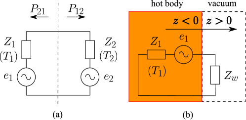
For example, in a geometry where a body occupying halfspace emits into empty halfspace [Fig. 1(b)] one may conveniently expand the radiated field over the set of free-space plane waves (both propagating and evanescent) with arbitrary transverse wave vectors . Such modes split into transverse electric (TE) (or -polarized) waves and transverse magnetic (TM) (or -polarized) waves. The wave impedances of these modes (where ) satisfy
| (2) |
where is the free-space wavenumber, and is the free-space impedance. Respectively, in the equivalent circuit of Fig. 1(b), .
The impedance in this case coincides with the input impedance of the halfspace for a given plane wave incident from the halfspace . This impedance can be expressed through the corresponding complex reflection coefficients as
| (3) |
By applying the fluctuation-dissipation theorem [21] (FDT) to the circuit of Fig. 1(a) one finds the mean-square spectral density of the fluctuating EMF as follows (in this article we use rms complex amplitudes for the time-harmonic quantities defined by , where ; therefore, ):
| (4) |
where is Planck’s mean oscillator energy (here, ), is Boltzmann’s constant, and is the absolute temperature of the emitter (when ) or the surrounding space (when ). Actually, Eq. (4) is nothing more than Nyquist’s formula for the thermal noise in electric circuits [22] where electrical engineers usually approximate . Let us note that relation (4) implies that the bodies that exchange radiative heat are kept in thermodynamically equilibrium states, which, strictly speaking, is possible only either when or under the assumption that the internal thermal energy stored in the bodies is infinite.
The thermal radiation power within a narrow range of frequencies delivered from the side of the emitter, , to the side of the environment, , is expressed in our formulation (per each spatial harmonic) simply as
| (5) |
In Ref. [20] it is proven that such a circuit model approach based on modal decomposition of the thermal fluctuating field is fully equivalent to the more complicated theories operating with distributed fluctuating currents. However, in contrast to these classical methods, our approach allows us to reduce a heat transfer maximization problem to the well-known circuit theory problem of matching a generator with its load.
4 Maximization of emitted power: complex-conjugate matching versus usual impedance matching
Having at hand an equivalent circuit representation described above, we may now ask ourselves under which conditions the spectral density of power radiated by a hot body is maximized? Due to the orthogonality property of the spatial harmonics used in the field expansion, in order to maximize the total emission we need to maximize the power delivered by each harmonic separately. As is clearly seen from Eq. (5), for the modes with a non-vanishing real part of the wave impedance: , the delivered power is maximized under the complex-conjugate matching condition: . Under this condition, the maximal possible emitted power per a spatial harmonic per unit of frequency is, from Eq. (5),
| (6) |
Note that for the spatial harmonics characterized with complex wave impedance, the conjugate matching condition is, in general, different from the zero reflection condition in the equivalent circuit of Fig. 1(a), which implies the usual impedance matching . Thus, by minimizing reflections for the waves crossing the boundary between the emitter and the surrounding space, one does not necessarily maximize the emission! Indeed, the power spectral density under the usual impedance matching condition (in what follows we call it simply “impedance matching”) attains [Eq. (5)]
| (7) |
Recall that is related to the wave impedance of the surrounding space. Therefore, as soon as this environment is characterized with complex impedance (for example, when the surrounding space is filled by a dielectric with loss), an impedance-matched, non-reflecting body — that is the black body in its conventional and intuitive definition — will not anymore be the one that attains the maximal spectral emissivity.
Let us also mention one important case when the impedance matching condition is sufficient to maximize the power emitted from a body to free space. It is the case when the emitting body is so large that it can be modeled with the geometry of Fig. 1(b). As was mentioned in Sec. 3, in this case the basis of orthogonal spatial harmonics is composed of propagating and evanescent plane waves. The wave impedances of these modes are given by Eq. (2). The evanescent plane waves with have and, thus, in accordance with Eq. (7), do not contribute into the far-field emission at all. The propagating modes with have and . Because the wave impedance of these modes is purely real, the maximum emission condition for these waves coincides with the condition . Therefore, the optimal emitter in this case is the half-space with zero reflection: , i.e., the black half-space. This essentially forbids any far-field super-Planckian emission in such geometries. However, it does not follow from here that the same conclusion must hold in geometries involving objects of finite size.
5 Free space far-field thermal emission from bodies of finite size
Let us now focus on geometries involving optically large spherical emitters in free space, or, more generally, any finite size emitters which completely fit into a sphere of a fixed radius . An analogous treatment can be applied to cylindrical emitters.
It is well-known that the electromagnetic field produced by the sources that are fully contained within a finite volume can be expanded (in the space outside this volume) over the complete set of vectorial spherical waves, defined with respect to a spherical coordinate system whose origin lies within this volume. These modes split into TE waves (with ) and TM waves (with ), with the field vectors expressed through a pair of scalar potentials , where are Laplace’s spherical harmonics, and with being the spherical Hankel function of the first kind and order . The function is also known as the Riccati-Hankel function of the first kind. The transverse electric field and the transverse magnetic field in these modes are related as (see A), where is the wave impedance of the spherical wave harmonic with the polar index () and the azimuthal index (), which can be expressed as
| (8) |
Note that the wave impedance of a mode depends on the radial distance and the polar index , and it is independent of the azimuthal index . We exclude the purely longitudinal mode with because it does not contribute into the radiated power.
Wave impedances of spatial harmonics (8) correspond to spherical waves emitted from an object comprising the point . For incoming spherical waves (see, e.g., Ref. [23]), the wave impedances are expressed through the Riccati-Hankel functions of the second kind , , and are equal to the complex conjugate of the impedances given by Eq. (8). Such waves are also called anti-causal waves, because they cannot be created just by remote external sources: A presence of a scatterer (which is sometimes called “sink”, as opposed to “source” [23]) in the vicinity of point is necessary for them to appear. Nevertheless, it is convenient to use such waves to describe the heat transfer from the remote environment to the body surface (we will use such waves in Sec. 6 and 7).
The striking difference in the properties of the spherical wave harmonics as compared to the plane wave harmonics discussed in the last paragraph of Sec. 4, is that the wave impedance (8) has a non-vanishing real part for the harmonics with arbitrary high indices and . Therefore, there are no fully evanescent waves among the spherical wave harmonics: Each mode, whatever high index it has, contributes into the far field. Hence, based on the results of Sec. 4, we may conclude that at any given wavelength there is a possibility to satisfy conjugate matching condition for the entire spectrum of spherical waves that are emitted by a body with a finite radius. In this case, a special emitter must be crafted which will provide the input impedance for all the modes with arbitrary indices and . We postpone the discussion of this realization until Sec. 8.
Under such perfect conjugate matching condition, the total power (per unit of frequency) emitted by the body at a given wavelength (with both TE and TM polarizations taken into account) satisfy
| (9) |
i.e., it grows infinitely. Thus, at least from a purely theoretical point of view, there is no upper limit on the power spectral density of the far-zone thermal radiation produced by a body of a constrained radius at a given wavelength. Note that in this consideration we did not make any assumptions regarding the radius-to-wavelength ratio or the internal structure of the body.
In order to understand this result, let us compare the perfect conjugate-matched case of Eq. (9) with the case when the emitter is simply impedance matched, which is expressed in our equivalent circuit model by the condition . Under this condition, the power spectral density per a single spherical harmonic can be expressed from Eq. (7), which leads to
| (10) |
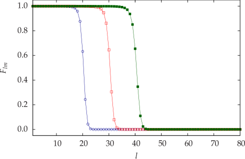
where the index labels the polarization. The factor on the right-hand side of Eq. (10) is close to unity for and decreases to zero very rapidly when . This is illustrated in Fig. 2. The reason for this is that in the spherical waves with the electromagnetic energy in the vicinity of emitter’s surface is mostly concentrated in the near fields (reactive fields) which decay faster than with distance and, thus, do not contribute into the far field. Respectively, the wave impedance of these waves is such that , which results in the emissivity cut-off at about . The same cut-off can be explained also by the fact that on the surface , a spherical wave harmonic with an index forms a wave pattern with the characteristic spatial period . Therefore, when , this period is less than the wavelength so that the mentioned mode behaves at the surface similarly to an evanescent plane wave. Note that such a cut-off is not present under the conjugate matching condition , because in this case the reactive components in and have opposite signs and compensate one another, i.e., the conjugate matching condition is essentially a resonant condition in the equivalent circuit of Fig. 1(a).
Therefore, when dealing with an impedance matched emitter, we may approximate by unity when , and by zero when when . This excludes the modes with from summation (10), and we obtain the following closed-form expression for the power spectral density:
| (11) |
From this formula, by substituting and taking into account that , we get
| (12) |
Recognizing as the area of the spherical surface, we obtain from Eq. (12)
| (13) |
which coincides with the amount of power (per unit frequency and unit area) emitted by a black body sphere kept under temperature : , where is Planck’s black body spectral radiance.
Thus, an optically large impedance matched body is equivalent in its emissive properties to Planck’s black body. This is expected, because such a body is typically understood as made of a black, non-reflecting material with impedance matched to the free-space impedance at arbitrary angles of incidence. Black bodies of finite size modeled as apertures in walls of large opaque cavities also behave similarly, due to the full match between the domains inside and outside the cavity.
It is instructive to relate the number of independent spherical harmonics into which a hot body can emit with the number of photonic states in free space. Let a spherical body with radius be situated in vacuum, and consider a free space gap with thickness (an empty spherical layer) adjacent to it such that . Then, the number of photonic states within this gap which transfer energy away from the body is
| (14) |
where is the photonic density of states in vacuum.
The same quantity can be also expressed by counting independent spherical waves within the same gap:
| (15) |
where is the maximal spherical harmonic index up to which the body emits efficiently, and is the one-dimensional photonic density of states.
By comparing Eqs. (14) and (15) we find that , i.e., the same limit as for a black body. However, note that, by definition, the photonic density of states in vacuum accounts only for the states which correspond to propagating waves, i.e., to real photons. Evanescent waves — which correspond to virtual, tunneling photons — are not accounted in such description. Respectively, emission above the black body limit is possible only by such tunneling. For instance, radiating in a mode with index , where , must involve photon tunneling from the body surface at to the distant surface , where there is an available photonic state for it. Due to this process, the radiative heat flux will be super-Planckian in the range of radial distances . At distances greater than , the radiation flux will remain sub-Planckian in the sense that its spectral density does not exceed the one produced by Kirchhoff-Planck’s black body with radius .
Thus, the conjugate-matched body can emit significantly higher power per unit of area and per unit of frequency as compared to Planck’s black body of the same size only because the conjugate matching condition tunes the emitter at resonance with high-order modes, due to which these modes are excited with a very high amplitude. Although these modes are essentially dark modes (because they are very weakly coupled to free space), the resonance greatly increases probability of photon tunneling from one of such states at emitter’s surface to a propagating free space state at some large enough radial distance. Obviously, such a resonant photon tunneling effect is not possible with a body made of a simple absorbing material.
Finally, let us note that the conjugate matching condition at an emitting spherical surface mathematically coincides with the zero-reflectance condition for the anti-causal spherical waves incident on the same surface (see Sec. 6 for more detail). In such picture, the conjugate-matched emitter stands out as a perfect sink for these waves. The energy transferred by such waves is totally absorbed at emitter’s surface without any reflections. Thus, for finite size emitters, one might try to amend the definition of the ideal black body in such a manner that it would refer to the conjugate-matched emitter rather than to the impedance matched one. One, however, would have to accept in this case that such a redefined ideal black body is characterized by infinite effective absorption cross section independently of its real, physical size. This point is discussed with more detail in the next section.
6 Scattering, absorption, and extinction cross sections of finite size bodies under conjugate matching condition
The scattering, absorption, and extinction cross sections at a given frequency are, by definition,
| (16) |
where is the power flow density in an incident plane wave with the given frequency, and , , and are, respectively, the amounts of power scattered by the body, absorbed within it, and extracted by it from the incident field. Without any loss in generality, we may assume that the incident wave is propagating along the -axis, and is linearly polarized: .
As is well known, an incident plane wave can be expanded into vectorial spherical waves. The notations for such waves vary a lot in literature, but when reduced down to Riccati-Bessel functions and derivatives of the Laplace spherical harmonics the expansion can be written as follows (only the electric field component transverse to is of our interest):
| (17) | |||||
were is the Riccati-Bessel function of the first kind with being the spherical Bessel function of the first kind and order , and . In the inner summation over the index acquires just two values: and . The first term in the square brackets of Eq. (17) proportional to is due to the TE-polarized spherical waves and the second one proportional to the derivative of the same function is due to the TM-polarized part of the spectrum. These two contributions are mutually orthogonal.
Note that the Riccati-Bessel functions in expansion (17) are simple superpositions of the Riccati-Hankel functions and (of course, the same refers to their derivatives):
| (18) |
Therefore, in the plane wave expansion (17) there are two types of spherical waves — leaving waves propagating towards and incoming ones propagating towards , having exactly the same magnitudes. Thus, the incident wave expansion (17) is essentially an expansion over standing spherical waves. This is not surprising, as the net power flow through any closed surface (with no enclosed scatterers!) vanishes for any plane wave. This explains our earlier remarks regarding the anti-causality of incoming waves. So, these waves may not be excited exclusively by remote sources alone. Even though such waves seem to arrive from , they may be separated from their causal pair only due to scattering on an object located in the vicinity of the point . The scattering destroys the perfect balance between leaving and incoming waves which exists in the incident field.
Hence, the expansion (17) can be seen as composed of the counter-propagating TE- and TM-polarized spherical waves with indices and , and with complex amplitudes
| (19) |
where we use letter to denote waves propagating towards , and letter for the oppositely propagating ones. In these notations,
| (20) | |||||
An object located in the vicinity of the point perturbs the balance of the incoming and the outgoing spherical waves, resulting in nonvanishing and , and . The closed-form expressions for these quantities are derived in B. Although similar derivations can be found in many sources on optical scattering, in B we use our original impedance-based formalism, which allows us to relate the scattering theory results to the results of our equivalent circuit model in the most natural manner.
The normalized scattering cross section is obtained based on the results of B and reads
| (21) |
where the reflection coefficients are given by Eq. (56).
For an ideally conjugate-matched body, [here, has absolutely the same meaning as in the equivalent circuit of Fig. 1(a)], therefore, as it follows from Eqs. (56) and (52), . Hence, in this case
| (22) |
Note that our derivation remains valid when , thus, we may conclude that even for optically large bodies, the scattering cross section is not limited by the geometric cross section and can be arbitrary high. Moreover, because the total power associated with an incident plane wave is infinite, the power scattered by an object can also be arbitrary high.
Our model allows us to conclude also that an optically large body with radius made of an absorbing material with characteristic impedance close to that of free space will behave similarly to the impedance matched body considered in Sec. 5. Namely, for such a body, for modes with , , and for the modes with . Respectively, the normalized scattering cross section of such a body is
| (23) |
i.e., its scattering cross section coincides with the geometric cross section.
The absorption cross section is derived in B and satisfies
| (24) | |||||
Note the apparent similarity of the terms under summation (24) with Eq. (5). From Eq. (24) one can see that because a perfectly conjugate- matched body is characterized with , the absorption cross section of it is infinite, similarly to the scattering cross section we have found earlier. It is also directly seen that the conjugate matching condition maximizes the summation terms in Eq. (24). Analogously to what have been done earlier, one may verify that the absorption cross section of a large impedance matched body is . Finally, the extinction cross section of an arbitrary body can be found from Eq. (21) and (24) as .
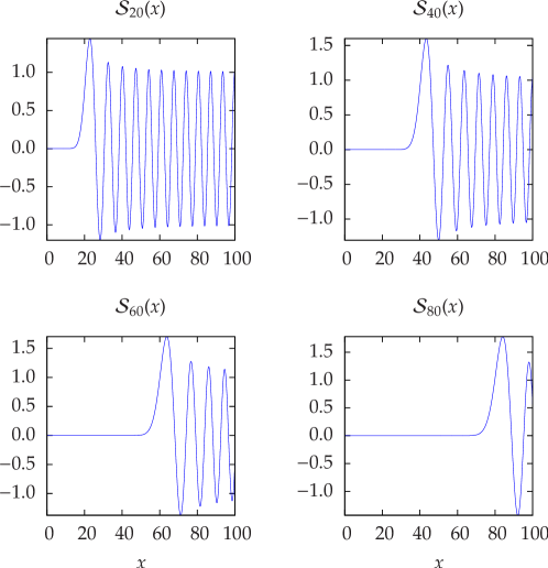
To conclude with the study of this section let us try to analyze (now from the point of view of scattering theory) what property makes it possible to achieve the values of the normalized absorption cross sections much greater than unity, which, reciprocally, increases in the same proportion the effective spectral emissivity of a body. In order to do this, let us consider the behavior of the incident field expansion (17) within the spherical domain . Although all terms in expansion (17) produce a non-vanishing contribution within this region, the dominant contribution is due to the modes with polar indices such that . Mathematically, this can be seen from the asymptotic behavior of Riccati-Bessel functions at small values of argument: (here, is the Gamma-function; this asymptotic is valid up to ), therefore, the modes with quickly decay in this region when approaches zero. Fig. 3 shows the radial behavior of a few spherical standing waves in the vicinity of this region.
This demonstrates that when an object such as, for example, a ball made of some absorbing material is placed in the region it will mostly interact with the modes with the indices . Thus, the power transport from the remote environment to this object will be mediated by these modes dominantly. Reciprocally, when the object is the source of thermal radiation, the fluctuating currents in the object will excite the same set of modes, so that only the modes with will participate in the reversely directed heat transport. However, it is not hard to imagine that a specially crafted body can be forced to interact also with the higher order modes with , because, besides being weak, these modes nevertheless penetrate into the region . The strongest interaction is achieved at the resonant condition , which maximizes the terms of summation (24). Thus, the physical reason for the increased interaction is this resonance.
7 Implications with regard to second law of thermodynamics and Kirchhoff’s law of thermal radiation
One may think that the result of Sec. 5 — which essentially states that a body of an optically large but finite size may emit, theoretically, arbitrarily high power per unit of frequency and per unit of area — contradicts the second law of thermodynamics. For instance, earlier claims of super-Planckian thermal radiation from photonic crystals were rebutted in Ref. [11] on this ground (we discuss this reference in more detail later in this section). This is, however, not our case. From the equivalent circuit of Fig. 1(a) it is immediately understood that the conjugate matching condition that maximizes the radiated power, at the same time maximizes the power delivered from the environment back to the emitting body, i.e., the optimal heat emitter is at the same time the optimal heat sink! The same conclusion can be drawn from the results Sec. 6, in which we have demonstrated that the absorption cross section of a body is maximized under the same conjugate matching condition. Therefore, the conjugate matching condition preserves the balance of radiative heat exchange between the body and its environment when . The symmetry of the equivalent circuit (a consequence of the reciprocity principle), actually, simply forbids obtaining from our theory any result that would violate such thermodynamical heat exchange balance. On the other hand, from the same circuit it immediately follows that when the net radiative heat flow is always directed from the side with higher temperature to the side with lower temperature.
In order to study implications of our theory with regard to Kirchhoff’s law let us inspect how large is the power associated with an incoming spherical wave incident from the the side of the remote environment (kept at temperature ), in a general scenario when the input impedance of the body . The environment — free space in our case — is characterized by impedance .
The expression for the power received by the body from the environment is readily obtained from the equivalent circuit model:
| (25) |
This power can be split into the incident and reflected power: , where
| (26) |
In this formula, is the wave impedance for the spherical wave propagating from towards , and is the power reflection coefficient of this wave at the body surface. Thus, by combining Eqs. (25) and (26), we obtain
| (27) |
The above result shows that in a free space environment filled with thermal-fluctuating electromagnetic field characterized with temperature every spherical harmonic propagating towards the point delivers the same amount of heat power: . Thus, the amount of power transported by all such harmonics with arbitrary indices and to an object comprising the point is infinite. Kirchhoff-Planck’s black bodies and ordinary absorbers reflect most of this incident power: Only the power delivered by the incident modes with (see Sec. 6) can be efficiently received by such bodies. Reciprocally, they radiate back only into the same limited number of outgoing modes. On the contrary, an ideal conjugate-matched body is theoretically able to receive the whole infinite power delivered by all such incident waves, as well as to radiate it back.
Comparing Eq. (27) with Eq. (5) when we may write
| (28) |
where . Eq. (28) is a generalization of Kirchhoff’s law of thermal radiation. Indeed, the dimensionless parameter has the meaning of absorptivity of the body for a given spatial harmonic; is the emitted power at the same spectral component; and the ratio of these two quantities is a universal function of just frequency and temperature. Note that unlike the classical law of the same name, Eq. (28) is written for a single component of the spatial spectrum of the radiated field. Thus, Eq. (28) complements the principle of detailed balance by making it applicable to separate spatial harmonics of the radiated field.
Thus the classical Kirchhoff law of thermal radiation, which states that: “For a body of any arbitrary material, emitting and absorbing thermal electromagnetic radiation at every wavelength in thermodynamic equilibrium, the ratio of its emissive power to its dimensionless coefficient of absorption is equal to a universal function only of radiative wavelength and temperature — the perfect black body emissive power,” will hold for any emitter — being optically small or large, including the ones characterized with much greater than their geometric cross section, — if we disregard the intuitive definition of the perfect black body as an “ultimate absorber” which attains the absolute maximum in absorptivity (as compared to all other bodies), in favor of defining the ideal black body just as an abstract object characterized with the emissive power (28). Indeed, a conjugate-matched body receives from the environment and absorbs a much greater power than the conventional black body of the same size, so that its effective absorptivity relative to the black body is much greater than unity: (see Sec. 6).
Finally, let us consider a thought experiment described in Ref. [11], where a presumably super-Planckian thermal radiator exchanges thermal energy with an ideal black body located in far zone. If both objects are infinite in spatial extent (two parallel infinite slabs), super-Planckian far-field radiation is impossible, as we have proven in Sec. 4, and there is no need for thermodynamic considerations to prove that again. On the other hand, when a pair of finite-size bodies are separated by a distance significantly greater than the heat exchange flux is also sub-Planckian.
Next, by considering the case of two finite-size bodies separated by a distance smaller than but still much greater than the wavelength, we note that consideration from Ref. [11] would assume in this case that the black body perfectly absorbs all incident power, while its radiation is, naturally, restricted by the Planck law of black body radiation. This assumption, obviously, implies a violation of the second law of thermodynamics, because it violates the reciprocity of the heat exchange.
However, as we have shown above, Kirchhoff-Planck’s black body perfectly absorbs only the fully propagating part (ray part) of the incident spatial spectrum. The higher-order spherical harmonics incident on the black body surface which are responsible for the super-Planckian part of the radiative heat, will be reflected from its surface, and only the ray part will be ideally absorbed and re-emitted by the receiver. The reflected super-Planckian part of the radiation will be scattered into the surrounding space. Part of this energy will then be re-absorbed by the conjugate-matched emitter, which acts as the ideal sink for all incident waves.
Obviously, when the two bodies have the same temperature, there is no net heat flow between them, and, thus, the second law of thermodynamics is not violated. One can say that the Nature avoids such violation by totally reflecting the photons which cannot be re-emitted by the receiving body. On the other hand, there is no limitation for emission of those photons into free space from a conjugate-matched emitter which interacts resonantly with the entire infinite spectrum of outgoing spherical waves. Such emission is possible because for such ideal emitters all photonic states in the surrounding empty space are available, by the process of resonant photon tunneling discussed in Sec. 5.
It is instructive to note here that in the above scenario it is still possible to realize a super-Planckian heat exchange between an ordinary body (i.e., a real body with loss, as opposed to the ideal Kirchhoff-Planck’s black body discussed above) and a specially crafted body which is conjugate matched to the modified environment which takes into account the presence of the first body, i.e., in this case the conjugate-matched emitter must be designed so that it maximizes the probability of photon tunneling between the two bodies. Because the tunneling process is reciprocal, the second law of thermodynamics is not violated although the ordinary body will emit above Planck’s limit in this scenario.
8 Conjugate-matched DNG sphere: metamaterial “thermal black hole”
Let us now discuss the practical implications of our theoretical findings. It is clear that realizing conjugate matching condition for waves with polar index in a practical thermal emitter is impossible in emitters formed by homogeneous dielectrics or magnetics with positive constitutive parameters. For such materials, the standard arguments of Ref. [4] apply.
Hence, here we shall investigate if a magneto-dielectric sphere filled by a material with less restricted parameters and (e.g., a metamaterial) can be used in realization of the conjugate-matched emitter. It is known that the complex permittivity and permeability of a passive material at a given frequency can have either positive or negative real parts, while the sign of the imaginary part is fixed: . Because our goal is to realize an omnidirectional emitter, the material parameters and may depend on , but should not depend on the angles and . Thus, we are ought to find such and that will make the input impedance of a sphere made of this material to become equal to the complex conjugate of impedance (8) for spherical harmonics with arbitrary indices.
In order to do that we first solve an auxiliary problem: With which uniform material should we fill the domain , so that the input impedance of this domain becomes the complex conjugate of (8)? The answer to such a question can be obtained from Eq. (8) generalized for the case when , which reads
| (29) | |||||
| (30) |
Consider the properties of the radial function and its derivative:
| (31) |
which hold when . When and are such that , with loss tangent , the refractive index becomes , and we obtain from (29)–(31) for the input impedance of the domain filled with such material:
| (32) |
which is exactly the complex conjugate of the wave impedance (8).
However, we need to obtain such result not for the input impedance of the domain , but for the input impedance of the domain occupied by the emitter. Hence, we need to amend the above consideration somehow so that it applies to the domain . This can be achieved by applying a proper coordinate transformation to the Maxwell equations. Such transformation should map the domain into the domain while preserving the field equations in their usual form. The latter ensures that after such transformation the input impedance of the transformed domain coincides with the one for the original domain: .
The transformation with the required properties is derived in C. Indeed, under this transformation, and . Because , where , the nabla operator transforms as . This effectively transforms the material parameters of a uniform magnetodielectric to and , while preserving the usual form of the Maxwell equations (see C for more detail).
Therefore, a spherical emitter with radius made of a DNG metamaterial with parameters
| (33) | |||||
| (34) |
will have the input impedance coincident with Eq. (32) when . Note that this impedance approaches arbitrarily closely when , for modes with arbitrary indices. Thus, an emitter filled by a material with parameters (33) and (34) constitutes a physical realization of the conjugate-matched emitter introduced in Sec. 5.
A similar profile of was used in the theoretical [24] and experimental [25, 26] papers where all the materials have positive real parts of the permittivity and permeability. This leads to a spherical object which theoretically fully absorbs all rays incident on its surface, that is, behaves as a Kirchhoff black body. In contrast to our proposed body whose absorption cross section is theoretically infinite, the absorption cross section of the “optical black holes” described in Refs. [24, 25, 26] equals to the geometric cross section of the body. A quasistatic case in which a cylindrical body appears having a larger radius than its physical radius was considered in Ref. [27].
Following the same terminology, we may designate a body characterized with the parameters (33)–(34) as a metamaterial “black hole”. With this, we emphasize the property of this object to intercept rays of light which are not incident directly on its surface. Due to this feature, such an object has an effective radius of ray capture (kind of “Schwartzschild radius”) which can be much greater than the geometrical radius of the body. The latter, in the case of the ideal conjugate-matched body, can have arbitrarily small dimensions, much like the mass singularity in a black hole in Einstein’s gravitation theory. Indeed, as it has been found in Sec. 6 an ideal conjugate-matched object has infinite absorption cross section, independently of its geometric size. Hence, in a geometric optics approximation any incident ray will end up hitting such object.
Note however that due to the inevitable dispersion of the DNG medium, our metamaterial black hole is not “black” in the usual optical sense, as its absorption is frequency dependent. Our black hole is also different from its astrophysical counterpart in that sense that when we heat it up it emits light (actually, real black holes emit radiation and particles as well, but let us not go too far with such analogies). Because of this, and also because such an object behaves as an ideal radiative heat sink we may also attach a label “thermal” to its name.
Although, theoretically, can be arbitrary small while still allowing for a non-vanishing loss within the emitter (which is the necessary condition for thermal emission to occur), in practice, is always finite. Moreover, close to the core of the emitter the parameters (33) and (34) are divergent: , when . These factors limit the number of spherical harmonics of the radiated field for which the conjugate matching condition can be fulfilled in practice. Therefore, the situation represented by Eq. (9) can never be achieved in an experiment. One, however, can still expect a significant increase in the emitted power for emitters with parameters resembling those of Eqs. (33) and (34), especially, for emitters characterized with moderate values of the ratio . For such emitters we can have , while still . We may still designate these more realistic objects as “black holes” in our fancy way of giving names, however, the effective Schwarzschild radius of these holes will be finite, like for black holes of any finite mass in astrophysics. Respectively, the astrophysical counterpart of the ideal conjugate-matched emitter is a black hole of an infinite mass.
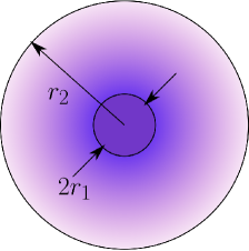
Let us study the case in more detail and obtain an expression for the effective absorption cross section of a core-shell metamaterial emitter with parameters and that follow Eqs. (33) and (34) within a spherical shell , and with uniform parameters , within the core (see Fig. 4). The loss tangent of the DNG metamaterial is assumed to be finite, but small: . Note that there is also another possibility of realizing the necessary level of absorption in the metamaterial black hole: we may choose within the region , and concentrate all the loss in the core region with a high value of .
Let us denote the input impedance of emitter’s core for a given spherical harmonic by . This impedance can be calculated as
| (35) | |||||
| (36) |
These relations are analogous to the expressions for the impedance of the incoming spherical waves, with the radial dependence function replaced by . Next, the input impedance of the whole emitter can be expressed as
| (37) |
where , , and , , are the equivalent -matrix parameters of the spherical shell for the same spherical harmonic. By using the equivalence between the shell region and the domain under the transformation , these parameters can be calculated from known formulas for -parameters of uniformly filled spherical shells (see A).
The absorption cross section can now be calculated with the help of Eq. (24). It can be easily checked that for a body with (which is our case), . Also, due to emitter’s symmetry these reflection coefficients are independent of the azimuthal index . Therefore, from Eq. (24) we obtain the following expression for the absorption cross section:
| (38) |
in which the impedances need to be calculated just for a single polarization (it does not matter for which). The numerical results obtained with the help of Eq. (38) are presented in the next section.
9 Numerical results
We consider the core-shell emitter depicted in Fig. 4. The shell has the inner radius and the outer radius and is formed by a DNG metamaterial with parameters given by Eqs. (33) and (34). The core material has the parameters and . As shown in Sec. 8, the normalized absorption cross section of such a body must grow without limit when and the ratio both tend to zero. In this section we study numerically how fast is this growth and also identify how large the absorption cross section can become under typical practical limitations.
For the following it is crucial to note that the limiting behavior of when and is governed by both these parameters together. Thus different limits can be achieved depending on the relation between these parameters. For instance, it is trivial to see that for any fixed ratio , , which is very far from the desired result! However, when is fixed and the ratio varies, our numerical analysis shows that the limiting behavior of changes drastically. For the core-shell emitter characterized with (which is optically a relatively large object with circumference of 30 wavelength) this situation is depicted in Fig. 5 (left).
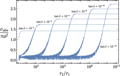
From this figure one can see that when the core radius decreases and the ratio increases, the body absorption cross section grows at first (with some oscillations related to the thickness resonances within the core-shell) and later stabilizes at a level determined by the fixed magnitude of the loss tangent. The tendency is such that at a smaller the achievable is higher, but the core radius value required for this becomes smaller and smaller when the loss tangent decreases.
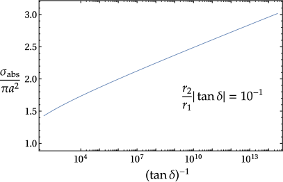
In this way, arbitrary high values of the normalized absorption cross section can be achieved provided and the core radius are decreased together. For instance, in Fig. 5 (right) we plot the dependence of on the inverse magnitude of under the condition that the product is kept constant. In this numerical case, when the parameter grows, the parameter increases in the same proportion, which results in a monotonic growth of the normalized absorption cross section.
However, results depicted in Fig. 5 show that growth of is very slow. Although the normalized absorption cross section can theoretically grow without limit provided suitably small values of the parameters and are chosen, in practice the range of varying these parameters is limited. For instance, considering operating at wavelengths on the order of 100 m, the parameter can probably at most reach , because higher values of this parameter would correspond to unrealistically small radii of the inner core (on the order of nm). As is seen from Fig. 5 (left) in order to maximize absorption in this case the loss tangent in the DNG shell must be decreased down to , which is impractical. On the other hand, attainable loss tangents values , keep the normalized absorption cross section below 2 (when ).
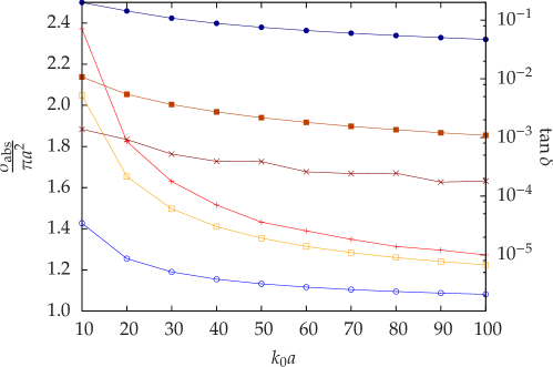
To study these limitations further, we consider the following two numerical examples. In the first example, we set , and, respectively, and vary within the shell such that . We calculate the normalized absorption cross section (38) for a set of values ranging from up to with a step . In this range, emitter’s circumference varies in the range from up to , which indicates that we deal with an optically large body. The values of the loss tangent are optimized at each value (using a numerical optimization procedure) in order to maximize the normalized absorption cross section at each point. The result of this calculation is presented in Fig. 6.
In the second numerical example we set (i.e., in this case the core is 10 times smaller) and repeat the same procedure (see Fig. 6). We observe that for in the first example with , the normalized absorption cross section , which means that at this point the DNG core-shell emitter is performing at least twice better than a black body emitter. Note that such a result is achieved at a loss level which is significantly less than in typical optical absorbing materials.
In the literature we could not find any example where the absorption cross section would be claimed exceeding the geometric one for such a large object. In work [9] targeted to maximization of the ratio of the absorption cross section to the scattering cross section it is stressed that the goal is achievable for optically small particles. Though the authors of Ref. [9] utilize a similar concept, they combine it with the plasmon resonance of a core-shell particle. Therefore, their particle with ought to be much smaller () than our DNG sphere.
Fig. 7 shows the power flux density (the Poynting vector) inside and outside the DNG core-shell object under plane wave incidence as defined in Sec. 6. Note that the power flux density in regions inside this object is much higher than in the outside region, which confirms that a metamaterial thermal black hole is able to greatly concentrate the incident power flux.
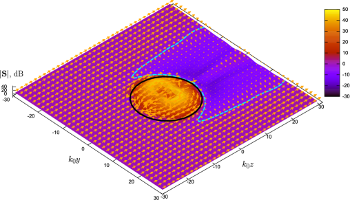
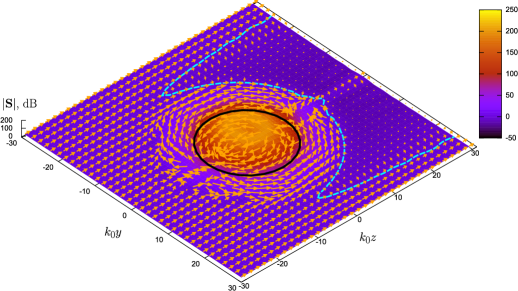
The behavior of the Poynting vector at the left and right sides of the body [i.e., close to the points ] is especially peculiar: The flux inside the object is directed oppositely to the incident flux, as if some power were received from the region of geometric shadow behind the object. Similar behavior was observed in DNG metamaterial waveguides and resonators [12]. One can also see from Fig. 7 that the shadow region has a larger diameter as compared to the diameter of the body which results in . The situation improves even more when the radius of the core is made smaller. The same figure also demonstrates the case with a very small value of the loss tangent in DNG shell region, when all the loss is concentrated within the core. In this case, a much more pronounced effect is obtained: the shadow size is about twice the size of the body.
In the second example of Fig. 6 with , the normalized absorption cross section attains when . Note, however, that in this case the range of parameter variation is already too large to remain practical: .
For reference, in Fig. 6 we also provide the result for the case of a uniformly filled sphere, which occurs when . For example, for , the uniform DNG sphere with loss tangent provides , i.e., even a uniformly filled sphere may outperform the black body of the same size by about 8% in this case.
In all examples, the optimum loss tangent value decreases with the increase of . The values of the normalized absorption cross section also decrease with . Nevertheless, even when , i.e., when emitter’s circumference is 100 wavelength long, we obtain more then 20% gain in emitter’s performance as compared to Kirchhoff-Planck’s black body of the same size (when ), and close to 30% gain when . The required loss tangent values in these two cases stay within reasonable limits, for instance, for the emitter with , which can be realized in an experiment. In our opinion, this is a remarkable result which shows that even for optically large bodies with there exist emitters which noticeably outperform Kirchhoff-Planck’s black body.
In general, with further decrease in the core radius and , the achievable values of become larger, however, they grow very slowly. Thus, we may conclude that approaching theoretical result in a practical DNG emitter will meet with unavoidable obstacles such as unrealistically high material parameters in the core region combined with very low levels of loss: .
10 Conclusion
In this paper we have proven, from the point of view of fluctuational electrodynamics which deals with bodies kept in thermodynamically equilibrium states and characterized with infinite internal thermal capacity, that there is no theoretical upper limit on the spectral power of thermal radiation of finite-size bodies. Thus, the fluctuational electrodynamics alone does not set up any bounds on the level of spectral power emitted by a hot body: for instance, a conjugate-matched emitter with radius can radiate a much larger (theoretically, infinitely larger) power at the wavelength than can be predicted for the same-size body by using Planck’s black body emission formula. This holds at any given wavelength, and even in a scenario when such a body radiates into unbounded free space.
This result was obtained by two independent methods: Firstly, by identifying the conditions which maximize the power emitted by a body when it performs as a source of thermal radiation, and, secondly, by maximizing the absorption cross section of a body. As expected, both derivations lead to the same conclusion stated in the previous paragraph. Moreover, we have proven that neither the second law of thermodynamics, nor Kirchhoff’s law of thermal radiation (when properly amended) are violated by theoretical existence of such strongly super-Planckian emitters.
We have proposed a physical realization of such conjugate-matched emitters, which employs low-loss media with simultaneously negative permittivity and permeability — DNG media. It is known that such media support strongly resonant surface excitations — surface plasmon-polaritons. In flat DNG slabs of infinite extent, these modes are bound to the surface and the energy associated with them cannot be emitted into free space. In other words, such modes may not participate in the far-zone thermal transfer in these geometries (on the other hand, these modes play the main role in the near-field super-Planckian thermal transfer). However, the same modes on a curved closed surface — like a spherical surface — always leak some energy to the free space modes. In our metamaterial superemitter such leakage is greatly enhanced by tuning the whole structure at resonance which maximizes the probability of free-space photon emission from such dark states. Thus, we show that a properly designed metamaterial structure may dramatically amplify the diffraction effects not considered in original Planck’s theory, and that these effects at a given frequency can be made even more significant than the standard, classical effects limited by the geometric optics approximation.
It is quite remarkable that, from a theoretical standpoint, a finite-size emitter with the double-negative material parameters derived in Sec. 8 performs as a thermal black hole whose absorption cross section grows without limit when the material parameters approach the ideal profiles given by Eqs. (33) and (34) with the loss parameter . Reciprocally, such idealized body has infinite effective spectral emissivity when compared to Planck’s black body of a similar size.
However, realizing such a truly super-Planckian emitter in practice meets with unavoidable obstacles rooted in our inability to obtain DNG metamaterials with extremely low values of loss and extremely high absolute values of the permittivity and permeability concentrated in a tiny region of space. For emitters with practically attainable parameters, the gain in spectral power is not that high and decreases when radius-to-wavelength ratio increases. Our numerical examples show that a practical spherical double-negative core-shell emitter can outperform Planck’s black body (at a given wavelength) by more than 100% for emitters with circumference on the order of 10 wavelengths, and by about 20-30% for emitters with circumference on the order of 100 wavelengths. However, considering wide-spread beliefs that optically large bodies can never outperform a black body of the same size when radiating into free space, in our opinion, this still makes a remarkable achievement even in practical terms.
Finally, let us note that the integral power emitted at all wavelengths remains sub-Planckian for any body formed by passive and causal components. This limitation can be readily demonstrated with the known sum rules for optical scatterers, although this is out of the scope of this paper.
Appendix A Impedances of spherical waves
The transverse electric and magnetic field components in a spherical wave harmonic are given by the following expressions:
| (39) |
| (40) |
| (41) |
| (42) |
where , for the outgoing spherical waves propagating towards , and , for the incoming waves propagating towards .
Next, considering, for example, the outgoing TM waves and forming the ratios of and we find:
| (43) |
and
| (44) |
from here we get that the transverse fields in the outgoing waves are related as , where . Considering in the same manner the outgoing waves of TE polarization, we obtain .
By performing a similar derivation it is straightforward to find that in the TM-polarized incoming spherical waves the transverse fields are related as , where . Respectively, for the incoming waves of TE polarization we obtain .
Note that because , the wave impedances of the incoming and outgoing waves are related as .
Let us now derive the expressions for the reflection coefficients . In the following we suppress the polarization and modal indices for brevity.
Let us consider a spherical body characterized with the input admittance , which is under incidence of an incoming spherical wave with the wave admittance . The body reflects this wave with the complex electric field reflection coefficient . The reflected outgoing wave has the wave admittance .
In order to find we use the boundary condition on body’s surface: , where and are the total (i.e., incident plus reflected) transverse electric and magnetic fields: , . From this condition we obtain
| (45) |
Taking into account that , we find from Eq. (45) that [Eq. (52)].
The -parameters for a uniformly filled spherical shell with an arbitrary inner radius and and arbitrary outer radius can be found in a similar manner by considering partial spherical waves propagating within the shell in the two opposite directions, and expressing through these waves the total transverse electric and magnetic fields at the surfaces and . From these expressions one obtains the following -matrix relation between the electric and magnetic fields at the two sides of the shell:
| (46) |
where the four -parameters: , , , and , are functions of the polar index only (they do not depend on the azimuthal index ). Because in calculation of the normalized absorption cross section (38) it is enough to consider just a single polarization, below we provide the final formulas for the -parameters for TM polarization:
| (47) | |||||
| (48) | |||||
| (49) | |||||
| (50) |
In these formulas, and are the absolute permittivity and the permeability of shell’s material, respectively, . In order to use these formulas in Eq. (37), one has to set and .
Appendix B Derivation of and
Due to the presence of a body in the vicinity of the point , the waves (20) will scatter on it, producing in this way the scattered field:
| (51) |
The amplitudes of the scattered waves can be found through the complex reflection coefficient for the corresponding incident spherical harmonic (see A):
| (52) |
where we have introduced body’s input admittance for a given spherical harmonic and the wave admittance . Note a subtle difference from the more usual reflection formula — the presence of the complex conjugate operation, — which arises from the fact that impedances of the counter-propagating spherical waves are different and equal the complex conjugate of each other (see A).
Using Eq. (52), we may write for TE wave reflections happening at surface :
| (53) |
Respectively, for the TM waves reflecting at the same surface,
| (54) |
Because in the incident plane wave expansion [Eq. (20)] , we find from Eqs. (53) and (54) that
| (55) |
where
| (56) |
are the reflection coefficients with redefined phase such as if the reflection happened at the point (note that ).
The total scattered power is found by integrating the expression for over the closed spherical surface with infinite radius. In doing so, we use the orthogonality of the Laplace spherical harmonics, and the fact that
| (57) |
where . We also take into account that when . Thus, we obtain for the total scattered power
| (58) | |||||
From here, the normalized scattering cross section is found as given by Eq. (21).
The absorption cross section can be found by considering the balance of powers delivered to the body by the incoming waves and taken away by the outgoing waves. The power associated with each incoming spherical wave is proportional to and the power associated with the outgoing waves of the same index and polarization is proportional to . The difference of these two amounts represents the absorbed power. Therefore, the total power absorbed in the body at a given wavelength can be expressed as [compare with Eq. (58)]
| (59) | |||||
From here we obtain the resulting Eq. (24).
Appendix C Coordinate transformation
Let us consider Maxwell’s equations with isotropic and uniform material parameters and :
| (60) |
In spherical coordinates,
| (61) |
Under a mapping , where is a monotonic function of , the nabla operator transforms as
| (62) |
The unit vector can be expressed as
| (63) |
where is the unit vector in the direction of growth of . From here and Eq. (62),
| (64) |
The expression in the square brackets reduces to the nabla operator in the primed frame when the function is such that , which has two solutions for monotonic : , and , where is an arbitrary constant.
Only the second possibility is of interest for us. Equating we get and, respectively, . Note also that for this transformation , but , and . Thus, this transformation changes a right-handed coordinate system to a left-handed one. Therefore, the same physical field vectors when referred from the two coordinate frames are related as and . The extra flip in the sign of the magnetic field is due to the fact that is a pseudovector (axial vector) which must change sign under an improper coordinate transformation. Note that this sign change is required in order to maintain the form of the input impedance expression after the transformation:
| (65) |
where and are unit vectors coincident with the propagation direction of the incident wave.
By substituting the above relations into Maxwell’s equations (60) (note that the curls also flip signs under an improper transformation) we obtain
| (66) |
The transformation of the material parameters is apparent from these equations.
References
- [1] Kirchhoff G 1860 On the relation between the radiating and absorbing powers of different bodies for light and heat Philosophical Magazine, Series 4 20 1–21
- [2] Planck M 1914 The Theory of Heat Radiation, second edition translated by M. Masius (Philadelphia: P. Blakiston’s Son and Co.)
- [3] Yu Z, Sergeant N P, Skauli T, Zhang G, Wang H and Fan S 2013 Enhancing far-field thermal emission with thermal extraction Nature Comm. 4 1730
- [4] Bohren C F and Huffman D R 2007 Absorption and Scattering of Light by Small Particles (Weinheim: Wiley-VCH Verlag GmbH & Co. KGaA) p 129
- [5] Tretyakov S 2014 Maximizing absorption and scattering by dipole particles Plasmonics 9 935–944
- [6] Bobrovnitskii Yu I 2006 Impedance theory of sound absorption: The best absorber and the black body Acoustical Physics 52(6) 638–647 (Original Russian Text: 2006 Akusticheski Zhurnal 52(6) 742–752)
- [7] Kwon D-H and Pozar D M 2009 Optimal characteristics of an arbitrary receive antenna IEEE Trans. Antennas Propag. 57 3720
- [8] Ruan Z and Fan S 2010 Phys. Rev. Lett. 105 013901
- [9] Estakhri N M and Alù A 2014 Minimum-scattering superabsorbers Phys. Rev. B 89 121416(R)
- [10] Reiser A and Schächter L 2013 Geometric effects on blackbody radiation Phys. Rev. A 87 033801
- [11] Trupke T, Würfel P and Green M A 2004 Comment on “Three-dimensional photonic-crystal emitter for thermal photovoltaic power generation [Appl. Phys. Lett. 83, 380 (2003)]” it Appl. Phys. Lett. 84 1997
- [12] Engheta N and Ziolkowski R W 2006 Metamaterials: Physics and Engineering Explorations (NJ: Wiley-IEEE Press)
- [13] Schelkunoff S A 1943 A mathematical theory of linear arrays Bell Syst. Tech. J. 22 80–107
- [14] Zakhariev L N and Lemanski A A 1972 Scattering of waves by “black” bodies (Moscow: Sovetskoje Radio) pp 34–48 (in Russian)
- [15] Wernsman B et al. 2004 Greater than 20 fuel-to-electricity conversion efficiency of a thermo-photovoltaic radiator module system using reflective/emissive spectral control IEEE Trans. Electron. Dev. 51 512
- [16] Chester D, Bermel P, Joannopoulos J D, Soljacic M and Celanovic I 2013 Design and global optimization of high-efficiency solar thermal systems with tungsten cermets Opt. Express 19(S3) A245
- [17] De Zoysa M, Asano T, Mochizuki K, Oskooi A, Inoue T and Noda S 2012 Conversion of broadband to narrowband thermal emission through energy recycling Nat. Phot. 6 535
- [18] Simovski C, Maslovski S, Nefedov I, Kosulnikov S, Belov P and Tretyakov S 2015 Hyperlens makes thermal emission strongly super-Planckian Photonics and Nanostructures: Fundamentals and Applications 13 31
- [19] Luo C, Narayanaswamy A, Chen G and Joannopoulos J D 2004 Phys. Rev. Lett. 93 213905
- [20] Maslovski S I, Simovski C R and Tretyakov S A Equivalent circuit model of radiative heat transfer 2013 Phys. Rev. B 87 155124
- [21] Callen H B and Welton T A 1951 Irreversibility and generalized noise Phys. Rev. 83 34–40
- [22] Nyquist H 1928 Thermal Agitation of Electric Charge in Conductors Phys. Rev. 32 110
- [23] Nisbet A 1955 Hertzian electromagnetic potentials and associated gauge transformations Proc. Roy. Soc. London A231 250–263
- [24] Narimanov E E and Kildishev A V 2009 Optical black hole: Broadband omnidirectional light absorber Appl. Phys. Lett. 95 041106
- [25] Cheng Q, Cui T J, Jiang W X and Cai B G 2010 New J. Phys. 12 063006
- [26] Yang Y, Leng L Y, Wang N, Ma Y and Ong C K 2012 Electromagnetic field attractor made of gradient index metamaterials J. Opt. Soc. Am. A 29 473
- [27] Milton G W, Nicorovici N P, McPhedran R C, Cherednichenko K and Jacob Z 2008 Solutions in folded geometries, and associated cloaking due to anomalous resonance New J. Phys. 10 115021