Design of a Surface Trap for Freely Rotating Ion Ring Crystals
Abstract
We present a design of an r.f. trap using planar electrodes with the goal to trap on the order of 100 ions in a small ring structure of diameters ranging between 100 m and 200 m. In order to minimize the influence of trap electrode imperfections due to the fabrication, we aim at trapping the ions around 400 m above the trap electrodes. In view of experiments to create freely rotating crystals near the ground state, we numerically study factors breaking the rotational symmetry such as external stray electric fields, local charging of the trap electrodes, and fabrication imperfections. We conclude that these imperfections can be controlled sufficiently well under state-of-the-art experimental conditions to allow for freely rotating ion rings even at energies comparable to the ground state energy of the rotational degree-of-freedom.
I Introduction
The electronic and motional degrees-of-freedom of ions trapped with electromagnetic fields are extremely well decoupled from their environment. In addition, lasers and electromagnetic fields allow for excellent control of both degrees-of-freedom on the single quantum level Leibfried et al. (2003); Häffner et al. (2008). Both of those properties make ion crystals nearly perfect systems to study many-body physics in closed systems Friedenauer et al. (2008); Richerme et al. (2014); Jurcevic et al. (2014); Ramm et al. (2014). While most experiments are carried out with linear ion strings, a particularly interesting structure is a ring of trapped ions. Proposals include mini-accelerators Blümel and Smaldino (1999); Schätz et al. (2001), dynamics of KinksLanda et al. (2010), quantum emulation of ring molecules, and the acoustic analog of Hawking radiation Horstmann et al. (2010). Recently, also rings of trapped ions have been suggested to realize the concept of so-called time crystals Wilczek (2012); Li et al. (2012).
However, starting from experiments on how to implement rings of trapped ions by Schätz et. al. Waki et al. (1992); Schätz et al. (2001), it has become clear that imperfections and charging will make it very hard to implement such experiments. Thus, a few design improvements have been proposed Lammert et al. (2006); Austin et al. (2007); Madsen and Gorman (2010). Furthermore, the Sandia group has implemented a ring trap on surface trap technology Tabakov et al. (2012). Common to those designs and experiments is that the resulting ring potential has relatively large diameters, making it difficult to compensate for imperfections.
Inspired by Ref. Clark (2013), we study a novel design, deviating from the idea of bending a conventional linear trap into a ring. In addition, with a planar electrode design amenable to microfabrication, we seek to reduce inevitable imperfections from the geometry as well as local charging of trap electrodes. The main feature of our geometry is to trap the ion ring far away from the trapping electrodes as compared to the typical ion-ion distance and the ring diameter itself. Thus local imperfections from stray charges affect the rotational symmetry of the ion ring much less as if the ions were trapped close to the trap electrodes.
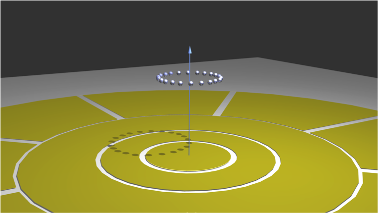
Our design is composed of concentric planar ring electrodes (see Fig. 1). Trapping is accomplished by applying suitable radio frequency (rf) voltage to those rings. Work by Clark suggest that the multipoles of such a trapping potential can be adjusted over a wide range by changing the rf voltage on the various rings Clark (2013). However, it is experimentally difficult to keep several rf high-voltage sources in phase. We thus design a trap requiring only one rf high-voltage source. Fixing this parameter, we aim to find a trap geometry yielding a rotationally symmetric potential minimum at the desired ring diameter and height.
For the study of the physics of symmetrization of the wavefunction of bosonic and fermionic ions discussed in the context of time crystalsWilczek (2012); Li et al. (2012), it will be important that the ion ring can freely rotate at the level of single rotational quanta. Keeping that in mind, we consider identical ions with mass and charge in a ring trap with diameter and a uniform magnetic field. The energy scales of its internal vibration modes are much larger than the energy scale of its collective rotation Burmeister and Maschke (2002). Thus, we focus on the collective rotation. Because of the required symmetrization of identical ions, the canonical angular momentum of the ion ring will be quantized according to for identical bosons, where is the quantum number of the rotation. The kinetic angular momentum is and the eigenenergy of the collective rotation is for identical bosonic ions, where is the normalized magnetic flux. This provides an energy scale of
| (1) |
For identical fermions, the energy scale is the same, although its dependence on can be different. For an ion ring of 100 40Ca+ ions with a diameter of 100 m, the energy scale of the collective rotation is nK. We seek to create a ring potential with sufficiently small imperfections such that a classical ion ring with rotational energy corresponding to the ground state energy would not be pinned by the imperfections.
In view of these considerations, it is important to trap the ion ring far away from trapping electrodes, while at the same time keeping the ion ring as compact as possible. Thus, heating is reduced while still maintaining a reasonable energy scale of the ground state. Additional design constraints are ease of symmetric trap fabrication as well as reasonable trapping voltages while maintaining an appreciable trap depth. To this end we target an ion ring with a diameter of 100 m trapped 400 m above the trap electrodes.
The remainder of the paper is organized as follows. In Sec. II, we briefly summarize the methods outlined in Ref. Clark (2013) on how to efficiently calculate rotationally symmetric potentials. Armed with the potential, we study the structure of ion crystals forming in such ring shaped potentials in Sec. III. We then analyze various imperfections breaking the rotational symmetry in Sec. IV, most notably external stray fields, electrode edge irregularities, and local charging of the trap electrodes. Sec. V addresses the process of cooling and pinning such a ring of ions.
II Calculation of the trapping potential
We start with the trap design proposed in Ref.Clark (2013) composed of planar ring electrodes of different radii and applied voltages. Given this cylindrically symmetric boundary condition, the analytic solution to Laplace’s equation is given by Kim et al. (2010)
| (2) |
where is the Bessel function of order. can be expressed as , and is given by
| (3) |
where and are the outer and inner radius of each ring electrode and is the amplitude of the rf voltage applied to the each electrode. In order to study ions in this oscillating trapping potential, we approximate the potential by the time-averaged pseudopotential
| (4) |
This approximation is valid when the oscillation frequency of the trapped ion is much smaller than the rf frequency.
Trap design
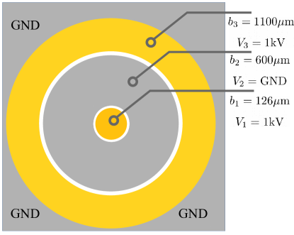
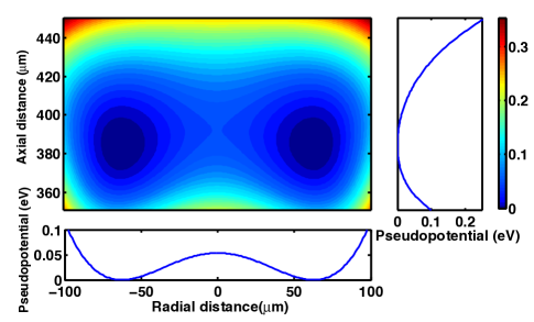
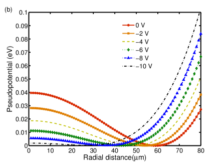
Ref.Clark (2013) showed that multipole surface traps can be built from concentric rings with particular sets of ring diameters and applied voltages. However, it is experimentally difficult to keep several rf high-voltage sources in phase. We thus design a trap targeting only one rf high-voltage source. Our design, shown in Fig. 2, is composed of three concentric ring electrodes with outer radius 126 m, 600 m, 1100 m, with the second ring grounded and the other two connected to a fixed rf driving source of amplitude = 1000 V. As the rf driving frequency, we choose MHz. In what follows, we also assume Calcium ions with mass amu. The design leads to a Mexican-hat-shaped pseudopotential in the radial direction and a confining pseudopotential in the axial direction, as shown in Fig. 3. The trap potential has minimum at radius m, height 385 m, and a trap depth of 0.134 eV, leading to single-ion trap frequencies MHz and MHz in the radial and vertical direction, respectively.
Design variation compensation
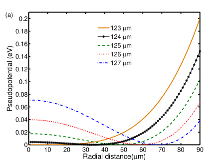
In view of fabrication imperfections, we study the effects of small deviation in the size of the center electrode. Our simulation Fig. 4 shows that the position of the potential minimum is very sensitive to the change in the size of the center electrode. In particular, it shows that changes of 1 m in radius will shift the radius of the minimum by 10 m. While we expect that microfabrication allows fabrication with tolerances below the micrometer range, we also can tune the potential by adding a small variable rf voltage with the same driving frequency on the second ring, but with the phase exactly opposite to that. Simulations show that the minimum position is shifted radially inward by about 2.5 m/V, while the trap depth changes by 0.005 eV/V. This small compensation rf voltage provides a powerful tool for fine-tuning the potential in situ.
III Structure of ring crystals
Of particular interest are the conditions under which ultra-cold ions form a ring in this potential. For this, we carry out molecular dynamics simulation to analyze the structure of laser-cooled ions in the surface trap Okada et al. (2007). We calculate the trajectories and velocities of the trapped ions by solving Newtonian equations of motion including the Coulomb interaction, the pseudoforce from the rf potential, and a hypothetical damping force term Meyrath and James (1998). The extra damping term serves as a friction term that will gradually reduce the energy of the ions, thereby simulating laser cooling. Thus, the ions will eventually reach a steady state, which represents the expected structure of the cold ion crystal. The equations of motion of the ion can be written
| (5) |
where is the damping coefficient, is the pseudoforce and the Coulomb force is given by
| (6) |
where is the number of ions in the trap.
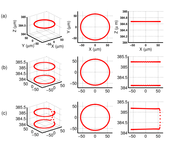
Subsequently, the equation of motion is numerically solved by fourth-order Runge-Kutta method with a time step of 20 ns. For a reasonable run-time of the algorithm of a few hours, we choose the damping coefficient kg/s. As a result, our simulation shows that a ring crystal can be formed with up to 92 ions with the parameters and geometry discussed above (outer radius of the inner electrode 126 m). As shown in Fig. 5(a), the 92-ion ring has diameter 116 m and height 385 m,
Keeping all parameters fixed, but adding one more ion yields a 93-ion ring crystal of two layers with about 1 micrometer separation in the plane perpendicular to the trap surface, as shown in Fig. 5(b). We can study this phase transition from single-layer ion rings to double-layer ion rings by fine-tuning the trapping potential. This can be done by adjusting the compensation rf voltage on the second ring, as we have discussed in Sec. II. In the double layer regime, we also find meta-stable kinks as shown in Fig. 5(c). The kink dynamics in a ring might be an interesting subject in its own right Landa et al. (2010). Contrary to studies in linear traps Mielenz et al. (2013); Ulm et al. (2013); Pyka et al. (2013), the kinks are in a homogeneous environment and cannot escape by just traveling to the edge of the ion crystal. Furthermore, working with an odd number of ions enforces the presence of an odd number of kinks and thus of at least one, while working with an even number of ions would lead to an even number of kinks.
IV Analysis of imperfections
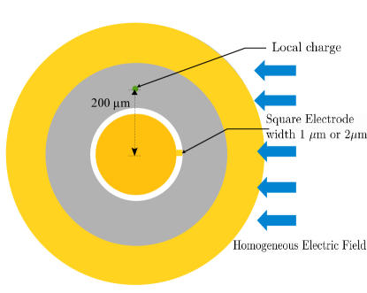
Of particular interest in our work is to create ion crystals freely rotating even if their rotational energy is comparable to the groundstate energy Li et al. (2012); Wilczek (2012). With with the criterion established in Eq. 1, i.e the energy barrier created by the imperfections should be be smaller than nK, we calculate the energy as a function of the angle when rotating the crystal around the symmetry axis. We study three sources of imperfections: a homogeneous electric field, irregularities on the edge of the electrodes, and the effect of a local charging (Fig. 6).
Homogeneous Electric Field
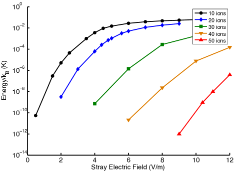
First we calculate the energy of the ion ring as a function of rotation angle in presence of an homogeneous electric field. The result will be a sinusoidal periodic function whose amplitude represents the classical energy barrier, which we denote (c.f. Fig. 8). Fig. 7 shows the energy barrier as a function of the applied field for 10, 20, 30, 40, and 50 ions. Fig. 7 illustrates that the energy barrier is drastically suppressed when the number of ions is increased. Recall that the energy gap is also proportional to the number of ions, . This suggests that freely rotating crystals with larger ion numbers are easier to observe, and suffer less from the imperfection of the trap. Intuitively, this can be understood in the following manner: for an increased ion number, the ion-ion spacing is much reduced approaching a more homogeneous and continuous charge distribution. For such an homogeneous charge distribution external imperfections cannot exert a torque on the charge distribution. Thus, the rotational barrier caused by the imperfection drastically reduces with an increasing number of ions.
Electrode Edge Irregularity
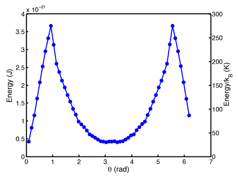
Next we add a square electrode of width 1 m (2 m) adjacent to the center electrode imitating a fabrication imperfection. The electric potential of a square electrode can be calculated from solving Laplace’s equation analytically Gotoh and Yagi (1971). We obtain the full potential by superposing this solution to the one obtained earlier. Fig 8 shows the energy of a 25-ion ring as a function of rotation angle with the square electrode of width 1 m and 2 m.
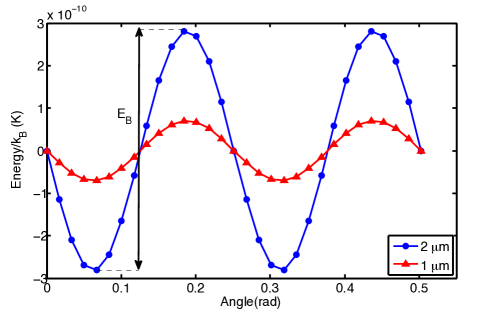
We concluded that already for 25 ions, the energy barrier is sufficiently small. Increasing the ion number reduces the ion-ion spacing which is expected to reduce the energy barrier further.
Local Charge
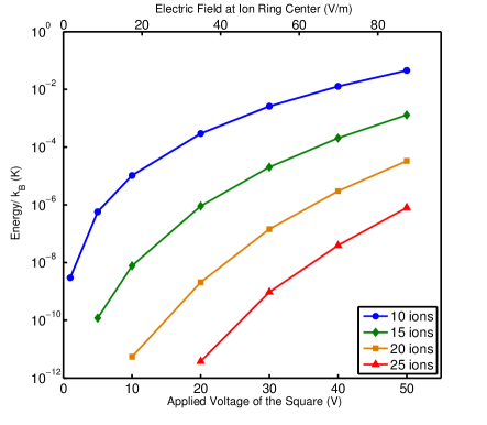
In surface traps with ion-electrode distances on the order of 100 m, we typically find electric fields on the order of 100 V/m before performing micromotion compensation. These fields come potentially from local charges on the trap surface as caused for instance by small charged dust particles on the electrodes. To study the effects of this, we assume that a square of size 10 m 10 m at a position 200 m from the center, which carries a different voltage than the rest of the electrodes. By applying 1V to 50 V DC to the square electrode, we create electric field of strengths from 2 V/m to 100 V/m at the center of the ion ring 385 m above the surface. The result is presented in Fig 9. We find that already a 25-ion crystal is nearly insensitive to charging of a 10 m 10 m surface to tens of volts. Again, increasing the ion number will reduce the energy barrier further, and thus allow for even stronger local charge imperfections.
V Laser Cooling
Finally, we study the laser cooling dynamics for freely rotating ion rings. In ion trapping experiments, usually a single cooling beam is preferred avoiding complications with interference effects. If this beam is centered perfectly on the ion ring, the radiation pressure will be balanced on each side of the nearly freely rotating ring. If, however, the beam is displaced from center, then a net torque from radiation pressure will result. Treating the ring as a rigid rotating body, we can apply the force equations for Doppler cooling Leibfried et al. (2003) and determine the net torque on the ring. In the limit of small velocities, at temperatures close to the Doppler cooling limit, we linearize the forces and the average torque on a single ion can be written as:
| (7) |
where is a radial vector of each ion. is averaged radiation pressure in the direction of laser beam propagation,
| (8) |
The drag coefficient for cooling,
| (9) |
is negative when the detuning is negative. The arises from the projection of the laser onto the rotational degree-of-freedom of each ion, , where is the velocity of the ion. The decay rate is given as ns) for Calcium, the wavenumber is defined as nm), and is the saturation parameter Leibfried et al. (2003). In what follows, we assume a saturation parameter of and a gaussian beam profile with a beam waist of 200 m. We chose a large beam waist to minimize the differences in intensity across the ring of ions and assume a detuning of MHz for optimal cooling.
The Doppler cooling action of the laser on the moving ions will counterbalance the torque from the radiation pressure. If the torque is sufficiently small, the forces will cancel at some finite frequency of rotation. For 30 ions confined to a m ring, we calculate the equilibrium frequency and find a rotation frequency of approximately 1.04 kHz per 1 m displacement of the cooling beam.
To counteract the rotation, we turn to the previous discussion of the effects of electric fields on the ring. By applying a strong electric field, we aim at creating a sufficiently strong energy barrier, thus stopping the ion ring from rotating. The maximum slope of the energy of the ion crystal as function of the rotation angle represents the torque needed to overcome the energy barrier and cause the ions to rotate around the ring
| (10) |
Aiming at a static ion crystal, the torque from the cooling laser on a single ion is . Next, we look to find an applied electric field that will cancel the torque from the laser for this displacement. This condition can be written as
| (11) |
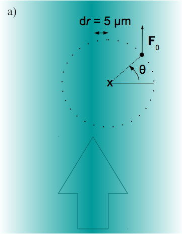
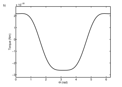
where represents the sum over the torque of all ions by a given electric field, with the field orientation chosen to maximize the torque, c.f. Fig. 10b).
For ion positions in the trap given an electric field of 75 V/m optimally aligned against the propagation of the laser, the total sum of the torque from the laser alone is approximately linear for small laser displacements d. Analyzing the situation for 30 ions and taking into account their calculated positions in the ion ring, we obtain N. The torque from the energy barrier for 75 V/m, given by the maximum slope of the curve in Figure 11, is Nm, allowing for a displacement d of up to 6.0 m to achieve a static ion crystal.
VI Conclusions
We have studied a design of a planar trap providing trapping of a 92 ion-ring of diameter 116 m at height 385 m above its surface. This design can be fabricated using micro-fabrication methods with high precision. We also studied the rotational motion under three symmetry-breaking imperfections: homogeneous electric fields, irregularities of electrode edges from fabrication imperfections, and local charges placed on the trap electrodes. We have shown that the rotational energy barrier induced by these imperfections drastically reduces with an increasing number of ions in the ring. We thereby expect that the energy barrier from the imperfections can be reduced below the rotational ground state energy of large ion crystals. In addition, we have shown that laser alignment and strong homogeneous electric field of 75 V/m can be utilized to pin and cool the ion ring for trapping and imaging.
Acknowledgements
This work is supported by the W.M. Keck Foundation. We acknowledge the contributions of Anthony Ransford and Hao-kun Li to the discussions related to this work.
References
- Leibfried et al. (2003) D. Leibfried, R. Blatt, C. Monroe, and D. Wineland, Reviews of Modern Physics 75, 281 (2003).
- Häffner et al. (2008) H. Häffner, C. F. Roos, and R. Blatt, Phys. Reports 469, 155 (2008), arXiv:arXiv:0809.4368v1 .
- Friedenauer et al. (2008) H. Friedenauer, H. Schmitz, J. T. Glueckert, D. Porras, T. Schaetz, and A. Friedenauer, Nature Physics 4, 757 (2008).
- Richerme et al. (2014) P. Richerme, Z.-X. Gong, A. Lee, C. Senko, J. Smith, M. Foss-Feig, S. Michalakis, A. V. Gorshkov, and C. Monroe, Nature 511, 198 (2014).
- Jurcevic et al. (2014) P. Jurcevic, B. P. Lanyon, P. Hauke, C. Hempel, P. Zoller, R. Blatt, and C. F. Roos, Nature 511, 202 (2014).
- Ramm et al. (2014) M. Ramm, T. Pruttivarasin, and H. Häffner, New J. Phys. 16, 063062 (2014).
- Blümel and Smaldino (1999) R. Blümel and P. Smaldino, Physics Letters A 260, 495 (1999).
- Schätz et al. (2001) T. Schätz, U. Schramm, and D. Habs, Nature 412, 717 (2001).
- Landa et al. (2010) H. Landa, S. Marcovitch, A. Retzker, M. B. Plenio, and B. Reznik, Physical Review Letters 104, 043004 (2010).
- Horstmann et al. (2010) B. Horstmann, B. Reznik, S. Fagnocchi, and J. I. Cirac, Phys Rev Lett 104, 250403 (2010).
- Wilczek (2012) F. Wilczek, Physical Review Letters 109, 160401 (2012).
- Li et al. (2012) T. Li, Z.-X. Gong, Z.-Q. Yin, H. T. Quan, X. Yin, P. Zhang, L.-M. Duan, and X. Zhang, Physical Review Letters 109, 163001 (2012).
- Waki et al. (1992) I. Waki, S. Kassner, G. Birkl, and H. Walther, Physical Review Letters 68, 2007 (1992).
- Lammert et al. (2006) S. A. Lammert, A. A. Rockwood, M. Wang, M. L. Lee, E. D. Lee, S. E. Tolley, J. R. Oliphant, J. L. Jones, and R. W. Waite, Journal of the American Society for Mass Spectrometry 17, 916 (2006).
- Austin et al. (2007) D. E. Austin, M. Wang, S. E. Tolley, J. D. Maas, A. R. Hawkins, A. L. Rockwood, H. D. Tolley, E. D. Lee, and M. L. Lee, Analytical Chemistry 79, 2927 (2007).
- Madsen and Gorman (2010) M. J. Madsen and C. H. Gorman, Physical Review A 82, 043423 (2010), arXiv:arXiv:1007.2332v1 .
- Tabakov et al. (2012) B. P. Tabakov, J. D. Sterk, F. Benito, R. Haltli, C. P. Tigges, D. Stick, M. G. Blain, and D. L. Moehring, American Physical Society (2012).
- Clark (2013) R. Clark, Applied Physics B 29409 (2013), arXiv:arXiv:1207.6101v2 .
- Burmeister and Maschke (2002) G. Burmeister and K. Maschke, Physical Review B 65, 155333 (2002).
- Kim et al. (2010) T. H. Kim, P. F. Herskind, T. Kim, J. Kim, and I. L. Chuang, Physical Review A 82, 043412 (2010).
- Okada et al. (2007) K. Okada, K. Yasuda, T. Takayanagi, M. Wada, H. A. Schuessler, and S. Ohtani, Physical Review A 75, 033409 (2007).
- Meyrath and James (1998) T. Meyrath and D. James, Physics Letters A (1998), arXiv:9711023v1 [arXiv:physics] .
- Mielenz et al. (2013) M. Mielenz, J. Brox, S. Kahra, G. Leschhorn, M. Albert, T. Schaetz, H. Landa, and B. Reznik, Physical Review Letters 110, 133004 (2013).
- Ulm et al. (2013) S. Ulm, J. Roß nagel, G. Jacob, C. Degünther, S. T. Dawkins, U. G. Poschinger, R. Nigmatullin, A. Retzker, M. B. Plenio, F. Schmidt-Kaler, and K. Singer, Nature communications 4, 2290 (2013).
- Pyka et al. (2013) K. Pyka, J. Keller, H. L. Partner, R. Nigmatullin, T. Burgermeister, D. M. Meier, K. Kuhlmann, A. Retzker, M. B. Plenio, W. H. Zurek, A. del Campo, and T. E. Mehlstäubler, Nature communications 4, 2291 (2013).
- Gotoh and Yagi (1971) H. Gotoh and H. Yagi, Nuclear Instruments and Methods 96, 485 (1971).