Photon-Atom Coupling with Parabolic Mirrors
Abstract
Efficient coupling of light to single atomic systems has gained considerable attention over the past decades. This development is driven by the continuous growth of quantum technologies. The efficient coupling of light and matter is an enabling technology for quantum information processing and quantum communication. And indeed, in recent years much progress has been made in this direction. But applications aside, the interaction of photons and atoms is a fundamental physics problem. There are various possibilities for making this interaction more efficient, among them the apparently ‘natural’ attempt of mode-matching the light field to the free-space emission pattern of the atomic system of interest. Here we will describe the necessary steps of implementing this mode-matching with the ultimate aim of reaching unit coupling efficiency. We describe the use of deep parabolic mirrors as the central optical element of a free-space coupling scheme, covering the preparation of suitable modes of the field incident onto these mirrors as well as the location of an atom at the mirror’s focus. Furthermore, we establish a robust method for determining the efficiency of the photon-atom coupling.
I Coupling to an atom: the role of dipole radiation
I.1 General considerations
When discussing the interaction of photons and atoms it is a good idea to make some simplifying approximations. First, we neglect the complexity of nature and assume that the atom has only two energy levels. Then, we take advantage of the fact that the extent of the atom in real space is much smaller than the wavelength of the light emitted by the atom and make the so-called dipole approximation Mandel and Wolf (1995); Scully and Zubairy (1997). The dipole approximation allows us to treat the atom as an electric dipole while neglecting magnetic dipoles and higher-order multipoles. Within this approximation the interaction energy of the atom and the light field is given by the scalar product of the electric field vector at the position of the atom and the electric dipole moment of the atomic transition:
| (1) |
This suggests to put as much as possible of the incident electric field into the vector component parallel to the atomic dipole in order to maximize the interaction energy. Despite of some applications such as laser cooling where one can just put more power into the incident beam to adjust the interaction strength, more sophisticated methods are mandatory when for example coupling a single photon to an atom, where the amount of available energy is naturally limited.111There is no state of the light field, more intense than a single photon, which will transform into a single photon state when projecting onto a certain mode function. Such a projection is equivalent to attenuation.
There are various strategies for enhancing the interaction of photons and atoms.222If not explicitly mentioned otherwise, the term atom is used to designate any kind of single quantum target. One is to enhance the field strength by placing the atom in the near field of a suitable antenna, which can enhance the local field strength far above the value given by the diffraction limited focusing of the incident field in the absence of the antenna Moskovits (1985); Kühn et al. (2006); Novotny and van Hulst (2011). The approach followed most frequently in the past decades is to place the atom in an anti-node of the electric field of a high quality resonator (see Refs. Raimond et al. (2001); Walther et al. (2006); Kimble (1998); Rempe (1993) for reviews and also the chapters by Lanco & Senellart and A. Kuhn). It is the small cavity mode volume and the fact that the light field interacts with the atom over many cavity round-trips Sondermann et al. (2007) that enhances the interaction. Recently, impressive progress in the field of so-called cavity quantum-electrodynamics was achieved (see e.g. Refs. Specht et al. (2011); Ritter et al. (2012); Sames et al. (2014); Tiecke et al. (2014)).
This chapter (and also the ones by Slodicka et al and Piro & Eschner) is devoted to the coupling of atoms and the light field in free space. Contrary to the approaches mentioned above, efficient free-space photon-atom coupling is not based on modifying the boundary conditions of the electro-magnetic field but rather on suitably shaping the field itself. Remember the dipole approximation mentioned above. It is the very name of this approximation that suggests how to couple light efficiently to the atom: shape the incident field as to resemble the kind of dipole radiation emitted by the atom! This mode-matching argument is basically the same as when thinking of coupling light efficiently into a single-mode optical fibre and follows directly from time-reversal symmetry arguments (see Refs. Quabis et al. (2000); Leuchs and Sondermann (2012, 2013); Silberfarb and Deutsch (2003); Pinotsi and Imamoglu (2008) and references therein).
I.2 Defining a coupling efficiency
Thinking about coupling in a more mathematical way, the same conclusion as above is obtained as follows: As an alternative to describing the electric field as a superposition of an infinite number of plane waves one can select electric and magnetic multipole functions as the basis of choice Cohen-Tannoudji et al. (1989); Basset (1986); van Enk (2004). Following Ref. Basset (1986), it is only the electric-dipole component that produces a finite electric field at the origin of a spherical wave. Therefore, the maximum electric field strength in free space is produced by an electric-dipole wave. This field strength is found to be Basset (1986)
| (2) |
This is the maximum field strength parallel to the atomic dipole moment that can be obtained for a given input power and wavelength . Here, and are the vacuum permittivity and speed of light, respectively.
In practice, the dipole mode is not pure but contains components from orthogonal electric dipoles and/or magnetic dipoles or higher order multipoles. This can be due to a finite solid angle from which the incident light is focused, deviations of the incident radiation pattern from the ideal dipole pattern, or a combination of these. One can account for such deviations from a pure dipole-mode by multiplying Eq. 2 with a single overlap parameter van Enk (2004); Wang et al. (2011), but from an experimentalist’s perspective it is favourable to distinguish between different sources of field reduction. This can be done by introducing two parameters that describe the experimental geometry Sondermann et al. (2008). The first one is the solid angle covered by the focusing optics obtained when weighting with the angular intensity pattern of the atomic dipole:
| (3) |
with the integration performed over the (potentially incomplete) solid angle set by the focusing geometry. The symbol parametrizes a specific dipole radiation pattern given by for a linear dipole or for a circular dipole Jackson (1999), respectively. The second parameter is the overlap of the incident field distribution with the field distribution of the dipole’s radiation pattern , again obtained by integrating over the focusing solid angle:
| (4) |
With these quantities Eq. 2 can be rewritten as Sondermann et al. (2008)
| (5) |
For sending the ideal dipole pattern () and focusing from full solid angle () Eq. 2 is recovered.
The overlap parameter is very useful in practice. In this respect, we should highlight two points: Since the fields and are complex quantities, it is generally possible to let also account for distortions of the phase front of the incident light or aberrations induced by the focusing optics (see also Ref. Fischer et al. (2014)). Furthermore, the field distribution of the incident field after transformation into a spherical wave by the focusing optics is usually not accessible for measurement. However, can also be calculated in the plane of the entrance pupil of the focusing optics Sondermann et al. (2008). One just has to calculate how the dipole radiation pattern is transformed into a plane propagating mode by the focusing device.
Generating the time-reversed version of the latter mode is exactly what maximizes the interaction Hamiltonian for a given input power and focusing geometry.333We consciously neglect effects related to a nonzero detuning between the incident field and the atomic resonance. Corresponding calculations for a parabolic mirror can be found e.g. in Refs. Lindlein et al. (2007); Sondermann et al. (2007, 2008) and for other optical elements in Ref. Sondermann et al. (2008). The calculation of overlaps of optimized modes generated in an experiment is treated in Ref. Golla et al. (2012) and in the next section.
We end this section by finding a suitable definition for the coupling efficiency in free space. As outlined in Ref. Golla et al. (2012), such a definition can be motivated in analogy to the necessary condition for strong coupling in cavity quantum-electrodynamics. The important quantity in this condition is the square of the single-photon Rabi-frequency of the cavity field. This frequency is proportional to the atomic dipole moment and the field obtained from confining the energy of a single photon in the volume of the cavity mode. In close analogy, apart from proportionality factors our free-space coupling efficiency should be given by , which scales with the intensity of the electric field component polarized parallel to the atomic dipole moment. The importance of the mode-matching argument treated above is highlighted by normalizing to the ideal case described by Eq. 2. This suggests to define the coupling efficiency as Golla et al. (2012); Leuchs and Sondermann (2013)
| (6) |
When reviewing recent experiments in free space, we will highlight the role of the coupling efficiency in more detail.
II Dipole-mode generation with a parabolic mirror
II.1 Finding the optimum field mode
From the discussion in the previous section it has become obvious that one should focus from (almost) the entire solid angle. One suitable setup immediately coming to mind is the setup of the so-called -microscopy Hell and Stelzer (1992) which consists of two high NA lenses with coinciding focal points. Although some of the experiments performed in recent years in principle provide the possibility for focusing with two lenses Tey et al. (2008); Piro et al. (2011); Aljunid et al. (2013) and thus doubling the solid angle coverage, such an experiment has not been reported. This might be due to technical issues related to the necessity of achieving constructive interference between the waves focused by the two objectives. But this might also be due to the large band of solid angles located symmetrically around the optical axis which are not covered by the highest numerical aperture (NA) of a commercial objective in vacuum, i.e. NA=0.95. In the best case, the missing 0.05 to achieve NA=1 corresponds to losses of 24% for the weighted solid angle for a -microscopy setup. Moreover, in most experiments, especially the ones on trapped ions, the used NA is considerably smaller.
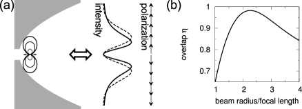
Another possibility for focusing from essentially full solid angle is using a parabolic mirror that has a depth much larger than the focal length Lindlein et al. (2007); Sondermann et al. (2007); Gardiner (1986); Bokor and Davidson (2008). As is obvious from Fig. 1, when the ratio of the depth of the parabola and the focal length surpasses the limit a parabolic mirror setup outperforms -microscopy setups. It is also evident from the figure that the configuration of a -transition with the quantization axis parallel to the mirror’s optical axis yields the largest values of for finite sized parabolic mirrors covering more than half of the solid angle.444The half solid angle case corresponds to . Therefore, we have chosen to use this configuration in our experiments Leuchs et al. (2008); Golla et al. (2012); Maiwald et al. (2012); Fischer et al. (2014).

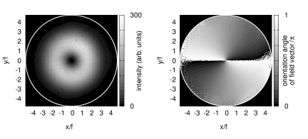
Next, we derive the field distribution to be sent onto the parabolic mirror for optimized coupling to an atom in the above configuration. Following Refs. Lindlein et al. (2007); Sondermann et al. (2008), one has to trace the emission pattern of the atomic dipole-radiation towards the parabolic surface, relating emission angles to distances from the optical axis by . Furthermore, one has to account for the proper transformation of power emitted per solid angle into power per surface area. This finally yields the amplitude distribution of a linear dipole collimated by the parabolic mirror:
| (7) |
Likewise, one finds the corresponding polarization pattern. For our configuration, the field in the exit pupil of the parabolic mirror is radially polarized. These findings are illustrated in Fig. 2.
The generation of the mode defined by Eq. 7 might be rather intricate Lindlein et al. (2007). Fortunately, there exists a mode that can have large overlaps with the ideal mode Quabis et al. (2000); Lindlein et al. (2007); Sondermann et al. (2008) and which is routinely generated in experiments: a radially polarized mode with the amplitude distribution of a Laguerre-Gaussian beam of zeroth radial and first azimuthal order. In the following, we will call this mode shortly ‘doughnut mode’ for simplicity, although the latter term is used in literature for a plethora of modes with ring shaped amplitude pattern. The amplitude distribution of a doughnut mode can be written as
| (8) |
with the beam radius . For any given parabolic mirror, the overlap parameter is maximized by tuning Sondermann et al. (2008).555This is of course also true for other focusing optics or dipole configurations and correspondingly other suitable ’standard’ field modes as e.g. a fundamental Gaussian mode, see Ref. Sondermann et al. (2008) for some examples. For our geometry ( and ) the overlap is maximized by to be % (see Fig. 2b). The intensity profile of this optimum doughnut mode is displayed as a dashed line in Fig. 2a. Using the above values of and , we could in principle achieve overall coupling efficiencies of with our setup.
However, one has to keep in mind that expanding the incident beam towards a size which maximizes might result in clipping considerable parts of the beam and hence in losses, which can be considered as a ‘no-go’ when focusing single photons onto an atom. This is a considerable effect in setups with small to medium sized numerical apertures, e.g. the NA=0.4 objectives used in Refs. Slodička et al. (2010); Piro et al. (2011). Hence it is required to maximize the product of the power transmitted through the aperture and for a given entrance pupil. However, for the parabolic mirrors used in our experiments the relative power loss for the doughnut mode with maximum is on the order of . We therefore can safely neglect such effects.
On the other side, when using doughnut modes for focusing with parabolic mirrors it is not too meaningful to use parabolic mirrors with even larger solid angle coverage than in our setup: The gain of solid angle is compensated by a reduction of the maximum value attainable for , which results in a saturation of the coupling efficiency at Sondermann et al. (2008). Of course, the latter value depends on the choice of the focusing geometry, the dipole configuration, and the optical mode used to approximate the ideal dipole radiation.
II.2 Generation and characterization of field modes tailored for efficient free-space coupling
We now turn towards the experimental generation and characterization of the optimum doughnut mode for focusing onto an atom. There are various methods for generating radially polarized doughnut modes Bomzon et al. (2002); Ghadyani et al. (2011); Stalder and Schadt (1996); Tidwell et al. (1990, 1993); Oron et al. (2000); Maurer et al. (2007); Lin et al. (2013). We have chosen to generate the doughnut mode by means of a segmented half-wave plate Dorn et al. (2003); Quabis et al. (2005). This is mainly motivated by the fact that this technique is rather robust and especially suitable for wavelengths in the ultraviolet spectral range, which we are targeting Sondermann et al. (2007); Leuchs et al. (2008); Golla et al. (2012); Maiwald et al. (2012). For details about the actually used polarization converter and the optical setup we refer to Ref. Golla et al. (2012).
One example of a generated mode is given in Fig. 3. The local intensity as well as the local polarization ellipse of the electric-field vector are obtained performing a spatially resolved measurement of the Stokes parameters (the ellipticity angle is omitted in the figure, cf. Ref. Golla et al. (2012) for details). Taking the square root of the local intensity and processing the polarization angles one can reconstruct the local electric-field vector. With the obtained field vectors one can compute the overlap with the ideal field distribution given by Eq. 7. We routinely achieve values of Golla et al. (2012) which is practically the maximum value attainable in our setup.
So far we did not discuss the properties of the phase front of the incident field. Under ideal conditions, a spherical wave emerging from the focus of the parabolic mirror leaves the mirror’s aperture with a flat phase front. Likewise the phase front of the incident field that impinges onto the mirror and is focused onto the atom should be flat. Unfortunately, current mirror manufacturing capabilities are not precise enough to guarantee the diffraction limited focusing of an incident beam that is free of aberrations. The mirrors we use in our experiments typically deviate from the parabolic shape by 150 nm Leuchs et al. (2008), which is on the order of a wavelength of the involved atomic transitions. We determine such deviations by an interferometric setup that is adapted to our purpose Leuchs et al. (2008). Other methods involving e.g. profilometers are not applicable due to the tight geometry of the used mirrors – the focal length is 2.1 mm and the aperture radius is 10 mm.
In principle the deviations of the parabolic mirror can be compensated for by using phase plates which imprint the conjugate of the mirror’s deviations onto the incident beam. Proof-of-principle experiments at a wavelength of 633 nm yielded aberration compensations enabling a Strehl ratio666 The Strehl ratio defines the maximum intensity in the focal region for a focusing system exhibiting aberrations as a fraction of the intensity obtained without aberrations Born and Wolf (1991). Whereas in the latter reference a plane wave is considered, we apply this figure of merit for the case of a doughnut mode. of 99% for a focused doughnut mode at 633 nm Golla et al. (2012).
III Overview of experiments on photon-atom coupling in free-space
In this section we discuss various kinds of experiments on photon-atom coupling in free space performed in recent years. They all have in common that the key to a successful observation of the phenomena under investigation lies in mode-matching the incident field to the dipolar radiation pattern of the addressed atomic transition. We will highlight for each type of experiment how it could benefit from full solid angle focusing or the use of parabolic mirrors, respectively.
III.1 Shifting the phase of a coherent beam
For the experiments described here – and also for the ones on attenuating a faint beam – the typical experimental setup is as follows Aljunid et al. (2009); Pototschnig et al. (2011); Hétet et al. (2013): A continuous laser beam is focused onto the atom. Depending on the detuning of the incident light with respect to the atomic resonance a certain amount of light is scattered by the atom with a detuning dependent phase shift777 The phase shift of the light scattered by an atom, i.e. the response of a driven harmonic oscillator, has been measured recently Jechow et al. (2013).. The light passing the atom and the scattered light are both collected by some optical element, e.g. a second lens of the same numerical aperture as the focusing optics. Upon diverging from the atom, the incident light suffers a phase shift of 90∘ due to the Gouy effect Zumofen et al. (2008); Tey et al. (2009); Tyc (2012). For simplicity, the latter contribution is artificially attributed to the phase of the scattered light in most literature. The phase that is then usually measured is the phase of the superposition of the scattered light and the incident light.
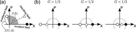
This scenario is illustrated in Fig. 4a in a phase-space picture. The phase angle of the scattered field is solely determined by the detuning , whereas the amplitude of the scattered field is determined by and especially . The latter statement is obvious from the fact that the power of the scattered light in terms of power of the incident light is given by Leuchs and Sondermann (2013); Sondermann and Leuchs (2013a) with being the rate of spontaneous emission from the excited atomic state. This so-called scattering ratio Zumofen et al. (2008); Tey et al. (2009) can be as large as four for a perfect dipole-wave incident from full solid angle and on resonance with the atomic transition.888Values for the scattering ratio exceeding unity might seem unphysical at first sight because one might suspect a violation of energy conservation. Here we argue that this is not the case. Energy is always associated with the total field not with individual interfering components. One might write a propagating field as the sum of two fields and , one 180∘ out of phase with respect to the other. The total energy has of course a well defined value. But the individual fields are not well defined. You can choose a field with a larger as long as the amplitude of field is also increased such that the sum is as before. In the specific problem of elastic scattering of a beam resonant with the atomic transition it can even be required that the scattered power has to be larger than the incident one. Due to the 180∘ phase shift between the scattered and the transmitted incident light there would otherwise be a net loss of energy under efficient-coupling conditions, since in elastic scattering no energy is transferred onto the atom. From the fact that the scattering ratio scales with the coupling efficiency one can draw the following conclusion: No matter how large the detuning is, the influence of the scattered light on the final superposition with the incident light grows with increasing and is maximized for , cf. Fig. 4 and the discussion following Eq. 9. In other words, the phase obtained for the superposition field ‘is drawn’ towards the phase of the scattered field with increasing .
In the discussion so far we have not included effects related to a finite amount of population in the atom’s excited state. The excited-state population can be quantified by using the saturation parameter , which is proportional to and depends on detuning, see also Eq. 13. This parameter influences the phase shift in two ways: For increasing saturation parameter the scattering ratio decreases. Furthermore, the scattered light contains an increasing fraction of frequency components that are not coherent with the incident light and hence cannot contribute to the superposition with the incident field. A corresponding experiment can be found in Ref. Pototschnig et al. (2011). We summarize the above discussion, assuming negligible saturation, in writing the resulting phase shift, i.e. the phase of the superposition of scattered and incident light in comparison to the case of no atom being present, as Leuchs and Sondermann (2013); Sondermann and Leuchs (2013a)
| (9) |
It is apparent from the above equation that the maximum achievable phase shift is for (resonant excitation) and . This phase arises from a phase for the coherently scattered resonant light and the Gouy phase. However, for (less than half solid angle and/or too low field overlap) the amount of scattered light is too small to counteract the incident field. For (focusing from more than half solid angle with sufficiently mode-matched incident light), the amount of scattered light is large enough to flip the phase of the superposition with the incident field. A corresponding illustration is given in Fig. 4b.
Although it seems that it is enough to have ‘ just slightly larger than ’, there are good reasons for increasing towards unity. The closer is to the smaller is the detuning interval in which increases from towards , making an experimental observation of a phase shift increasingly difficult (cf. Ref. Sondermann and Leuchs (2013a)).
The maximum phase shift observed so far in an experiment in free space was about 3∘ Pototschnig et al. (2011) using a setup with .
III.2 Extinction of a weak coherent beam
An experiment closely related to imprinting a phase shift onto a coherent beam is attenuating such a beam with a single atomVamivakas et al. (2007); Wrigge et al. (2008); Tey et al. (2008, 2009); Slodička et al. (2010); Aljunid et al. (2011); Rezus et al. (2012). In such experiments the incident beam is typically focused and recollimated with two lenses of equal numerical aperture. In the absence of the atom all light is transmitted through the two-lens setup. If an atom resides in the focus of the incident beam, the interference between incident and scattered light results in a decrease of the number of transmitted photons. The exact strength of this extinction depends again on the scattering ratio Zumofen et al. (2008); Tey et al. (2009): For focusing from half solid angle with a properly mode matched wave resulting in , the scattering ratio reaches two, with the consequence that the incident light and the light scattered into the solid angle cone of the second lens interfere destructively. In other words, a single atom can perfectly reflect a resonant coherent beam Zumofen et al. (2008); Tey et al. (2009); Kochan and Carmichael (1994). The partial reflection of an incident beam was measured in Ref. Aljunid et al. (2011). In Ref. Hétet et al. (2011) the back scattering from a single ion was exploited for utilizing a single ion as a mirror of an optical resonator (see also the chapter by Slodicka et al). The smallest transmission observed so far for a single quantum emitter in free space was about 78% Wrigge et al. (2008).
The transmitted power fraction of a resonant incident beam inducing negligible saturation of the atom can be derived straightforwardly, again assuming the same numerical aperture for focusing and light collection: The scattering ratio is given by , i.e. the light scattered into the solid angle outside the collection optics is given by . This yields
| (10) |
Obviously, for one gets full transmission. This solution is however trivial, since for a full-solid-angle optics no photons are lost due to scattering.
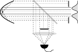
More interesting is the case of , which can be realized with a full-solid-angle parabolic mirror. If the incident light is transversely limited to exactly half of the solid angle (the portion of the parabola defined by ) one has . If furthermore one obtains and hence according to Eq. 10. In such a setup, the part of the mirror with acts as a second ‘objective’ collimating the transmitted light. A possible layout of such an experiment is sketched in Fig. 5.
III.3 Absorption of single photons
In the experiments discussed so far the light focused onto the atom was of sufficiently low intensity to avoid a non-negligible excitation of the atom, i.e., the number of photons per excited-state lifetime was much smaller than one. In contrast to this, in the experiments reported in Refs. Piro et al. (2011); Aljunid et al. (2013) the explicit aim was to excite the atom with single photons. In Ref. Piro et al. (2011) the absorption of a heralded and spectrally filtered single photon by a single ion is reported (see chapter by Piro and Eschner). The reported absorption efficiency is on the order of 0.03%. In Ref. Aljunid et al. (2013) weak coherent states have been focused onto a single atom and an absorption efficiency of about 4% is reported for pulses containing two photons on average.
As outlined in Ref. Golla et al. (2012) the probability for the absorption of a photon by a two-level atom is given by
| (11) |
The parameter describes the temporal overlap of the field envelope of the incident single photon with the field envelope that maximizes absorption. The latter is given by an increasing exponential pulse, as described in detail in the next section. According to Eq. 11 the upper bound for the absorption of single photons by atoms in our parabolic mirror setup is given by when sending the ideal radiation pattern and when sending an optimized radially-polarized doughnut mode.
We finish this section highlighting a link between the elastic scattering of a monochromatic wave discussed before and the absorption of photons, see Ref. Sondermann and Leuchs (2013b). For this purpose we treat the interaction of the atom with all spectral components of the focused pulse as an elastic scattering problem. We compute the phase and amplitude of the superposition of the incident field and the coherently scattered field for each spectral component of the incident pulse. This yields the spectrum and hence the temporal evolution of the scattered pulse. Performing such a calculation for an exponentially increasing pulse with a time constant matching the excited state’s lifetime yields an outgoing pulse envelope containing exponentially increasing and decreasing components.999The decreasing components should of course be observable for any incident pulse with non-zero temporal overlap . The fraction of the exponentially decreasing components is given by , quantifying the amount of absorbed and spontaneously re-emitted photons Sondermann and Leuchs (2013b). For full absorption is obtained, as one would expect from time-reversal symmetry arguments discussed below. But this finding should be taken with care, since time-reversal symmetry arguments demand the use of a single-photon Fock state. Nevertheless, the above treatment should be valid for weak coherent state pulses as used in Ref. Aljunid et al. (2013) or the ones created in Ref. Golla et al. (2012).
IV Absorbing a single photon: temporal mode shaping
IV.1 Choosing the right mode
As mentioned above, the temporal envelope of the focused electric field is of importance when exciting a single atom with a single photon. This can be motivated heuristically as follows (see also Refs. Quabis et al. (2000); Sondermann et al. (2007); Leuchs and Sondermann (2012)): The atom and the continuum of all free-space field modes form a closed system. For such a system, the Schrödinger equation is invariant under time reversal. Assuming the atom in its excited state and the electro-magnetic field in the vacuum state as the initial condition, a photon will be emitted spontaneously over the course of time. As is well known, a spontaneously emitted photon has an exponentially decaying field envelope with a decay constant equal to the excited-state lifetime. Applying the time reversal operation – we just assume we could do so in practice – would result in an exponentially increasing photon travelling towards the atom, promoting the atom to the excited state as outlined in Fig. 6.

Applying the time-reversal operation in practice, which implies phase-conjugating a single photon, is carefully speaking subject to technical difficulties – and also the evolution in the atom’s motional degrees of freedom has to be handled Leuchs and Sondermann (2012). Moreover, the phase-conjugation process induces excess quantum noise Yamamoto and Haus (1986); Gaeta and Boyd (1988). It is therefore the idea to shape a photon to resemble a perfect copy of a time-reversed spontaneously emitted photon.101010It can be shown in a fully quantum-mechanical calculation that an exponentially rising pulse with proper time-constant indeed leads to full excitation of the atom Stobinska et al. (2009). This implies the spatial mode-matching arguments raised in Sec. I but also requires ‘temporal mode-matching’, as expressed by the temporal overlap-parameter in Eq. 11.
In practice, the assumption of working with two-level atoms is usually not justified and there is more than one possible decay channel from the excited state. Hence, spontaneous emission would result in a superposition of the decays via all these channels, entangling the emitted photon and the remaining atom. The reverse process, absorption of a photon, would ideally start from such an entangled state. This is extremely challenging if not self forbidding. We therefore seek an atomic species providing as small as possible branching ratios in the excited state’s decay as well as a -transition. Any even numbered isotope of doubly ionized ytterbium (YbIII) is such a species. It is also a good choice from a practical point of view, since singly-ionized ytterbium (YbII) is a well-established ion used in many quantum-optics experiments and for atomic clocks. YbII also offers a strong -transition (see Fig. 10), serving as our test-system for all techniques enabling efficient free-space coupling.111111YbIII has been created by electron-impact ionization from a cloud of trapped YbII ions Schauer et al. (2010). We recently accomplished the controlled photo-ionization from YbII to YbIII.
IV.2 Generation of exponentially increasing pulses
The fact that most ions have to be addressed by ultraviolet light makes the generation of single-photon Fock states with proper temporal envelope a cumbersome task (see Ref. Golla et al. (2012) for citations on shaped photons with more ‘accessible’ wavelengths). Nevertheless, the use of whispering-gallery-mode resonators Förtsch et al. (2013) made of appropriately chosen materials might facilitate shaped single photons at UV wavelengths.
For the time being and as a preliminary test, we resort to using suitably shaped weak coherent states Golla et al. (2012). We generate these states by modulating a continuous laser beam with an acousto-optic modulator (AOM).121212A similar technique employing electro-optic modulation is reported in Ref. Dao et al. (2012). In contrast to this, other authors directly modulate the waveform of a single photon upon receiving a trigger signal from a heralding photon, see Ref. Kolchin et al. (2008) and the chapter by Chuu and Du. Last but not least, in a recent experiment single-photon Fock states with increasing exponential envelope have been achieved by manipulating a heralding photon with an asymmetric cavity prior to detection Srivathsan et al. (2014). Both photons originated from a cascaded decay in a cold atomic ensemble. The AOM is driven with a voltage signal generating exponentially rising pulses in the first diffraction order. The voltage signal is proportional to ,131313This expression arises from the fact that the power scattered into the first diffraction order of the AOM is proportional to the sine of the acoustic power establishing the diffraction grating. where is the excited-state lifetime and the frequency with which the AOM is driven. The obtained pulses are attenuated towards mean photon numbers about 0.1 and characterized by statistics on the times of photon detection events obtained from a photo-multiplier tube, cf. Ref. Golla et al. (2012) for details.
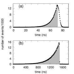
From the obtained histograms (see Fig. 7) we reconstruct the field amplitude’s envelope by taking the square root of the number of events per time bin. We then compute the overlap of with the ideal envelope obtained from time-reversal symmetry arguments:
| (12) |
For the data shown in Fig. 7 we obtain for the YbII transition and for the YbIII transition. The slightly lower overlap in the case of the YbII transition is due to the fact that the drop-off at the end of the pulse, which amounts to 5 ns enforced by the finite decay time of the acoustic grating inside the AOM, is on the order of the lifetime of 8 ns. Hence, the drop of intensity at the end of the pulse is not as step-like as required. Nevertheless, both pulse shapes envision absorption probabilities close to , neglecting the non-ideal level structure of YbII Golla et al. (2012).
IV.3 An analogous experiment: coupling to a resonator
An experiment conceptually analogous to absorbing a single photon – but with significantly reduced technical complexity – is the coupling of pulses into an empty optical resonator Heugel et al. (2010). Imagine a finite amount of energy being stored inside the resonator at a certain point in time. This electro-magnetic field will leave the resonator via exponential decay, where the time constant of the decay is given by the decay time of the intra-cavity field. If the resonator consists of only two mirrors with one of them having unit reflectivity, the field leaves the cavity through the mirror with sub-unit reflectivity. Now time-reversal arguments tell us that the energy of a properly shaped, exponentially increasing pulse sent towards the cavity is stored completely inside the cavity. In other words, no light is reflected from the cavity as long as the incident pulse continues to grow Heugel et al. (2010).
Recently, we have implemented a corresponding experiment Bader et al. (2013), shaping the pulses in the same way as described above in the generation of the weak coherent-state pulses. The non-confocal resonator, which was used in our experiment, consisted of a mirror with a reflectivity of % and % and had an intensity decay time of 39 ns. In the experiment, incident light was spatially mode matched to the resonator mode, sent onto the resonator via the mirror with reflectivity and tuned into resonance. The temporal envelope of the reflected pulse was monitored with a photo diode. The outcome of such an experiment is presented in Fig. 8.

The finite amount of light leakage through the second mirror, preventing measurements of the cavity transmission with sufficient bandwidth, as well as non-perfect spatial mode-matching necessitate a somewhat more involved analysis Bader et al. (2013). Despite the imperfections, we achieved 88% energy storage efficiency for the generated pulses and even 94% efficiency for the spatially mode-matched fraction.141414Similar efficiencies where obtained recently in experiments for microwave pulses Palomaki et al. (2013); Wenner et al. (2014). Deviations from unity are due to a non-unit temporal field overlap and leakage through the second mirror. In analogy to the single-atom experiment this leakage corresponds to a solid-angle coverage of 97%. The achieved large efficiencies hint at the power of time-reversal-symmetry based arguments when optimizing the coupling of light and matter. As a further example, true single-photon Fock states with increasing exponential temporal envelope have been efficiently coupled to a cavity recently, c.f. Ref. Liu et al. (2014).
V Trapping ions in parabolic mirrors
V.1 Parabolic mirror ion trap
So far we did not discuss a most important issue of photon-atom coupling with parabolic mirrors: How do we place the atom at the focus of the parabolic mirror? As already mentioned above, we have chosen to work with atomic ions. This demands for an ion trap potential that can be located precisely enough to place the ions within the tight focal spot of the incident beam. Simultaneously, the ion trap geometry should maintain the large solid-angle optical access to the ion. These tasks are solved by adapting a ’stylus trap’ Maiwald et al. (2009) and combining it with a parabolic mirror. The aluminium parabolic mirror replaces the planar ground electrode of the stylus trap Maiwald et al. (2009, 2012). Two tubular electrodes providing ground potential and the radio-frequency signal, respectively, are mounted concentrically and attached to a piezo-driven translation stage. The latter allows for adjusting the minimum of the trapping potential with nm-accuracy relative to the mirror’s focus. The layout is sketched in Fig. 9. The level scheme relevant for laser cooling YbII and for the coupling experiments outlined in Sec. VI is depicted in Fig. 10.
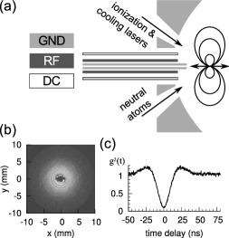
The radiation from a single YbII ion’s fluorescence as collimated by the parabolic mirror is displayed in Fig. 9b. The cooling transition has been saturated in this experiment. The figure shows an image of the intensity distribution at the output plane of the paraboloid. The spatial distribution of the measured fluorescence photons corresponds to the one of an isotropic point source, as which a saturated YbII ion can be considered Maiwald et al. (2012). The thin, concentric, ring-shaped features originate from surface distortions of the parabolic mirror, see discussion below and in Sec. VI. The central dark spot is attributed to the opening for the trap electrodes.

V.2 Fluorescence collection
The large solid angle covered by a deep parabolic mirror is not only beneficial for focusing onto an atom, but also – as suggested by the time-reversal symmetry arguments raised before – for the efficient collection of photons emerging from the atom. The latter is of importance in any application in which the internal state of an atom has to be determined.
For our mirror geometry we demonstrated the collection of 54% of the emitted fluorescence photons Maiwald et al. (2012). This number is basically limited by two constraints: As mentioned above, a saturated YbII ion emits on average as an isotropic point source. For the latter the solid angle covered by our mirror amounts to 81% instead of the 94% when considering the emission of a linear dipole aligned with the mirror’s optical axis. The second constraint stems from the surface quality of the used mirror. The nominal reflectivity of aluminium, when averaging over all angles of incidence corresponding to the surface of our mirror, should amount to roughly 87%. Instead, the measured reflectivity amounts to 67%. Such a low value is mainly attributed to a too large surface roughness of the parabolic mirror, which might be caused by a non-optimum manufacturing process. Using a mirror with better surface properties along with collecting from a linear-dipole emitter should boost the collection efficiency to 82%.
Nevertheless, according to current literature the number of two million photons per second actually counted in our setup outperforms other setups using neutral atoms or ions.
VI Experimental determination of the coupling efficiency
With the different aspects treated so far we now have basically all tools at hand for conducting experiments on efficient light-matter coupling. What we did not discuss, however, is a reliable way of determining the coupling efficiency experimentally. In principle, one could conduct the experiment one would like to do (e.g. phase shift or extinction measurements) and compare the achieved results with theory in order to find a reasonable value for that consistently reproduces the experiment. But there are some obstacles. As both the phase shift and the extinction induced by a single atom are caused by the interference of incident and scattered light, any incoherent scattering due to saturation of the atom reduces the corresponding figure of merit Wrigge et al. (2008); Pototschnig et al. (2011); Sondermann and Leuchs (2013a). Also the amount of light scattered back into the solid-angle cone of the focusing optics, as measured in Ref. Aljunid et al. (2011), is influenced by the saturation of the atom’s excited state. This is due to the fact that the scattering ratio is decreasing for increasing saturation parameter Sondermann and Leuchs (2013a); van Enk (2004).
One could solve such problems by determining the atomic saturation in an additional experiment. But there is a simpler solution in measuring only a saturation curve and relating the power needed to achieve a certain saturation parameter to the one necessary under ideal conditions, i.e. at Fischer et al. (2014). The saturation parameter induced by light with detuning and incident power is given by Sondermann and Leuchs (2013a)
| (13) |
where is the resonance frequency of the atomic transition. For example, the minimum power () to achieve a unit saturation parameter on resonance is , see also Ref. Kochan and Carmichael (1994).
In the experiment one measures the amount of fluorescence counts as a function of the incident power and fits the result to a function proportional to
| (14) |
which is the rate of photons scattered by a two-level atom in the steady state. The only difficulty arises from distinguishing the scattered photons from the incident ones. This could be done by monitoring e.g. the Stokes-shifted fluorescence when coupling to a molecule Wrigge et al. (2008). Working with YbII ions one could monitor the photons emitted on the auxiliary transition at 297 nm which is part of the typical scheme applied for laser-cooling YbII Bell et al. (1991).
Here we pursue another method and split incident and scattered light spatially. The spatial separation is accomplished by restricting the incident light to half of the solid angle as depicted in the extinction setup in Fig. 5. In other words, we cool the YbII ion with a radially polarized doughnut mode focused by the parabolic mirror while restricting the incident light to radii .151515The cooling laser beam at 370 nm that enters through an auxiliary opening of the parabolic mirror (cf. Fig. 9) is blocked during the saturation measurements. Furthermore, one has to use the same kind of aperture in the detection path as in the excitation path in order to detect only backward scattered light Fischer et al. (2014). The result of such an experiment is given in Fig. 11.
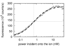
A least-squares fit yields a power of 690 pW for achieving . Using the parameters 8.1 ns, and 370 nm Eq. 13 thus delivers . However, we have to take into account that Eq. 13 is valid for a two-level atom, which is not the appropriate description of YbII. The focused radially polarized mode only drives the -transition which has a relative oscillator strength of in comparison to for the -transitions for the levels and . Hence we have to apply a correction factor of three in order to obtain .161616This reasoning assumes that the quantization axis is parallel to the optical axis of the parabola. But one can show that for any orientation of the quantization axis the same correction factor has to be applied when treating a transition.
This coupling efficiency is among the largest achieved in a free-space setup so far, but it is seven times below the expected value: Focusing from half solid angle, the maximum achievable coupling efficiency amounts to . The non-perfect overlap of measured for the incident doughnut modes is so close to the ideal value that it can only explain a tiny portion of the discrepancy. Most probably the discrepancy arises from the fact that the aberrations of the non-perfect parabolic surface have not been compensated during the measurement. From an interferometric characterizationLeuchs et al. (2008) of the parabolic mirror performed before mounting it in the vacuum chamber and simulations of the focal intensity based on the corresponding results we predict a Strehl ratio of 87% for focusing from . The obtainable coupling efficiency including the aberrations and thus amounts to 41%.
This value is still much larger than the measured one. We speculate that the surface of the parabolic mirror might be subjected to unknown distortions which are not recognizable in the interferometric measurements performed at visible wavelengths. But also distortions of the incident wavefront by the viewport of the vacuum chamber might play a role. In any case, the measurement of the coupling efficiency as performed here provides a sensitive tool hinting at any open issues.
VII Outlook
The experimental demonstrations of coupling light to a single atom in free space have been made with different systems. The best experimental performance in relation to the phase shift of the full transmitted beam, the extinction of the irradiating beam and the absorption of a single photon are are still far from the theoretical best possible values and thus far away from the maximum possible efficiency. The parabolic mirror set-up emphasized here offers the opportunity of improving upon all these numbers. Nevertheless, demonstrating close to 100% absorption efficiency remains a particular challenge, since the requirements on mode-matching in the spatial and temporal domain have to be fulfilled with highest quality. This is especially difficult at the short wavelength of the linear-dipole transition of the almost ideal two-level system YbIII, which we successfully trapped recently. We hope to report on light-matter-interaction experiments with a single YbIII ion in the near future.
Acknowledgements.
We gratefully acknowledge the contributions of Marianne Bader, Benoit Chalopin, Martin Fischer, Andrea Golla, Simon Heugel and Robert Maiwald to our experimental endeavours. We thank the Deutsche Forschungsgemeinschaft for financial support. G.L. also acknowledges financial support from the European Research Council under the Advanced Grant ‘PACART’.References
- Mandel and Wolf (1995) L. Mandel and E. Wolf, Optical Coherence and Quantum Optics (Cambridge University Press, Cambridge, New York, 1995).
- Scully and Zubairy (1997) M. O. Scully and M. S. Zubairy, Quantum Optics (Cambridge University Press, Cambridge, 1997).
- Moskovits (1985) M. Moskovits, Rev. Mod. Phys. 57, 783 (1985).
- Kühn et al. (2006) S. Kühn, U. Håkanson, L. Rogobete, and V. Sandoghdar, Phys. Rev. Lett. 97, 017402 (2006).
- Novotny and van Hulst (2011) L. Novotny and N. van Hulst, Nature Photonics 5, 83 (2011).
- Raimond et al. (2001) J. M. Raimond, M. Brune, and S. Haroche, Rev. Mod. Phys. 73, 565 (2001).
- Walther et al. (2006) H. Walther, B. T. H. Varcoe, B.-G. Englert, and T. Becker, Rep. Prog. Phys. 69, 1325 (2006).
- Kimble (1998) H. J. Kimble, Physica Scripta T76, 127 (1998).
- Rempe (1993) G. Rempe, Contemporary Physics 34, 119 (1993).
- Sondermann et al. (2007) M. Sondermann, R. Maiwald, H. Konermann, N. Lindlein, U. Peschel, and G. Leuchs, Appl. Phys. B 89, 489 (2007), arxiv:0708.0772 .
- Specht et al. (2011) H. Specht, C. Nölleke, A. Reiserer, M. Uphoff, E. Figueroa, S. Ritter, and G. Rempe, Nature 473, 190 (2011).
- Ritter et al. (2012) S. Ritter, C. Nölleke, C. Hahn, A. Reiserer, A. Neuzner, M. Uphoff, M. Mücke, E. Figueroa, J. Bochmann, and G. Rempe, Nature 484, 195 (2012), arXiv:1202.5955 .
- Sames et al. (2014) C. Sames, H. Chibani, C. Hamsen, P. A. Altin, T. Wilk, and G. Rempe, Phys. Rev. Lett. 112, 043601 (2014).
- Tiecke et al. (2014) T. Tiecke, J. Thompson, N. de Leon, L. Liu, V. Vuletić, and M. Lukin, Nature 508, 241 (2014).
- Quabis et al. (2000) S. Quabis, R. Dorn, M. Eberler, O. Glöckl, and G. Leuchs, Opt. Comm. 179, 1 (2000).
- Leuchs and Sondermann (2012) G. Leuchs and M. Sondermann, Physica Scripta 85, 058101 (2012), arXiv:1205.1374 .
- Leuchs and Sondermann (2013) G. Leuchs and M. Sondermann, Journal of Modern Optics 60, 36 (2013).
- Silberfarb and Deutsch (2003) A. Silberfarb and I. H. Deutsch, Phys. Rev. A 68, 013817 (2003).
- Pinotsi and Imamoglu (2008) D. Pinotsi and A. Imamoglu, Phys. Rev. Lett. 100, 093603 (2008).
- Cohen-Tannoudji et al. (1989) C. Cohen-Tannoudji, J. Dupont-Roc, and G. Grynberg, Photons and atoms (J. Wiley and Sons, 1989).
- Basset (1986) I. M. Basset, Journal of Modern Optics 33, 279 (1986).
- van Enk (2004) S. J. van Enk, Phys. Rev. A 69, 043813 (2004).
- Wang et al. (2011) Y. Wang, J. Minář, L. Sheridan, and V. Scarani, Phys. Rev. A 83, 063842 (2011).
- Sondermann et al. (2008) M. Sondermann, N. Lindlein, and G. Leuchs, arXiv:0811.2098 [physics.optics] (2008).
- Jackson (1999) J. D. Jackson, Classical Electrodynamics, 3rd ed. (Wiley, New York, 1999).
- Fischer et al. (2014) M. Fischer, M. Bader, R. Maiwald, A. Golla, M. Sondermann, and G. Leuchs, Appl. Phys. B 117, 797 (2014), arXiv:1311.1982 .
- Lindlein et al. (2007) N. Lindlein, R. Maiwald, H. Konermann, M. Sondermann, U. Peschel, and G. Leuchs, Laser Physics 17, 927 (2007).
- Golla et al. (2012) A. Golla, B. Chalopin, M. Bader, I. Harder, K. Mantel, R. Maiwald, N. Lindlein, M. Sondermann, and G. Leuchs, Eur. Phys. J. D 66, 190 (2012), arXiv:1207.3215 .
- Hell and Stelzer (1992) S. Hell and E. H. K. Stelzer, J. Opt. Soc. Am. A 9, 2159 (1992).
- Tey et al. (2008) M. K. Tey, Z. Chen, S. A. Aljunid, B. Chng, F. Huber, G. Maslennikov, and C. Kurtsiefer, Nature Physics 4, 924 (2008).
- Piro et al. (2011) N. Piro, F. Rohde, C. Schuck, M. Almendros, J. Huwer, J. Ghosh, A. Haase, M. Hennrich, F. Dubin, and J. Eschner, Nat. Phys. 7, 17 (2011).
- Aljunid et al. (2013) S. A. Aljunid, G. Maslennikov, Y. Wang, H. L. Dao, V. Scarani, and C. Kurtsiefer, Phys. Rev. Lett. 111, 103001 (2013), arXiv:1304.3761 .
- Gardiner (1986) C. W. Gardiner, Phys. Rev. Lett. 56, 1917 (1986).
- Bokor and Davidson (2008) N. Bokor and N. Davidson, Opt. Commun. 281, 5499 (2008).
- Leuchs et al. (2008) G. Leuchs, K. Mantel, A. Berger, H. Konermann, M. Sondermann, U. Peschel, N. Lindlein, and J. Schwider, Applied Optics 47, 5570 (2008).
- Maiwald et al. (2012) R. Maiwald, A. Golla, M. Fischer, M. Bader, S. Heugel, B. Chalopin, M. Sondermann, and G. Leuchs, Phys. Rev. A 86, 043431 (2012).
- Slodička et al. (2010) L. Slodička, G. Hétet, S. Gerber, M. Hennrich, and R. Blatt, Phys. Rev. Lett. 105, 153604 (2010).
- Bomzon et al. (2002) Z. Bomzon, G. Biener, V. Kleiner, and E. Hasman, Opt. Lett. 27, 285 (2002).
- Ghadyani et al. (2011) Z. Ghadyani, I. Vartiainen, I. Harder, W. Iff, A. Berger, N. Lindlein, and M. Kuittinen, Appl. Opt. 50, 2451 (2011).
- Stalder and Schadt (1996) M. Stalder and M. Schadt, Opt. Lett. 21, 1948 (1996).
- Tidwell et al. (1990) S. Tidwell, D. Ford, and W. Kimura, Applied Optics 29, 2234 (1990).
- Tidwell et al. (1993) S. Tidwell, G. Kim, and W. Kimura, Applied Optics 32, 5222 (1993).
- Oron et al. (2000) R. Oron, S. Blit, N. Davidson, A. Friesem, Z. Bomzon, and E. Hasman, Applied Physics Letters 77, 3322 (2000).
- Maurer et al. (2007) C. Maurer, A. Jesacher, S. Fürhapter, S. Bernet, and M. Ritsch-Marte, New Journal of Physics 9, 78 (2007).
- Lin et al. (2013) J. Lin, P. Genevet, M. A. Kats, N. Antoniou, and F. Capasso, Nano letters 13, 4269 (2013).
- Dorn et al. (2003) R. Dorn, S. Quabis, and G. Leuchs, Phys. Rev. Lett. 91, 233901 (2003).
- Quabis et al. (2005) S. Quabis, R. Dorn, and G. Leuchs, Appl. Phys. B 81, 597 (2005).
- Born and Wolf (1991) M. Born and E. Wolf, Principles of optics, 6th ed. (Pergamon Press, Oxford, 1991).
- Aljunid et al. (2009) S. A. Aljunid, M. K. Tey, B. Chng, T. Liew, G. Maslennikov, V. Scarani, and C. Kurtsiefer, Physical Review Letters 103, 153601 (2009).
- Pototschnig et al. (2011) M. Pototschnig, Y. Chassagneux, J. Hwang, G. Zumofen, A. Renn, and V. Sandoghdar, Phys. Rev. Lett. 107, 063001 (2011).
- Hétet et al. (2013) G. Hétet, L. Slodička, N. Röck, and R. Blatt, Phys. Rev. A 88, 041804 (2013).
- Jechow et al. (2013) A. Jechow, B. G. Norton, S. Händel, V. Blūms, E. W. Streed, and D. Kielpinski, Phys. Rev. Lett. 110, 113605 (2013), arXiv:1208.5091 .
- Zumofen et al. (2008) G. Zumofen, N. M. Mojarad, V. Sandoghdar, and M. Agio, Phys. Rev. Lett. 101, 180404 (2008).
- Tey et al. (2009) M. K. Tey, G. Maslennikov, T. C. H. Liew, S. A. Aljunid, F. Huber, B. Chng, Z. Chen, V. Scarani, and C. Kurtsiefer, New Journal of Physics 11, 043011 (2009).
- Tyc (2012) T. Tyc, Opt. Lett. 37, 924 (2012).
- Sondermann and Leuchs (2013a) M. Sondermann and G. Leuchs, J. Europ. Opt. Soc. Rap. Public. 8, 13502 (2013a), arXiv:1306.2804 [quant-ph] .
- Vamivakas et al. (2007) A. N. Vamivakas, M. Atatüre, J. Dreiser, S. T. Yilmaz, A. Badolato, A. K. Swan, B. B. Goldberg, A. Imamoglu, and M. S. Ünlü, Nano Letters 7, 2892 (2007).
- Wrigge et al. (2008) G. Wrigge, I. Gerhardt, J. Hwang, G. Zumofen, and V. Sandoghdar, Nature Physics 4, 60 (2008).
- Aljunid et al. (2011) S. A. Aljunid, B. Chng, J. Lee, M. Paesold, G. Maslennikov, and C. Kurtsiefer, Journal of Modern Optics 58, 299 (2011).
- Rezus et al. (2012) Y. L. A. Rezus, S. G. Walt, R. Lettow, A. Renn, G. Zumofen, S. Götzinger, and V. Sandoghdar, Phys. Rev. Lett. 108, 093601 (2012).
- Kochan and Carmichael (1994) P. Kochan and H. J. Carmichael, Phys. Rev. A 50, 1700 (1994).
- Hétet et al. (2011) G. Hétet, L. Slodička, M. Hennrich, and R. Blatt, Phys. Rev. Lett. 107, 133002 (2011).
- Sondermann and Leuchs (2013b) M. Sondermann and G. Leuchs, Romanian Reports in Physics 65, 638 (2013b), arXiv:1306.3902 [quant-ph] .
- Yamamoto and Haus (1986) Y. Yamamoto and H. A. Haus, Rev. Mod. Phys. 58, 1001 (1986).
- Gaeta and Boyd (1988) A. L. Gaeta and R. W. Boyd, Phys. Rev. Lett. 60, 2618 (1988).
- Stobinska et al. (2009) M. Stobinska, G. Alber, and G. Leuchs, EPL 86, 14007 (2009), arxiv:0808.1666 .
- Schauer et al. (2010) M. M. Schauer, J. R. Danielson, D. Feldbaum, M. S. Rahaman, L.-B. Wang, J. Zhang, X. Zhao, and J. R. Torgerson, Phys. Rev. A 82, 062518 (2010).
- Förtsch et al. (2013) M. Förtsch, J. U. Fürst, C. Wittmann, D. Strekalov, A. Aiello, M. V. Chekhova, C. Silberhorn, G. Leuchs, and C. Marquardt, Nature communications 4, 1818 (2013).
- Dao et al. (2012) H. L. Dao, S. A. Aljunid, G. Maslennikov, and C. Kurtsiefer, Review of Scientific Instruments 83, 083104 (2012).
- Kolchin et al. (2008) P. Kolchin, C. Belthangady, S. Du, G. Y. Yin, and S. E. Harris, Phys. Rev. Lett. 101, 103601 (2008).
- Srivathsan et al. (2014) B. Srivathsan, G. K. Gulati, A. Cerè, B. Chng, and C. Kurtsiefer, Phys. Rev. Lett. 113, 163601 (2014).
- Heugel et al. (2010) S. Heugel, A. S. Villar, M. Sondermann, U. Peschel, and G. Leuchs, Laser Physics 20, 100 (2010), arXiv:1009.2365 .
- Bader et al. (2013) M. Bader, S. Heugel, A. L. Chekhov, M. Sondermann, and G. Leuchs, New Journal of Physics 15, 123008 (2013), arXiv:1309.6167 [physics.optics] .
- Palomaki et al. (2013) T. Palomaki, J. Harlow, J. Teufel, R. Simmonds, and K. Lehnert, Nature 495, 210 (2013).
- Wenner et al. (2014) J. Wenner, Y. Yin, Y. Chen, R. Barends, B. Chiaro, E. Jeffrey, J. Kelly, A. Megrant, J. Y. Mutus, C. Neill, P. J. J. O’Malley, P. Roushan, D. Sank, A. Vainsencher, T. C. White, A. N. Korotkov, A. N. Cleland, and J. M. Martinis, Phys. Rev. Lett. 112, 210501 (2014).
- Liu et al. (2014) C. Liu, Y. Sun, L. Zhao, S. Zhang, M. M. T. Loy, and S. Du, Phys. Rev. Lett. 113, 133601 (2014).
- Maiwald et al. (2009) R. Maiwald, D. Leibfried, J. Britton, J. C. Bergquist, G. Leuchs, and D. J. Wineland, Nature Physics 5, 551 (2009), arxiv:0810.2647 .
- Bell et al. (1991) A. S. Bell, P. Gill, H. A. Klein, A. P. Levick, C. Tamm, and D. Schnier, Phys. Rev. A 44, 20 (1991).