Aerodynamically-Optimal Hovering Is Not Stable
Optimal Hovering Conditions Are Not Stable
Stable Hovering is Not Aerodynamically-Optimal
Stability versus Maneuverability in Hovering Flight
Abstract
Insects and birds are often faced by opposing requirements for agile and stable flight. Here, we explore the interplay between aerodynamic effort, maneuverability, and stability in a model system that consists of a -shaped flyer hovering in a vertically oscillating airflow. We determine effective conditions that lead to periodic hovering in terms of two parameters: the flyer’s shape (opening angle) and the effort (flow acceleration) needed to keep the flyer aloft. We find optimal shapes that minimize effort. We then examine hovering stability and observe a transition from unstable, yet maneuverable, to stable hovering. Interestingly, this transition occurs at post-optimal shapes, that is, at increased aerodynamic effort. These results have profound implications on the interplay between stability and maneuverability in live organisms as well as on the design of man-made air vehicles.
pacs:
47.63.-b, 47.15.ki, 47.15.km, 47.20.Cq, 47.20.KyThe unsteady flow-structure interactions in flapping wing motions produce lift and thrust forces that allow insects and birds to fly forward or hover in place. The mechanisms responsible for the generation of these aerodynamic forces received a great deal of attention in recent experimental Ellington et al. (1996); Dickinson et al. (1999); Spedding et al. (2003); Birch and Dickinson (2003); Thomas et al. (2004); Warrick et al. (2005) and theoretical Ramamurti and Sandberg (2002); Minotti (2002); Sun and Tang (2002); Sun and Lan (2004); Wang (2000a, b); Wang et al. (2004); Wang and Russell (2007); Spagnolie and Shelley (2009) studies, mostly emphasizing the importance of leading-edge and wake vorticity in force production Sane (2003); Wang (2005). However, the stability of flapping flight in response to environmental disturbances is less well explored Sun (2014). Recent studies report conflicting accounts of intrinsic instability Sun and Xiong (2005); Sun et al. (2007); Faruque and Humbert (2010); Wu and Sun (2012) and passive stability Taylor and Thomas (2002); Taylor and Żbikowski (2005); Ristroph et al. (2013).
Live organisms certainly employ active feedback control during flight Ristroph et al. (2010); Gillies et al. (2011), but it is not clear to what extent. Active stabilization requires additional effort and thus energy expenditure. One can thus argue that passive stability reduces the effort required for flying. In this sense, it seems reasonable to conjecture that, from an evolutionary perspective, passive stability may have a positive selection value. However, stability can be thought of as “resistance to change” which conflicts with maneuverability Taylor and Thomas (2002); Dudley (2002). Unlike stability, there is no clear quantitative definition of maneuverability, which we consider here to simply mean lack of stability. Stable motions require extra effort to change, which could make sudden maneuvers energetically costly, whereas an unstable motion only needs a slight perturbation to change because the aerodynamic forces help in moving the system away from its current state, making it easier to maneuver. Basically, there is a tradeoff between the effort required to maintain an unstable motion and that of causing a stable motion to change – that is to say, a trade-off between stability and maneuverability.
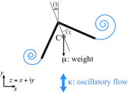
Whereas an assessment of the passive stability of live organisms is not feasible experimentally, an ingenious model system of an inanimate flyer was proposed recently as a proxy to flapping flight Childress et al. (2006); Weathers et al. (2010); Liu et al. (2012). The experimental model consists of an upward-pointing pyramid-shaped object in a vertically oscillating airflow Weathers et al. (2010); Liu et al. (2012). The inanimate flyer generates sufficient aerodynamic force to keep aloft and maintains balance passively during free flight. In Liu et al. (2012), the authors use clever arguments and simplifying approximations founded on a deep understanding of aerodynamics to obtain “educated guesses” of the stabilizing mechanism without ever solving the coupled flow-structure interactions. In this work, we formulate a two-dimensional model of a -shaped object in an oscillating uniform flow, see Fig. 1. This formulation enables us to quantitatively examine the aerodynamic forces required to keep the flyer aloft and the stabilizing aerodynamic moments. Most importantly, it provides a quantitative framework for exploring aerodynamic-optimal hovering conditions and for rigorously studying the transition from unstable, yet more maneuverable, to stable hovering.

Our model -flyer consists of two flat plates, of equal length and total mass , joined at the apex at an angle , see Fig. 1. The background fluid of density oscillates vertically with velocity , where is the oscillation frequency and is the top-bottom oscillation amplitude. Four relevant dimensionless parameters can be constructed: the mass and weight of the -flyer, and the amplitude and acceleration of the background flow oscillations. Note that the parameter can be interpreted as a measure of the effort needed to keep the flyer aloft.
Let denote the position of the mass center of the -flyer in the complex -plane () and let denote its orientation from the upward vertical (Fig. 1). The equations governing its free motion under the effects of gravitational and aerodynamic forces are
| (1) |
where is the dimensionless moment of inertia, , and are the aerodynamic forces and torque.
We simulate the flow using a vortex sheet model in the inviscid fluid context. The -flyer is modeled as a bound vortex sheet that satisfies zero normal flow through the flyer. A point vortex is released at each time step from the two outer edges of the -flyer, and the shed vorticity is modeled as a regularized free sheet Krasny (1986); Nitsche and Krasny (1994); Jones (2003); Jones and Shelley (2005); Alben and Shelley (2008); Michelin et al. (2008). No separation is allowed at the apex. Here, we follow the algorithm in Nitsche and Krasny (1994) for imposing the Kutta condition that determines the amount of circulation shed from the outer two edges at each time step. The vortex sheet model depends on the regularization parameter for the free sheet, which in the results below is set to . By way of validation, we confirmed that our numerical scheme gives identical results for examples presented in Jones (2003); Jones and Shelley (2005) of driven flat plates and plates freely falling under gravity, even though the implementation details differ significantly. Finally, to emulate the effect of viscosity, we allow the shed vortex sheet to decay gradually by dissipating each incremental point vortex after a finite time from the time it is shed in the fluid. Larger implies lower fluid viscosity. A closed-form expression that rigorously links to the kinematic fluid viscosity is not readily available, however, using approximate arguments based on the Lamb-Oseen solution, we choose such that is small, where is the normalized viscosity of air.

We first examine the behavior of a flyer undergoing periodic hovering motion. Fig. 2(a) depicts snapshots of the hovering motion and vortical wake for a flyer with angle and mass in an oscillating flow of amplitude , acceleration , and dissipation parameter . The total simulation time is , where is the oscillation period of the background flow. The flyer is subject to zero initial velocity and tilt conditions . Clearly, during the up-flow, vortices are generated at the two outer edges of the flyer. These vortices combine with the vortices generated during the down-flow to form two vortex dipoles that initially move vertically down. This downwash results in a lift force that balances the weight of the flyer keeping it aloft, as noted qualitatively in Liu et al. (2012) . Quantitatively, the aerodynamic torque and horizontal force acting on the flyer are identically zero as expected from symmetry considerations while the vertical force oscillates periodically from positive to negative at the same frequency as the background flow such that its -averaged value when normalized by the flyer’s weight is equal to (Fig 3(a)). Vortex shedding is essential for the generation of these lift forces. The flyer responds by oscillating up and down at speeds smaller than those of the background oscillatory flow (Fig 3(b)) such that it hovers around its initial vertical position (Fig 3(c)). By hovering, we mean that the change in the -averaged vertical position is equal to zero.
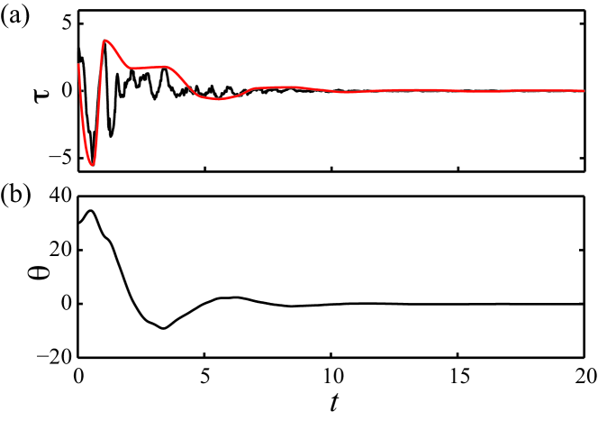
This hovering motion is stable to initial perturbation, which we impose here on the initial tilt angle . Surprisingly, the flyer recovers the upright orientation and continues to hover stably for a range of initial perturbations as large as . For , snapshots of the flyer and its wake during the recovery phase are depicted in Fig. 2(b). When the flyer is tilted to one side, the left-right symmetry of the shed vorticity is broken, which leads to stronger vorticity shed sideways from the edge with the larger angle of attack. The sideward vorticity creates a restorative aerodynamic torque as argued qualitatively in Liu et al. (2012) and depicted quantitatively in Fig. 4. Here, both the torque envelope (shown in red line) and the orientation of the flyer fluctuate out of phase relative to each other, indicating the restorative effect of the aerodynamic torque. The fluctuations decrease in amplitude and eventually approach zero as the flyer recovers its upright orientation.
We now determine effective conditions for hovering as a function of two parameters: the flyer’s shape described by the opening angle and the effort needed of the oscillating flow expressed by the flow acceleration parameter . We set , and we vary from to and from to . Note that, for a flyer of a given shape, there is an associated effort or flow acceleration that keeps the flyer aloft when starting in its upright position with zero initial velocity. Stronger or weaker efforts would cause the flyer to ascend or descend. That is to say, each point in the parameter space represents one of three types of behavior: ascending , hovering or descending . The hovering condition defines a hovering curve in the -plane as depicted in Fig. 5 for three cases: and , corresponding to decreasing fluid “viscosity.” In all three cases, there exists an optimal shape hovering curve admits a global minimum , that is, for which the effort required to hover is minimum. The value of the minimum effort decreases as the “viscosity” decreases, which can be intuitively understood on the ground that, at lower viscosity, the shed vortices responsible for the lift production are longer lived.

We then analyze the passive stability of all points on the hovering curve by imposing a small initial perturbation and solving the fully nonlinear governing equations of motion in (1). In particular, we focus on the time evolution of the tilt angle : if it oscillates with decreasing or constant amplitude, we say the flyer is passively stable. If the amplitude of grows in time, the flyer is unstable. By mapping out these stability results to the hovering curves in Fig. 5, we see a transition from unstable to stable hovering as the opening angle of the flyer increases. Most importantly, the transition from unstable to stable hovering occurs at a critical shape that is post-optimal (). This result leads to interesting insights on the interplay between maneuverability and stability in hovering flights.
-flyers with optimal shapes operating at minimum aerodynamic effort produce hovering motions that are passively unstable. One should therefore be careful when optimizing for aerodynamic effort alone without paying attention to motion stability. In so doing, one would obtain optimal flyers that, although more maneuverable, would require active stabilization mechanisms. Active stabilization requires aerodynamic effort that may be even larger than the effort required for passive stability. This interpretation assumes that, when evaluating or designing flyers, one should opt for either stability or maneuverability. However, the results in Fig. 5 lend themselves to a far richer explanation. They suggest that a -flyer that could actively change its shape, as in the case of live organisms, can smoothly switch from passively stable to unstable, yet more maneuverable, states by decreasing its opening angle. They also suggest that, although passive stability is not free (it comes at a higher effort ), switching from stable to maneuverable states requires no extra effort, it rather requires a decrease in the aerodynamic effort because the transition occurs post-optimally for . Accordingly, we conjecture that, to fulfill the two requirements of passive stability and maneuverability, a good design practice both in nature and in man-made aerial vehicles is to position the stability limit at a post-optimal location in the parameter space.
Future extensions of this work will include studying the effects of body deformation and body elasticity on the aerodynamic effort and stability of flapping flight, both in two- and three-dimensions.
References
- Ellington et al. (1996) C. P. Ellington, C. van den Berg, A. P. Willmott, and A. L. R. Thomas, Nature 384, 626 (1996).
- Dickinson et al. (1999) M. H. Dickinson, F.-O. Lehmann, and S. P. Sane, Science 284, 1954 (1999).
- Spedding et al. (2003) G. Spedding, M. Rosén, and A. Hedenström, J. Exp. Biol. 206, 2313 (2003).
- Birch and Dickinson (2003) J. M. Birch and M. H. Dickinson, J. Exp. Biol. 206, 2257 (2003).
- Thomas et al. (2004) A. L. R. Thomas, G. K. Taylor, R. B. Srygley, R. L. Nudds, and R. J. Bomphrey, J. Exp. Biol. 207, 4299 (2004).
- Warrick et al. (2005) D. R. Warrick, B. W. Tobalske, and D. R. Powers, Nature 435, 1094 (2005).
- Ramamurti and Sandberg (2002) R. Ramamurti and W. C. Sandberg, J. Exp. Biol. 205, 1507 (2002).
- Minotti (2002) F. O. Minotti, Phys. Rev. E 66, 051907 (2002).
- Sun and Tang (2002) M. Sun and J. Tang, J. Exp. Biol. 205, 55 (2002).
- Sun and Lan (2004) M. Sun and S. L. Lan, J. Exp. Biol. 207, 1887 (2004).
- Wang (2000a) Z. J. Wang, Phys. Rev. Lett. 85, 2216 (2000a).
- Wang (2000b) Z. J. Wang, J. Fluid Mech. 410, 323 (2000b).
- Wang et al. (2004) Z. J. Wang, J. M. Birch, and M. H. Dickinson, J. Exp. Biol. 207, 449 (2004).
- Wang and Russell (2007) Z. J. Wang and D. Russell, Phys. Rev. Lett. 99, 148101 (2007).
- Spagnolie and Shelley (2009) S. E. Spagnolie and M. J. Shelley, Phys. Fluids 21, 013103 (2009).
- Sane (2003) S. P. Sane, J. Exp. Biol. 206, 4191 (2003).
- Wang (2005) Z. J. Wang, Annu. Rev. Fluid Mech. 37, 183 (2005).
- Sun (2014) M. Sun, Rev. Mod. Phys. 86, 615 (2014).
- Sun and Xiong (2005) M. Sun and Y. Xiong, J. Exp. Biol. 208, 447 (2005).
- Sun et al. (2007) M. Sun, J. Wang, and Y. Xiong, Acta Mech. Sin. 23, 231 (2007).
- Faruque and Humbert (2010) I. Faruque and J. S. Humbert, J. Theor. Biol. 264, 538 (2010).
- Wu and Sun (2012) J. H. Wu and M. Sun, J. R. Soc. Interface 9, 2033 (2012).
- Taylor and Thomas (2002) G. K. Taylor and A. L. R. Thomas, J. Theor. Biol. 214, 351 (2002).
- Taylor and Żbikowski (2005) G. K. Taylor and R. Żbikowski, J. R. Soc. Interface 2, 197 (2005).
- Ristroph et al. (2013) L. Ristroph, G. Ristroph, S. Morozova, A. J. Bergou, S. Chang, J. Guckenheimer, Z. J. Wang, and I. Cohen, J. R. Soc. Interface 10, 20130237 (2013).
- Ristroph et al. (2010) L. Ristroph, A. J. Bergou, G. Ristroph, K. Coumes, G. J. Berman, J. Guckenheimer, Z. J. Wang, and I. Cohen, Proc. Natl. Acad. Sci. U.S.A. 107, 4820 (2010).
- Gillies et al. (2011) J. A. Gillies, A. L. R. Thomas, and G. K. Taylor, J. Avian Biol. 42, 377 (2011).
- Dudley (2002) R. Dudley, Integr. Comp. Biol. 42, 135 (2002).
- Childress et al. (2006) S. Childress, N. Vandenberghe, and J. Zhang, Phys. Fluids 18, 117103 (2006).
- Weathers et al. (2010) A. Weathers, B. Folie, B. Liu, S. Childress, and J. Zhang, J. Fluid Mech. 650, 415 (2010).
- Liu et al. (2012) B. Liu, L. Ristroph, A. Weathers, S. Childress, and J. Zhang, Phys. Rev. Lett. 108, 068103 (2012).
- Krasny (1986) R. Krasny, J. Comput. Phys. 65, 292 (1986).
- Nitsche and Krasny (1994) M. Nitsche and R. Krasny, J. Fluid Mech. 276, 139 (1994).
- Jones (2003) M. A. Jones, J. Fluid Mech. 496, 405 (2003).
- Jones and Shelley (2005) M. A. Jones and M. J. Shelley, J. Fluid Mech. 540, 393 (2005).
- Alben and Shelley (2008) S. Alben and M. J. Shelley, Phys. Rev. Lett. 100, 074301 (2008).
- Michelin et al. (2008) S. Michelin, S. G. Llewellyn Smith, and B. J. Glover, J. Fluid Mech. 617, 1 (2008).