Length control of an optical resonator using second-order transverse modes
Abstract
We present the analysis of an unorthodox technique for locking a laser to a resonant optical cavity. Error signals are derived from the interference between the fundamental cavity mode and higher-order spatial modes of order two excited by mode mismatch. This scheme is simple, inexpensive and, in contrast to similar techniques, first-order-insensitive to beam jitter. After mitigating sources of technical noise, performance is fundamentally limited by quantum shot-noise.
Massachusetts
Institute of Technology, Cambridge, MA 02139,
USA
∗Corresponding author: jmiller@ligo.mit.edu
120.2230, 140.4780, 120.3180.
Due to their power gain and non-linear phase response, resonant optical cavities are routinely employed across a variety of fields. However, to exploit these useful properties, cavities must be held resonant with their input laser fields using a feedback control system, a process known as locking.
In order to achieve lock, a suitable error signal, describing the offset of the incoming laser light from resonance, must be generated. This procedure ordinarily involves comparing light which interacts strongly with the cavity to a stable reference. Common references include a fixed voltage source (side-of-fringe locking) and audio- or radio-frequency modulation sidebands (dither and Pound-Drever-Hall locking respectively) [1]. More infrequently, polarisation effects are also used to create locking references (see e.g. [2, 3]).
This Letter analyses the use of a higher-order Laguerre-Gaussian () mode of order two [4], excited by mode mismatch, as an alternative reference for cavity locking. We introduce a theoretical scheme for generating error signals from this reference and discuss two practical methods of implementing it. Experimental investigation confirms our predictions.
As recognised previously [5], techniques based on higher-order modes (HOMs) are particularly appealing because they remove the need for external references or modulation-demodulation stages whilst maintaining the ability to lock to the top of a resonance peak. Hence these techniques offer good sensitivity, are relatively simple and inexpensive, consume little electrical power, are low-weight, do not require small-aperture modulators in the beam path and are robust against temperature fluctuations. In addition to general laboratory applications, these properties make HOM-based techniques ideal for field-deployable (including satellite-based) instruments, high-power systems and experiments requiring multiple control loops.
Moreover, in contrast to prior investigations [6], which made use of an odd-order HOM as a locking reference, our technique is first-order insensitive to beam spot motion at the detector. This robustness is particularly beneficial in industrial and suspended-mirror environments.
An optical cavity will decompose any input beam into its cavity eigenmodes. Our analysis considers a rotationally-symmetric input beam which is perfectly aligned to the axis of a spherical-mirror cavity (the axis) but whose beam parameters differ slightly from those of the fundamental cavity mode. In this case, the cavity eigenmodes excited by the mismatched input beam are well-approximated by the family of modes.
For small (first order in the perturbation) mode mismatches only coupling to the two lowest order modes need be considered. Neglecting common phase factors irrelevant to our analysis, these modes may be expressed as
| (1) | ||||
| (2) |
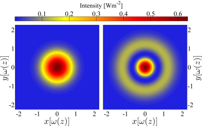
where is the beam spot size ( being the beam waist; , the Rayleigh range), is the Gouy phase and subscripts indicate the mode order . The intensity distribution of each of these modes is shown in Fig. 1.
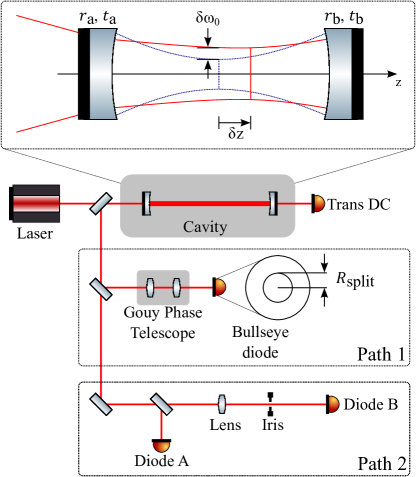
Consider a cavity with waist at position . In the basis of cavity eigenmodes, a 1 W, fundamental mode, input beam with waist size at position (see Fig. 2) may be described as
| (3) | ||||
| (4) |
and [7].
Our scheme generates error signals via the light reflected from a resonant optical cavity. The complex amplitude reflectivity of a cavity is given by
| (5) |
where is the phase acquired upon one cavity round-trip, and are the amplitude reflection and transmission coefficients of the input mirror and is the reflection coefficient of the end mirror.
In stable cavities the eigenmodes are not degenerate and each experiences a different cavity response by virtue of the Gouy phase contribution to . Close to a fundamental-mode resonance, the second-order mode interacts very weakly with the cavity and hence is available as a stable reference to which the fundamental mode can be compared. This effect has previously been used to create automatic alignment and mode-matching systems [7, 8, 9].
Applying the cavity response to (3) and detecting the reflected power on a photodiode of area we have, in the cavity frame,
| (6) |
where is the cavity reflectivity for (here and henceforth we omit explicit dependence on ) and and denote the complex conjugate and real part of respectively.
The reflected signal comprises three components. Terms (i) and (ii) yield absorption-like features around the and resonant frequencies, respectively, and are constant elsewhere. Term (ii) may be ignored with impunity so long as the and resonances do not overlap. The term of interest, describing the interference between our reference mode and the fundamental cavity mode is (iii). Converting all complex quantities into polar coordinates this term may, more instructively, be written
| (7) |
where and denotes .
As desired, this signal is sensitive to the difference between the phase of the reflected fundamental mode and that of the second-order mode, . On passing through a fundamental-mode resonance, changes rapidly whereas is essentially fixed and zero, therefore acting as a stable reference.
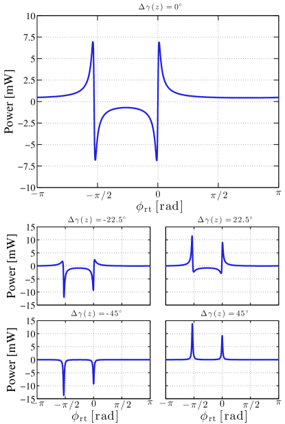
describes the ‘flavour’ of the cavity mismatch. For pure waist position (size) mismatches this quantity is (0 or ). By controlling the Gouy phase, , either through simple propagation or the construction of an appropriate telescope, the influence of this and the remaining terms may be removed to yield a quantity proportional to – a bi-polar function, centred about cavity resonance, which is ideal for use as an error signal in a feedback control system.
In order to isolate the error signal, care must be taken over the choice of photodiode geometry. Since we are examining interference between orthogonal modes, detection over a conventional single-element photodiode will yield no signal, i.e. .
The orthogonality of the interfering modes may be circumvented by any photodiode which does not sample all of the incident light. However, following the distribution of the electric field, a logical choice is to use a two-part, radially-split, bullseye photodiode (see Fig. 2, Path 1) and construct signals proportional to
| (8) |
by subtracting the outputs of the two segments.
Specifically, the error signal is maximised by taking , as this is the point where the electric field of changes sign, hence obviating any cancellation of signal. With this choice .
However, since the power on the two segments of the photodiode is not balanced, operating in this way can return impure error signals due to contamination by term (i) of (6). Hence, this mode of operation is best reserved for strongly overcoupled, high-finesse cavities.
For more general cavity configurations, this effect is easily mitigated by setting to balance the power on each photodiode segment. In this case , representing only a 6% loss of signal.
Removing the influence of variations in power necessarily dictates that changes in power are discernible. In particular, the tail of the resonance can cause small error signal offsets at the lock point. Again, such offsets are negligible so long as the and resonances do not overlap significantly. For example, using the parameters given in Fig. 3, this effect produces an offset which reduces circulating power by 5 ppm.
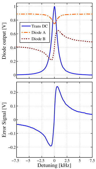
Although bullseye photodiodes are available they are by no means commonplace. Hence, we now introduce an alternative means of implementing our scheme (see Fig. 2 Path 2). Error signals obtained using this implementation are shown in Fig. 3.
The light reflected from the optical cavity is divided at a beamsplitter and relayed to two standard single-element photodiodes. Photodiode A captures the entire cross-section of the reflected beam, and is therefore sensitive to term (i), allowing us to subtract the contribution of the resonance dip from our error signal.
The beam propagating towards Photodiode B is clipped significantly by an adjustable iris. Thus, Photodiode B plays the role of the central part of a bullseye photodiode and is sensitive to term (iii).
The final error signal for use in a feedback control or measurement system is of the form , where the constant is chosen to null sensitivity to term (i) and depends on photodiode responsivities and transimpedance gains. For matched photodiodes, .
The Gouy phase and spot size at a bullseye detector are interdependent. The use of an adjustable iris as the effective clipping aperture eliminates this difficulty, with the Gouy phase at the iris now defining the relative phase of the interfering spatial modes. This phase is easily controlled by placing a waist-forming lens upstream of the aperture such that the beam explores a wide range of Gouy phases over a reasonable propagation distance. Modifying the position and radius of the aperture independently, one quickly approaches the optimal configuration given by, assuming , and, as before, . The lower axes of Fig. 3 illustrate the signals one might observe during this tuning process. The accuracy with which the optimal configuration can be achieved in practice could require further examination if this technique were to be used in exacting applications such as metrological standards.
Using two conventional photodiodes removes the need for specialised hardware at the expense of sensitivity. Since we do not detect all of the light, our signal is reduced by 50% with respect to optimal detection on a bullseye photodiode.
To validate our theoretical analysis, we applied the two-photodiode version of our scheme to a high-finesse optical cavity. The technique was found to be extremely robust against errors in iris radius and placement. Experimental data are shown in Fig. 4. Future practical investigations should explore the long-term stability of this method.
A comparable technique, relying on an mode [4] as the phase reference, has been developed previously [6]. Although this alternative offers an 8% improvement in theoretical sensitivity, we believe that the scheme described herein is superior for a number of reasons.
Foremost amongst these its insensitivity to beam jitter in reflection of the cavity. Odd-order-mode techniques are linearly sensitive to beam motion. This dependency can be mitigated but not without increasing the complexity of the scheme (‘double-pass tilt locking’), somewhat limiting its appeal. In contrast the sensitivity for even-order-mode techniques, such as ours, is quadratic. To appreciate this consider that, for the circularly symmetric modes under discussion, the power transmitted through an iris decreases with relative beam-iris motion, independent of the direction of the motion.
Our scheme does introduce a new sensitivity to beam spot size changes. However, such changes are rare and occur on thermal timescales whereas alignment fluctuations are common and exist over a wide range of frequencies.
Odd modes are excited by cavity misalignment while even modes arise due to mode mismatch. In general, achieving excellent cavity alignment is undemanding while attaining equivalent mode-matching efficiency requires extraordinary measures [9]. Therefore, pre-existing second-order modes suitable for use as a locking reference are almost invariably present, even after a system has been finely adjusted, and do not need to be purposely introduced. In contrast, exciting an additional reference mode requires that the cavity be intentionally misaligned, establishing noise coupling pathways and reducing shot-noise limited performance.
We have presented the analysis of an alternative means of locking a laser to a resonant optical cavity. This technique offers the possibility of shot-noise-limited performance whilst remaining uncomplicated and low-cost. Experimental investigation has confirmed our theoretical calculations and shown the technique to be simple to apply and robust against errors in implementation.
The authors gratefully acknowledge the support of the National Science Foundation and the LIGO Laboratory, operating under cooperative Agreement No. PHY-0757058. They also acknowledge Tomoki Isogai, Patrick Kwee and Lisa Barsotti for their roles in developing the apparatus on which the experimental portion of this work was performed. This paper has been assigned LIGO Document No. LIGO-LIGO-P1300209.
References
- [1] R. A. Boyd, J. L. Bliss, and K. G. Libbrecht, American Journal of Physics 64, 1109 (1996).
- [2] T. Hansch and B. Couillaud, Opt. Commun. 35, 441 (1980).
- [3] P. Asenbaum and M. Arndt, Opt. Lett. 36, 3720 (2011).
- [4] A. E. Siegman, Lasers (University Science Books, 1986).
- [5] C. E. Wieman and S. L. Gilbert, Opt. Lett. 7, 480 (1982).
- [6] D. A. Shaddock, M. B. Gray, and D. E. McClelland, Opt. Lett. 24, 1499 (1999).
- [7] D. Z. Anderson, App. Opt. 23, 2944 (1984).
- [8] E. Morrison, D. I. Robertson, H. Ward, and B. J. Meers, App. Opt. 33, 5041 (1994).
- [9] G. Mueller, Q.-Z. Shu, R. Adhikari, D. B. Tanner, D. Reitze, D. Sigg, N. Mavalvala, and J. Camp, Opt. Lett. 25, 266 (2000).
Informational Fifth Page
References
- [1] R. A. Boyd, J. L. Bliss, and K. G. Libbrecht, “Teaching physics with 670-nm diode lasers-experiments with Fabry-Perot cavities,” American Journal of Physics 64, 1109–1116 (1996).
- [2] T. Hansch and B. Couillaud, “Laser frequency stabilization by polarization spectroscopy of a reflecting reference cavity,” Opt. Commun. 35, 441 – 444 (1980).
- [3] P. Asenbaum and M. Arndt, “Cavity stabilization using the weak intrinsic birefringence of dielectric mirrors,” Opt. Lett. 36, 3720 (2011).
- [4] A. E. Siegman, Lasers (University Science Books, 1986).
- [5] C. E. Wieman and S. L. Gilbert, “Laser-frequency stabilization using mode interference from a reflecting reference interferometer,” Optics Letters 7, 480–482 (1982).
- [6] D. A. Shaddock, M. B. Gray, and D. E. McClelland, “Frequency locking a laser to an optical cavity by use of spatial mode interference,” Opt. Lett. 24, 1499–1501 (1999).
- [7] D. Z. Anderson, “Alignment of resonant optical cavities,” App. Opt. 23, 2944–2949 (1984).
- [8] E. Morrison, D. I. Robertson, H. Ward, and B. J. Meers, “Automatic alignment of optical interferometers,” App. Opt. 33, 5041–5049 (1994).
- [9] G. Mueller, Q.-Z. Shu, R. Adhikari, D. B. Tanner, D. Reitze, D. Sigg, N. Mavalvala, and J. Camp, “Determination and optimization of mode matching into optical cavities by heterodyne detection,” Opt. Lett. 25, 266–268 (2000).