Vortex arrays in a rotating superfluid 4He nanocylinder
Abstract
Within Density Functional theory, we investigate stationary many-vortex structures in a rotating 4He nanocylinder at zero temperature. We compute the stability diagram and compare our results with the classical model of vortical lines in an inviscid and incompressible fluid. Scaling the results to millimeter-size buckets, they can be compared with experiments on vortex arrays conducted in the past. Motivated by recent experiments that have used atomic impurities as a means of visualizing vortices in superfluid 4He droplets, we have also considered the formation of chains of xenon atoms along a vortex line and the interaction between xenon atoms inside the same vortex and on different neighboring vortex lines.
pacs:
67.25.D-, 67.25.dkI Introduction
At temperatures low enough, 4He droplets and confined clouds of ultra-cold boson gases are paradigms of superfluid quantum droplets. Small para-hydrogen clusters are likely superfluid,Gre00 although no definite conclusion has been experimentally drawn yet.Zen14 Together with the frictionless displacement of impurities at velocities below the Landau critical velocity,Pit03 the appearance of quantized vortices is the recognized hallmark of superfluidity in liquid 4He Fey55 ; Vin61 that appear at temperatures below 2.17 K, the superfluid transition temperature.
Due to its superfluid character, 4He remains at rest when its container rotates until a critical angular velocity is reached, leading to the appearance of vortices with quantized velocity circulation in units of , where is the Planck constant and is the 4He atomic mass. Free –or attached to impurities– linear vortices have been theoretically studied using methods of different complexity, see Refs. Dal92, ; Ort95, ; Gio96, ; Pi07, ; Gal14, ; Sad97, and references therein. In the case of cold gases, vortices have been nucleated using methods such as the rotation of the magnetic trap or the thermal cloud during the evaporative cooling process.Pit03 ; Fet09 These methods bear some similarity with the “rotating bucket” way of nucleating vortices in superfluid liquid helium.And46b
While vortex arrays in cold gases can be optically identified after the condensate has expanded upon removing the magnetic or optical trap, vortex distributions in liquid helium have been only visualized by doping them. They were first imaged by Packard and co-workersWil74 ; Yar79 with the spots of light on a phosphorescent screen caused by the hitting of electrons originally attached to vortex lines. More recently, quantized vortices have been visualized by suspending micron-sized solid particles of hydrogen in superfluid 4He at relatively high temperatures K,Zha05 ; Bew06 where they are found to arrange themselves with nearly equal spacing along vortex lines, or at lower temperatures K by He through excimers created in situ by ionization in a strong laser field.Zme13 Coalescence of gold nano-clusters inside vortices in superfluid 4He has been observedMor10 and further discussed in Ref. Gor12, .
The equilibrium configurations of vortex arrays in rotating superfluid helium were computed in Refs. Hes67, ; Sta68, ; Cam79, within the classical vortex theory of an inviscid and incompressible fluid that incorporates the quantum effect of quantization of circulation around vortex lines. A comprehensive review of the activity on quantized vortices in superfluid liquid helium before the 1990s can be found in the book by Donnelly.Don91
With the advent of helium droplet experimental facilities in the 1990s,Toe04 the issue whether nanodroplets are superfluid or not became a subject of intense experimental and theoretical activity.Sin89 ; Ram90 ; Chi92 ; Kro01 Helium droplets are created by expanding a cold helium gas and attain a limiting temperature below 0.4 K,Bri90 ; Har95 lower than the superfluid transition temperature. The experimental confirmation of superfluidity in helium droplets was provided by Toennies and coworkers, who established that an OCS molecule inside a 4He droplet displays a neat ro-vibrational spectrum, indicating that the molecule may rotate without dissipation, at variance with its behavior in a normal-fluid 3He droplet.Gre98 It is worth mentioning that the minimum number of atoms in the droplet for displaying superfluid features is amazingly small, about 60 atoms.
Several theoretical studies have been conducted for a single linear vortex in helium droplets taking for granted that they could be nucleated inside them.Bau95 ; Dal00 ; Anc03 ; Leh03 ; Sol07 Experimentally, the appearance of quantum vorticesGom12 ; Spe14 ; Lat14 ; Tha14 and the frictionless displacement of swift impurities in helium dropletsBra13 ; Mat13 have been recently established. In both cases, foreign atoms were used as tracers or swift impurities. The motion of tracer particles in superfluid 4He has been addressed in a number of papers, see for instance Refs. Poo05, ; Bar07, ; Fie12, and references therein.
Quantized ring vortices have been theoretically predicted to accompany the sinking of cations produced by photoionization of the neutral species sitting at the surface of 4He droplets under very well controlled experimental conditions.Mat14 Their effect on physical observables that might allow to experimentally detect them remains inconclusive yet.
Very recently, in a femtosecond X-ray coherent diffractive imaging experiment the existence of vortex arrays has been demonstrated for helium droplets.gom14 The diffraction images revealed characteristic Bragg patterns from Xe clusters trapped in the vortex cores present in the helium droplets made of helium atoms produced by fragmentation of a cryogenic fluid.
Theoretically addressing vortex arrays in helium droplets is a challenge irrespective of the method one uses. It is currently beyond the capabilities of quantum Monte Carlo methods that even for one single vortex yield different results depending on whether the fixed node or the fixed phase approximation is used.Ort95 ; Gio96 ; Gal14 To determine the equilibrium configuration of a vortex array within the classical vortex theory of an inviscid and incompressible fluid, it has to be imposed as a boundary condition that the vortex lines perpendicularly hit the droplet surface, which is not a trivial issue.Bau95 ; Leh03 This condition is built-in within the density functional theory (DFT) approach,Anc03 ; Pi07 that however has as a practical limitation the computing time needed to determine the structure of large enough droplets capable to host many vortex lines, thus hampering any systematic study of their appearance as a function of the rotating angular velocity.
As a first step towards a DFT description of vortex arrays in helium droplets we present here the simpler case of vortex arrays in a rotating self-bound 4He nanocylinder infinitely extended along the axial direction. On the one hand, it will allow to assess the applicability of the DFT method to vortex array configurations and on the other hand to address the cylindric configuration attained in rotating bucket experiments, for whose description only the classical vortex theory of an inviscid and incompressible fluid has been used in the past.Hes67 ; Sta68 ; Cam79 We complement this study determining for some cases of study, the structure of vortices doped with Xe atoms because of their relevance to recent experimental studies of vortex arrays in superfluid 4He nanodroplets.Gom14
II Model
We consider a self-bound superfluid 4He cylinder rotating around its symmetry -axis with a constant angular velocity . We assume in our calculation a uniform density along the -direction, which implies that the resulting vortices always remain rectilinear and that (for undoped vortices) the system is actually 2D. A complex wave function represents the superfluid helium state, with atomic density . To investigate the emergence of vortex structures in this system, we look for solutions of the time-dependent density functional equation in a rotating frame-of-reference with constant angular velocity (co-rotationg frame):
| (1) |
where is the -component of the orbital angular momentum operator. In the above equation, is the DFT Hamiltonian resulting from the functional variation of the energy density functional of Ref. Dal95, , modified to handle highly inhomogeneous helium density profiles as those appearing e.g. around very attractive impurities.Anc05 More specifically,
| (2) |
where is the potential energy density per unit volume.Dal95 ; Anc05 We have not included the velocity-dependent backflow term because it is ill-behaved at low densities. Although this is expected to impact the dynamics of vortex creation/evolution, this approximation cannot affect much the results in the present case where the stationary states and their relative energies are considered.
Rather than nucleating vortices in the cylinder by letting it rotate in real-time according to Eq. (1), we follow a more efficient strategy looking for stationary solutions in the co-rotating frame, , where the chemical potential and the time-independent effective helium wave function are obtained by solving the time-independent version of Eq. (1)
| (3) |
To determine describing a configuration where vortex lines are present we follow the “imprinting” strategy, i.e. we start the imaginary-time evolution of Eq. (3) leading to the minimum energy configuration with a helium wave functionPi07
| (4) |
where is the density of the vortex-free configuration and is the initial position of the -vortex core with respect to the axis of the cylinder. We remark that during the functional minimization the vortex coordinates will change to provide, at convergence, the lowest energy vortex configuration; we also define as the radial position of the -th vortex. Details on how Eq. (3) has been solved can be found in Ref. Her07, . Both the density and wave function have been discretized in cartesian coordinates using a spatial grid fine enough to guarantee well converged results. The spatial derivatives have been calculated with 13-point formulas. Fast-Fourier techniquesFri05 have been employed to efficiently calculate the energy density and mean-field potential.
Within DFT approximation the vorticity field has a singularity along one or several lines, the vortex cores, where the density vanishes and the velocity diverges. The helium density around one such vortex line is shown in Fig. 1. In accordance with previous studies, the vortex structure is characterized by a core region of size Å.
III Results
III.1 Undoped vortices

By using the imprinting method described above, for a given angular velocity we have computed a number of lowest energy configurations with a fixed number of vortices . If more than one configuration is obtained with the same –depending on the initial guess for the vortex distribution embodied in Eq. (4)– we choose the one with lower total energy.
The configurations of a vortex array in a rotating cylinder can be completely characterized,Hes67 within the Onsager-Feynman model, by the dimensionless free energy per unit length (that at zero temperature coincides with the energy per unit length), the dimensionless angular velocity and the scaled radial positions of the vortices , where Å-3 is the atom density of liquid 4He and the cylinder radius. We will use these units in the following, thus making easier to compare our results, obtained for a system of nanoscopic size, with experimental results characterized by much larger values of and much smaller values of .
We show in Fig. 2 a few stationary configurations with to . The radius of the nanocylinder at rest is Å. It has been chosen rather arbitrarily as a compromise between numerical affordability and the need of disposing of a “nanobucket” that could host many vortex lines.
The stability diagram is shown in Fig. 3, where the energy per unit vortex length in the co-rotating frame, i.e. , is shown as a function of the dimensionless angular velocity for up to . The crosses between the different lines, indicated by upside down triangles, yield the critical rotational velocities for -vortex nucleation.
Within each stability region, the calculated energies show an almost linear behavior with . This behavior is strictly linear for =1, as the centered single vortex state is an eigenstate of the total angular momentum. For other values this is not so and bends. However, this happens outside the corresponding stability region. As a consequence, the average slope of each stability region in Fig. 3 changed of sign does represent the total angular momentum per unit length. DFT yields for , being the number of helium atoms in the cylinder per unit length, a value of 1 for , and of 7.081 for . It is possible to use linear response theory around the equilibrium configurations corresponding to each value to determine the moment of inertia per unit length around the symmetry axis of the cylinder .Zen14 ; Lip03 However, the mentioned linear behavior of allows one to obtain in a much simpler way, writing within each stability region . displays a step-like behavior as a function of , being zero in absence of vortices.
It is illustrative to compare the DFT results with those obtained using the classical vortex theory of inviscid and incompressible fluids.Hes67 It turns out that both yield results in agreement with each other. In particular, the DFT values for the total angular momentum per unit length expressed in reduced units, , are very close to the classical theory ones given by the expressionHes67 , where is the distance of the -th vortex from the rotation axis. Indeed, for the values of shown in Fig. 3 they agree to within .
However, a larger discrepancy is found for the critical rotation velocity for the nucleation of a single vortex that within the classical vortex theory is given byDon91
| (5) |
hence . Using our system values for and the above equation yields , whereas the DFT value, given by the intersection of the line in Fig. 3 with the horizontal line representing the vortex-free energy, is . There would be needed much smaller a vortex core value ( Å) to reconcile the classical theory with the DFT results.
In the case of two linear vortices symmetrically placed with respect to the axis of the cylinder, the energy of the pair as computed from the classical theory isHes67
| (6) |
where with being the vortex-vortex distance. The equilibrium condition yields
| (7) |
which admits a solution as long as .
We plot in Fig. 4 the calculated vortex-vortex equilibrium distance for the two-vortex array as a function of the angular velocity and compare it with the value obtained from Eq. (7). The agreement is good at low , up to the limiting value (which is the lowest displayed value with the solid line). At high values of the DFT results level off. This is due to the superposition of the core structures which prevents further decrease in the distance, and the classical vortex theory does not hold because of the inhomogeneities in the density profile, shown in the inset of Fig. 4, where the vortex structure at closest approach is displayed. For angular velocities larger than those displayed in the figure with open squares, the whole 4He cylinder becomes unstable and the DFT minimization procedure fails.
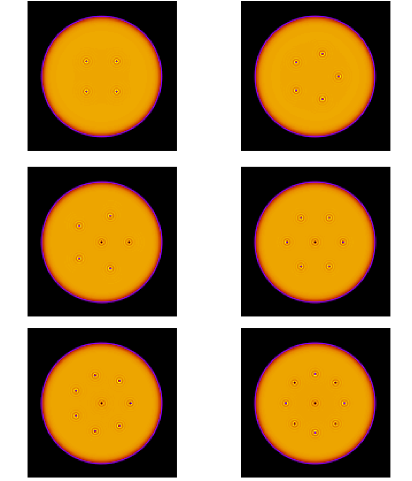

As for the equilibrium structures, the DFT results are in agreement with those of the classical vortex theoryCam79 for a rotating cylinder of superfluid 4He. The energetically favored structures for are made of rings of vortices plus one vortex at the center of the cylinder. The tendency of rings of vortices to form was observed long ago in a rotating bucket experiment.Yar79 Our findings are consistent with this observation and with other fine details. In particular, for besides the stable five-fold ring of vortices plus a vortex at the center, a metastable state made of a six vortex ring is experimentally observed; in our calculations this state is almost degenerate with the stable one. Both configurations were also found within the classical vortex theory,Cam79 but with the six-vortex ring fairly higher in energy than the stable state.

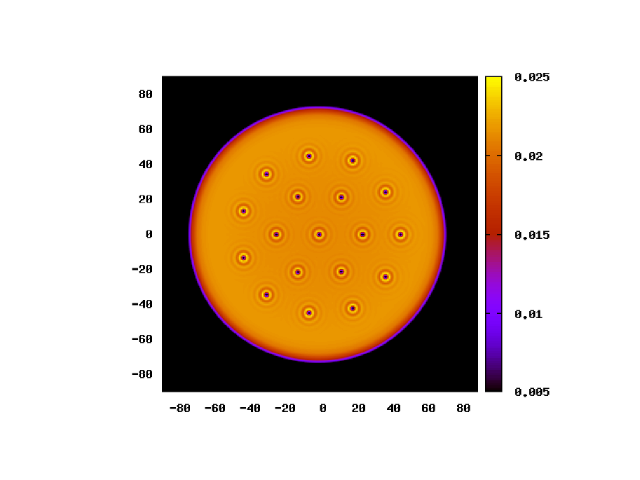
A configuration with a larger number of vortices, namely , is shown in Fig. 5. This equilibrium vortex structure again coincides with the lowest energy structure of classical vortex theory.Cam78 Within such theory, the areal density of vortex lines is proportional to the angular velocity, .Fey55 ; Sta68 Assuming a triangular distribution for the vortex lines, the areal density would be , where is the mean inter-vortex distance. By equating these two expression for , with the value used to obtain the distribution shown in Fig. 5 one gets . From Fig. 5 one can estimate an average vortex-vortex distance Å, i.e. , which compares well with the result of the classical vortex theory.
We remark at this point that the scaled lengths and frequencies and which characterize the vortex array configurationsHes67 allow to compare the results for a nanoscopic system, like the ones presented here, to the actual experiments where typical lengths and frequencies differ by many orders of magnitude. This is proven, for instance, by looking at the rotating bucket experimental results of Ref. Yar79, . Figure 2(e) in this reference shows the 5-fold ring of vortices nucleated in a rotating bucket of radius mm with angular velocity . The average scaled distance between neighboring vortex cores can be read directly from that figure, . From our DFT calculations for a 5-fold ring of vortices at the same value of the dimensionless frequency in a nanobucket with Å we get a ratio which is compatible with the experimental one.
III.2 Doped vortices
We next study the changes in the vortex structures induced by the capture of atomic impurities inside the vortex cores. We consider the particular case of Xe atoms because of their use as vortex tracers in recent experiments.Gom14 Due to the large mass of the Xe atom as compared to that of the He atom, their effect on the liquid is incorporated through an external potential (which is taken from Ref. Tan03, ), i.e. in Eq. (2) is replaced by , where is the position of the -th Xe atom.
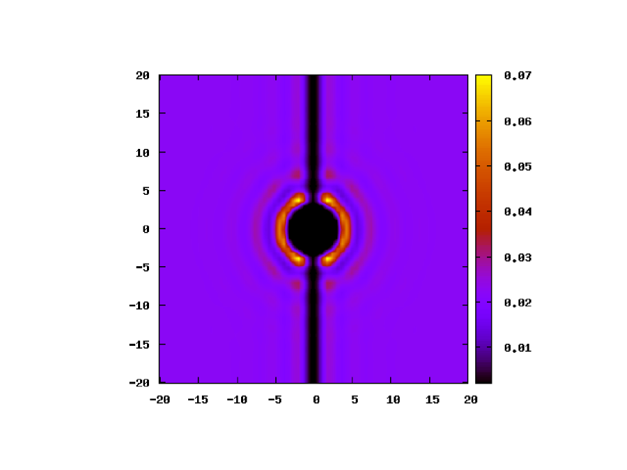
The equilibrium density profile around a Xe impurity trapped inside a vortex core is shown in Fig. 6. Due to the periodic boundary conditions inherent to the use of the Fast-Fourier method,Fri05 this configuration actually corresponds to a linear chain of Xe atoms separated one-another by a distance equal to the length of the simulation cell along the vortex axis, which in the present case is 30 Å. Since the Xe distance between periodically repeated images is so large, the interaction between images can be safely neglected and in practice that configuration representis indeed an isolated Xe atom attached to the vortex. We have calculated the binding energy of the Xe atom to the vortex line asPi07
| (8) |
where , , , and are the energies of the (vortex+Xe), (Xe), (vortex) and pure 4He cylinder, respectively. We have found K, which compares favorably with earlier estimates,Dal00 where a value close to K was found using a different functional. The positive value of implies that the Xe impurity is energetically stabilized inside the vortex line.

We have also computed the energy of two Xe atoms within the same vortex line as a function of the Xe-Xe distance. To model the Xe-Xe interaction we have used the pair potential function computed in Ref. Tan03, . The results are shown in Fig. 7, where the energy difference with respect to the configuration of two Xe atoms well apart from each other is shown as a function of the atoms separation. As was also found for other impurities, Pop13 the Xe atoms are free to move along the vortex line, and the lowest energy state is the one where the Xe atoms have formed a dimer, whose bond length almost coincide with that of the Xe dimer in vacuum.
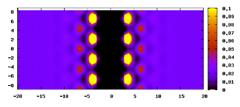
Additional Xe atoms trapped within the same vortex line can in principle form a one-dimensional atomic chain completely filling the vortex core. The structure of such Xe chain is shown in Fig. 8. The helium density close to the Xe atoms appear to be rather structured, with values that locally exceed the bulk density by a factor of 2-3. It was experimentally found that the atomic impurities are trapped in vortex lines in the form of regularly spaced atomic clusters, rather than forming atomic chains.Gom12 ; Spe14 ; Lat14 ; Tha14 Actually, the relatively large size of such clusters allow to use them to effectively image the vortex itself.Gom14
While being certainly interesting because of its relevance to the experimental studies of the elusive vortices in superfluid 4He nanodroplets, the theoretical study of atomic clusters in vortex lines is beyond the scope of this paper. We rather address briefly here the simpler case of a vortex line filled with Xe atomic chain. Albeit being aware of its limitations, we believe nevertheless that it might be a useful first attempt to address the rather complex issue of impurity aggregates inside vortex arrays. It is worth mentioning that cluster merging inside the same vortex line may be hampered by the existence of energy barriers –to which the very structured helium density around impurities contribute in a non-negligible way– and that there are experimentalPrz08 ; Log11 and theoreticalElo08 ; Her08 examples of metastable structures made of nearly isolated impurities or impurity clusters coexisting in helium droplets. The specific characteristics of the formation of atomic clusters in helium droplets haven been reviewed in Ref. Tig07, .
By completely filling the core of a single vortex with a chain of Xe atoms at the dimer equilibrium distance, the liquid helium is expelled from the region around the axis of the cylinder constituting an annulus of inner radius about that of the Xe-He pair-potential core that replaces the vortex line. An annular geometry was used by Vinen in his classical experiment on quantized circulation,Vin61 showing that above a certain angular velocity a quantized circulation of the superfluid velocity appeared around the axis of the annulus, and that increasing further the angular velocity vortices could appear. Low-lying states of rotating superfluid 4He in an annulus were studied by Stauffer and FetterSta68 with the classical inviscid fluid model finding that the vortices lie on a ring midway between the boundaries of the annulus. The number of vortices in the ring increases with increasing angular velocity, with the possibility of forming more than one ring. The same phenomenology appears in DFT simulations, as shown in Fig. 9, where we show the calculated structure with a 5-vortex ring enclosing the annulus in the center formed by a Xe-filled central vortex line.
The filling of neighboring vortex lines with atomic impurities/clusters is likely having observable effects on the vortex distribution in a multi-vortex configuration, like the ones recently observed in 4He nanodroplets. Gom14 As a first step towards understanding the effect of cluster doping on a vortex array, we consider here the interaction between a pair of doped vortices, similarly to what done for the “empty” vortex pair, but with the cores completely filled by a chain of Xe atoms. Any effect should show up in changes of the vortex mutual distance as a function of the rotational frequency, as compared to the case of empty vortices. The results of our calculations are shown in Fig. 4 with filled squares. It appears that there is no evident change in the vortex-vortex distance induced by the Xe adsorption (apart when the two vortex cores are very close to one another), in spite of the additional rotational energy due to the Xe mass ( being the Xe mass per unit vortex length) rotating with the vortex pair. Although such contribution is small in the present case, due to the nanoscopic dimension of our system, it could become relevant in experimental situation, altering the distribution of vortex lines containing Xe clusters, especially at the periphery of the droplet. Such effect seems to have been observed in the experimental images of Ref. Gom14, .

IV Summary and outlook
Within the zero temperature Density Functional approach, we have studied the formation of vortex arrays in a rotating 4He cylinder of nanoscopic dimension. We have found that the simple scaling relations that characterize the classical theory of quantized vortices in incompressible and inviscid fluid can be used to determine, starting from the nanoscale DFT results presented here, the structure of vortex arrays in the millimeter-sized samples used in rotating bucket experiments.
Motivated by current experiments on 4He nanodroplets, we have also addressed the effect of doping the vortex cores with Xe impurities. Somewhat unexpectedly, we have found that adding these impurities does not introduce sensible changes in the inter-vortex distance. Since such changes has been experimentally observed at the periphery of droplets,Gom14 there remains to be seen whether they are due to the role played by the geometry: unlike the case of an infinitely extended cylinder, in a spherical drop quite some Xe atoms/clusters are located not far from its curved surface where the vortex cores are wider and the helium density lower. We are currently undertaking the study of vortex arrays within 4He nanodroplets, which will be the subject of a forthcoming work.
Acknowledgements.
We thank Andrei Vilesov, Jesús Navarro and Andrew Ellis for stimulating discussions. This work has been performed under Grants No. FIS2011-28617-C02-01 from DGI, Spain (FEDER) and 2014SGR401 from Generalitat de Catalunya.References
- (1) S. Grebenev, B. Sartakov, J.P. Toennies, and A. Vilesov, Science 289, 1532 (2000).
- (2) T. Zeng and P.-N. Roy, Rep. Prog. Phys. 77, 046601 (2014).
- (3) L. Pitaevskii and S. Stringari, Bose-Einstein Condensation, International Series of Monographs on Physics 116 (Clarendon Press, Oxford 2003).
- (4) R.P. Feynman, Progress in Low Temperature Physics, C.J. Gorter, Editor (North-Holland Publishing Company, Amsterdam 1955), vol. 1, p. 1.
- (5) W.F. Vinen, Proc. Roy. Soc. A 260, 218 (1961).
- (6) F. Dalfovo, Phys. Rev. B 46, 5482 (1992).
- (7) G. Ortiz and D.M. Ceperley, Phys. Rev. Lett. 75, 4642 (1995).
- (8) S. Giorgini, J. Boronat, and J. Casulleras, Phys. Rev. Lett. 77, 2754 (1996).
- (9) M. Sadd, G.V. Chester, and L. Reatto, Phys. Rev. Lett. 79, 2490 (1997).
- (10) D.E. Galli, L. Reatto, and M. Rossi, Phys. Rev. B 89, 224516 (2014).
- (11) M. Pi, R. Mayol, A. Hernando, M. Barranco, and F. Ancilotto, J. Chem. Phys. 126, 244502 (2007).
- (12) A.L. Fetter, Rev. Mod. Phys. 81, 647 (2009).
- (13) E.L. Andronikashvili, J. Phys. USSR 10, 201 (1946).
- (14) G.A. Williams and R.E. Packard, Phys. Rev. Lett. 33, 280 (1974).
- (15) E.J. Yarmchuk, M.J.V. Gordon, and R.E. Packard, Phys. Rev. Lett. 43, 214 (1979).
- (16) T. Zhang and S. W. Van Sciver, Nature Physics 1, 36 (2005)
- (17) G.P. Bewley, D.P. Lathrop, and K.R. Sreenivasan, Nature 441, 588 (2006).
- (18) D.E. Zmeev, F. Pakpour, P.M. Walmsley, A.I. Golov, W. Guo, D.N. McKinsey, G.G. Ihas, P.V.E. McClintock, S.N. Fisher, and W.F. Vinen, Phys. Rev. Lett. 110, 175303 (2013).
- (19) P. Moroshkin, V. Lebedev, B. Grobety, C. Neururer, E.B. Gordon, and A. Weis, Eur. Phys. Lett. 90, 34002 (2010).
- (20) E.B. Gordon, A.V. Karabulin, V.I. Matyushenko, V.D. Sizov, and I.I. Khodos, Chem. Phys. Lett. 519-520, 64 (2012).
- (21) G.B. Hess, Phys. Rev. 161, 189 (1967).
- (22) D. Stauffer and A.L. Fetter, Phys. Rev. 168, 156 (1968).
- (23) L.J. Campbell and R.M. Ziff, Phys. Rev. B 20, 1886 (1979).
- (24) R.J. Donnelly, Quantized vortices in helium II, Cambridge Studies in Low Temperature Physics (Cambride University Press, Cambridge, U.K. 1991), Vol. 3.
- (25) J.P. Toennies and A.F. Vilesov, Angew. Chem. Int. Ed. 43, 2622 (2004).
- (26) P. Sindzingre, M.L. Klein, and D.M. Ceperley, Phys. Rev. Lett. 63, 1601 (1989).
- (27) M.V. Rama Krishna and K.B. Whaley, Phys. Rev. Lett. 64, 1126 (1990).
- (28) S.A. Chin and E. Krotscheck, Phys. Rev. B 45, 852 (1992).
- (29) E. Krotscheck and R. Zillich, J. Chem. Phys. 115, 1016 (2001).
- (30) D.M. Brink and S. Stringari, Z. Phys. D 15, 257 (1990).
- (31) M. Hartmann, R.E. Miller, J. P. Toennies, and A. Vilesov, Phys. Rev. Lett. 75, 1566 (1995).
- (32) S. Grebenev, J.P. Toennies, and A. Vilesov, Science 279, 2083 (1998).
- (33) G.H. Bauer, R.J. Donnelly, and W.F. Vinen, J. Low Temp. Phys. 98, 47 (1995).
- (34) F. Dalfovo, R. Mayol, M. Pi, and M. Barranco, Phys. Rev. Lett 85, 1028 (2000).
- (35) K.K. Lehmann and R. Schmied, Phys. Rev. B 68, 224520 (2003).
- (36) F. Ancilotto, M. Barranco, and M. Pi, Phys. Rev. Lett. 91, 105302 (2003).
- (37) E. Sola, J. Casulleras, and J. Boronat, Phys. Rev. B 76, 052507 (2007).
- (38) L.F. Gomez, E. Loginov, and A.F. Vilesov, Phys. Rev. Lett. 108, 155302 (2012).
- (39) D. Spence, E. Latimer, C. Feng, A. Boatwright, A.M. Ellis, and S. Yang, Phys. Chem. Chem. Phys. 16, 6903 (2014).
- (40) E. Latimer, D. Spence, C. Feng, A. Boatwright, A.M. Ellis, and S. Yang, Nano Lett. 14, 2902 (2014).
- (41) Ph. Thaler, A. Volk, F. Lackner, J. Steurer, D. Knez, W. Grogger, F. Hofer, and W.E. Ernst, Phys. Rev. B, to be published (2014).
- (42) N.B. Brauer, S. Smolarek, E. Loginov, D. Mateo, A. Hernando, M. Pi, M. Barranco, W.J. Buma, and M. Drabbels, Phys. Rev. Lett. 111, 153002 (2013).
- (43) D. Mateo, A. Hernando, M. Barranco, E. Loginov, M. Drabbels, and M. Pi, Phys. Chem. Chem. Phys. 15, 18388 (2013).
- (44) D.R. Poole, C.F. Barenghi,Y.A. Sergeev, and W.F. Vinen, Phys. Rev. B 71, 064514 (2005).
- (45) C. Barenghi, D. Kivotides, and Y. Sergeev, J. Low Temp. Phys. 148, 293 (2007).
- (46) S.L. Fiedler, D. Mateo, T. Aleksanyan, and J. Eloranta, Phys. Rev. B 86, 144522 (2012).
- (47) D. Mateo, A. Leal, A. Hernando, M. Barranco, M. Pi, F. Cargnoni, M. Mella, X. Zhang, and M. Drabbels, J. Chem. Phys. 140, 131101 (2014).
- (48) L.F. Gomez, K.R. Ferguson, J.P. Cryan, C. Bacellar, R. Mayro P. Tanyag, C. Jones, S. Schorb, D. Anielski, A. Belkacem, C. Bernando, R. Boll, J. Bozek, S. Carron, G. Chen, T. Delmas, L. Englert, S.W. Epp, B. Erk. L. Foucar, R. Hartmann, A. Hexemer, M. Huth, J. Kwok, S.R. Leone, J.H. S. Ma, F.R. N. C. Maia, E. Malmerberg, S. Marchesini, D.M. Neumark, B. Poon, J. Prell, D. Rolles, B. Rudek, A. Rudenko, M. Seifrid, K.R. Siefermann, F.P. Sturm, M. Swiggers, J. Ullrich, F. Weise, P. Zwart, C. Bostedt, O. Gessner, and A.F. Vilesov, Science 906, 6199 (2014).
- (49) F. Dalfovo, A. Lastri, L. Pricaupenko, S. Stringari, and J. Treiner, Phys. Rev. B 52, 1193 (1995).
- (50) F. Ancilotto, M. Barranco, F. Caupin, R. Mayol, and M. Pi, Phys. Rev. B 72, 214522 (2005).
- (51) A. Hernando, R. Mayol, M. Pi, M. Barranco, F. Ancilotto, O. Bünermann, and F. Stienkemeier, J. Phys. Chem. A 111, 7303 (2007).
- (52) M. Frigo and S.G. Johnson, Proc. IEEE 93, 216 (2005).
- (53) E. Lipparini, Modern Many Particle Physics-Atomic Gases, Quantum Dots and Quantum Fluids (2nd. edition, World Scientific, Singapore 2008).
- (54) L.J. Campbell and R.M. Ziff, Los Alamos Scientific Laboratory Report No. LA-7384-MS (1978).
- (55) K.T. Tang and J.P. Toennies, J. Chem. Phys. 118, 4976 (2003).
- (56) E. Popov, M. Mammetkuliyev, and J. Eloranta, J. Chem. Phys. 138, 204307 (2013).
- (57) A. Przystawik, S. Göde, T. Döppner, J. Tiggesbäumker, and K-H. Meiwes-Broer, Phys. Rev. A 78, 021202(R) (2008).
- (58) E. Loginov, L.F. Gomez, N. Chiang, A. Halder, N. Guggemos, V.V. Kresin, and A.F. Vilesov, Phys. Rev. Lett. 106, 233401 (2011).
- (59) J. Eloranta, Phys. Rev. B 77, 134301 (2008).
- (60) A. Hernando, M. Barranco, R. Mayol, M. Pi, and F. Ancilotto, Phys. Rev. B 78, 184515 (2008)
- (61) J. Tiggesbäumker and F. Stienkemeier, Phys. Chem. Chem. Phys. 9, 4748 (2007).