Scalability and Resilience of Software-Defined Networking: An Overview
Abstract
Software-Defined Networking (SDN) allows to control the available network resources by an intelligent and centralized authority in order to optimize traffic flows in a flexible manner. However, centralized control may face scalability issues when the network size or the number of traffic flows increases. Also, a centralized controller may form a single point of failure, thereby affecting the network resilience.
This article provides an overview of SDN that focuses on (1) scalability concerning the increased control overhead faced by a central controller, and (2) resiliency in terms of protection against controller failure, network topology failure and security in terms of malicious attacks.
I Introduction
Currently, most switching and routing solutions integrate both data and control plane functionality. The data plane performs per-packet forwarding based on look-up tables located in the memory or buffer of the switch or router, whereas the control plane is used to define rules based on networking policies to create the look-up tables. Due to the high demands on network performance and growing configuration complexity, the control plane has become overly complicated, inflexible and difficult to manage. To solve this problem a new networking paradigm was needed, which was compatible with the widely used Ethernet switching and IP routing techniques. The solution was found in virtualization techniques used in server applications, where an abstraction layer is positioned above the server hardware to allow multiple virtual machines to share the available resources of the server. Software Defined Networking (SDN) adopted this paradigm and introduced an abstraction layer in networking.
By abstracting the network resources, the data and control planes are separated. The data plane is located at the switch hardware, where the optimized forwarding hardware is preserved and the control of the network is centralized into an intelligent authority with the aim to improve flexibility and manageability. A centralized authority provides the intelligence to network switches to route and control the traffic through the network infrastructure. Optimal paths through the network can be provided by the central authority in advance or on demand. The current implementation of the SDN networking paradigm is found in the OpenFlow protocol developed by Stanford University in 2008 and is currently under development within the Open Networking Foundation. OpenFlow has attracted some big vendors in the networking community and became the most popular realization of the SDN networking paradigm.
Since the introduction of OpenFlow, much research has been performed on two different fields, being i) scalability and performance of the central authority in relation to the growth of network traffic and requests, and ii) the robustness and resiliency of the network against link and switch failures in the network, but also failures of the central authority. Clearly, the two are related, since scalability issues may cause failures.
In this overview, we specifically focus on scalability and resilience of SDN. In section II, we our work from existing surveys on SDN and OpenFlow networking. We describe the basics behind the SDN paradigm, the OpenFlow protocol, network controllers and compliant switches in section III. The general framework and standard notation is given in section IV, while sections V to VI discuss related work in relation to our framework. Section VII concludes this overview.
II Related Surveys
Nunes et al. [1] presented a standard survey with emphasis on past, present and future implementations of SDN. It gives a proper overview of possible applications that could benefit from SDN. Feamster et al. [2] give a historical insight in the development of SDN networks, with the emphasis on virtualizing the network and separating the data and control planes. A survey on security in SDN is given by Scot-Hayward et al. [3]. The survey provides a nice categorization on security-related research and addresses security analysis, enhancements and solutions, as well as the data, control and application layer of SDN. Yeganeh et al. [4] focus on the scalability concerns in relation to current-state networking, controllers and switching hardware. Sezer et al. [5] discus the implementation challenges for SDN in relation to carrier-grade networks. Suzuki et al. [6] take a similar approach concerning OpenFlow technologies in carrier-grade and data center networks. In [7], Lara et al. provide an extensive survey on network innovations using OpenFlow, where the OpenFlow specification is discussed in detail and recent experiences with OpenFlow deployments on campus networks and testbeds are shared.
In contrast to the above mentioned surveys, we propose a graphical reference framework, with which SDN strengths and frailties are identified more easily. Furthermore, we specifically focus on scalability and resilience aspects.
III Introduction to
Software-Defined Networking
In this section we introduce Software-Defined Networking (section III-A), the OpenFlow protocol (section III-B), OpenFlow controllers (section III-C) and Open vSwitch (section III-D).
III-A Abstracting the network
In the SDN philosophy, the network topology is configured based on requests from network services and applications. Services request connectivity to a network and if the request can be fulfilled, paths through the topology are provided to the service for the requested amount of time. In figure 1 the SDN concept is presented.
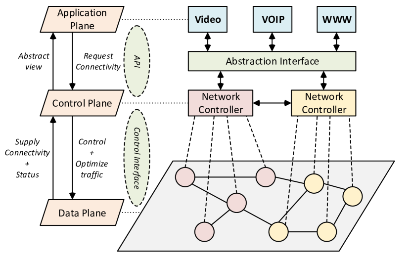
The SDN concept speaks of three planes, which do not correspond directly with the OSI reference model. A short description of the planes is given below:
-
•
Data Plane - The Data Plane is built up from Network Elements and provides connectivity. Network Elements consist of Ethernet switches, routers and firewalls, with the difference that the control logic does not make forwarding decisions autonomously on a local level. Configuration of the Network Elements is provided via the control interface with the Control Plane. To optimize network configuration, status updates from the elements are sent to a Network Controller;
-
•
Control Plane - Network Controllers configure the Network Elements with forwarding rules based on the requested performance from the applications and the network security policy. The controllers contain the forwarding logic, but can be enhanced with additional routing logic. Combined with actual status information from the Data Plane, the Control Plane can compute optimized forwarding configurations. To the application layer, an abstract view from the network is shared via a general Application Programming Interface (API). This abstract view does not contain details on individual links between elements, but enough information for the applications to request and maintain connectivity;
-
•
Application Plane - Applications request connectivity between two end-nodes, based on delay, throughput and availability descriptors received in the abstract view from the Control Plane. The advantage is the dynamic allocation of requests, as non-existing connectivity does not need processing at local switch level. Also applications can adapt service quality based on received statistics. For example to throttle the bandwidth for video streaming applications on high network utilization.
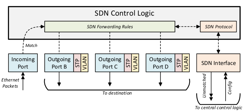
By decoupling the control logic the management of switches simplifies, as decisions to flood or forward data packets are not made locally anymore. Header information from data packets at the switches must be transmitted to the central control logic for processing and configuration computations, which introduces an additional delay in packet forwarding. As seen in figure 2, the basic functionality of the SDN switch is similar to that of an Ethernet switch. Header information is matched to the configured SDN Forwarding Rules and packets are subsequently forwarded to the configured outgoing port(s). Unmatched header information is sent to the central control logic via the SDN control interface. Thus, for communication between the SDN switch and the centralized controllers an additional protocol is needed. This protocol must contain the functionality to configure forwarding rules and ports, as well be able to collect and transmit switch status and statics to the central control logic. OpenFlow is such a protocol.
III-B OpenFlow protocol
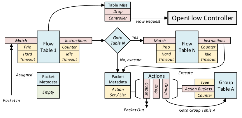
Two examples of SDN protocols are OpenFlow [8] and ForCES [9]. More protocols exist, however OpenFlow is most popular. OpenFlow has attracted many researchers, organizations and foundations, so a wide collection of open-source software is available in the form of OpenFlow controllers (section III-C), as well as physical and virtual switch implementations (section III-D). The OpenFlow protocol describes and couples switching hardware to software configurations, such as incoming and outgoing ports, as well as an implementation of the SDN Forwarding Rules. In figure 3 a flow diagram is given of the matching process of an incoming packet in an OpenFlow-compliant switch enabled with protocol version . A detailed survey on the OpenFlow specification is given in [7].
The SDN Forwarding Rules, called Flows in OpenFlow, are stored in one or more Flow Tables. For each incoming packet, a metadata set is created, containing an Action List, Action Set or both. In the Action List and Set actions are added for each Flow Table the packet transverses, whereas the Actions define the appropriate operations for the packet. Examples of Actions are forward the packet to port X, drop the packet, go to Group Table A or modify the packet header. The main difference between a List and Set is the time of execution. Actions added to a List are executed directly after leaving the current Flow Table, whereas the Actions defined in the Set are accumulated and executed when all Flow Tables are processed. Each Flow Table contains Flow Entries with six parameters [8]:
-
•
Match - The criteria to which the packets are matched. Criteria include parameters of the datalink, network and transport layers contained in data packet headers and optionally metadata from previous tables. A selection of criteria is given in table I;
-
•
Instructions - When a packet matches, instructions are added to the metadata set to direct the packet to another Flow Table or add Actions to the Action List or Set;
-
•
Priority - The packet header can match to multiple Flow Entries, but the entry with highest priority determines the operations;
-
•
Counter - Every time a packet has matched and is processed by a Flow Entry, a counter is updated. Counter statistics can be used by the OpenFlow controller and Application Plane to determine network policies or for network monitoring [10];
-
•
Hard Timeout - A Flow Entry is added by an OpenFlow controller, where the maximum amount of time this entry may exist in the Flow Table before expiring is defined by the Hard Timeout. The Hard Timeout can be used to limit network access for a certain node in the network and for automatic refreshing of the Flow Table to prevent large tables;
-
•
Idle Timeout - The amount of time a Flow Entry is not matched is defined as the idle time. Idle Timeout defines the maximum idle time and is mainly used for refreshing Flow Tables.
| Match Field | Layer | Description |
|---|---|---|
| Ingress Port | Physical | Incoming ports and interfaces |
| Ethernet Address | Datalink | Source and destination MAC-address |
| VLAN | Datalink | VLAN identity and priority |
| MPLS | Network | MPLS label and traffic class |
| IP | Network | IPv4 / IPv6 addresses |
| Transport | Transport | TCP/UPD, source and destination port |
From OpenFlow protocol version 1.1 and onwards, Group Tables have been defined. Group Tables allow more advanced configurations and consist of three parameters:
-
•
Action Buckets - Each bucket is coupled to a switch port and contains a set of Actions to execute. The main difference with Instructions from the Flow Table is that Action Buckets can be coupled to counters and interface status flags. Based on values of these parameters a bucket is valid or not;
-
•
Type - Defines the behavior and the number of Action Buckets in the Group Table. Multiple Action Buckets can be used for i) multicast and broadcast applications, where the incoming packet is copied over multiple Action Buckets (multiple ports), ii) load sharing applications, where a selection mechanism selects the Action Bucket to execute and iii) failover applications, where from the available Action Buckets the first live one is selected to execute. Assigning a single Action Bucket to a Group Table is useful for defining Actions for a large number of Flow Entries with the same required forwarding policy;
-
•
Counter - The number of times the Group Table has been addressed.
With the descriptions of the Flow and Group Table we can follow the incoming packet from figure 3. At entry, a metadata set is assigned to the data packet and the packet header is matched to the Flow Entries in the first Flow Table. On match, instructions are added to the Action Set and the packet can be processed further. When the instructions include forwarding to other Flow Tables, the packet with metadata is processed in a similar way and instructions are added to the Set. When no forwarding to other Flow Tables is instructed, the Action Set from the metadata is executed. Actions from the Set and / or Group Table determine the process of the packet. In switching operation, the MAC address is matched in the first Flow Table and the Action Set defines how to forward the packet on a specified outgoing port. When none of the Flow Entries match, a Table Miss is initiated. Depending on the configuration by the OpenFlow controller, the packet is dropped or transmitted to the controller for a Flow Request. At the controller, new Flow Entries are computed and added to Flow Tables of involved switches.
III-C OpenFlow Controller
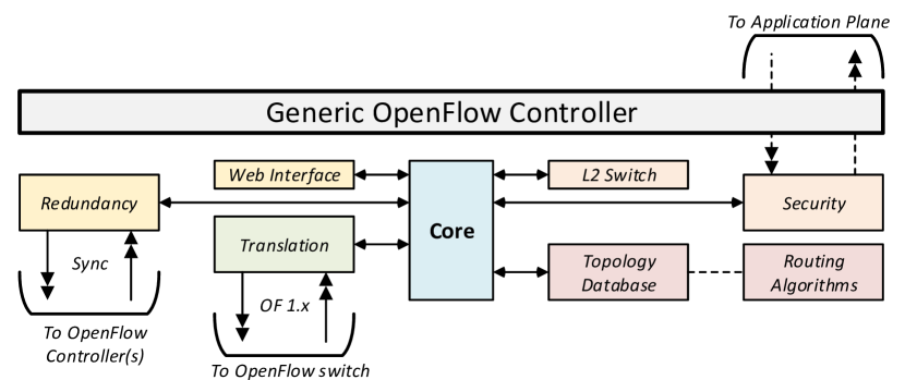
OpenFlow controllers are developed in many variations and all share the same goal of controlling and configuring compliant switches. In [1] and [7] a list of hardware switches is given, all OpenFlow compliant. Main differences are found in programming languages and support for OpenFlow specifications. Popular implementations, like NOX [11] and the Open vSwitch (OVS)-controller from Open vSwitch [12] use the C/C++ language, while POX [13] and Ryu [14] are Python-based controllers. Java based controllers are found in FloodLight [15] and OpenDayLight [16]. Only Ryu, OpenDayLight and unofficial ported versions from NOX support OpenFlow protocol version 1.3 so far. For more advanced configuration purposes and the use of Group Tables, we advise the Ryu and OpenDayLight controller. Both FloodLight and OpenDayLight offer web browser based configuration tools instead of command line interfaces and are therefore more user friendly. NOX, POX and Ryu share a similar structure and this shared structure is used to give an example of an OpenFlow controller in figure 4.
The example controller is built around a Core application, which acts as an backbone in the controller. To communicate with the OpenFlow switch, a translation module is added to translate OpenFlow protocol messages to controller parameters. Other modules, like a layer-2 switch module (L2-switch) in Ryu, can advertise themselves to the Core application and register on specific switch parameters and events. The mentioned controllers supply the Core application with translation modules for OpenFlow protocol version 1.x. Depending on the requirements on the controllers, one can construct and program modules and advertise these to the controller. In figure 4 examples are given, such as a topology module, for maintaining an up-to-date status of the network infrastructure. Also modules for redundancy purposes can be added, to synchronize information with other controllers at the control plane.
III-D Open vSwitch
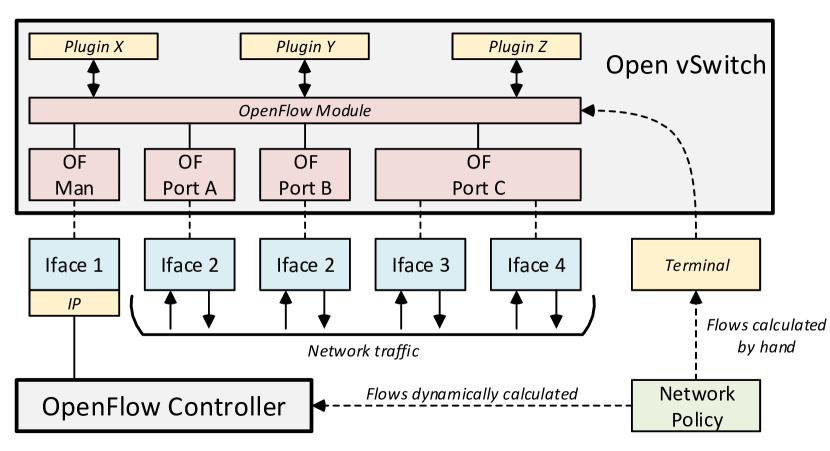
Although Open vSwitch (OVS) is not specifically designed to enable the SDN philosophy, it is widely used by researchers and organizations to test OpenFlow implementations and benefit from flexible SDN configurations. OVS can be configured to turn regular servers and computers with multiple physical network interfaces into a virtual OpenFlow switch, as shown in figure 5. Many Linux distributions, such as the Ubuntu OS, support OVS installation from their repositories.
Depending on the required configuration, OVS can be configured as a layer-2 switch (controlled by a local OVS-controller) or as a generic OpenFlow switch. Configuration of the OpenFlow module can be supplied by an external OpenFlow controller or Flow Rules are supplied manually via the command line interface. External plug-ins can also configure the OpenFlow module of OVS. An example of such a plug-in is the Quantum plug-in from OpenStack [17].
IV Graphical SDN Framework
To differentiate and compare the existing SDN solutions, we have developed a graphical SDN framework. Within the graphical framework multiple layers are defined, which indicate the hierarchy level of components within SDN networks (see figure 6).
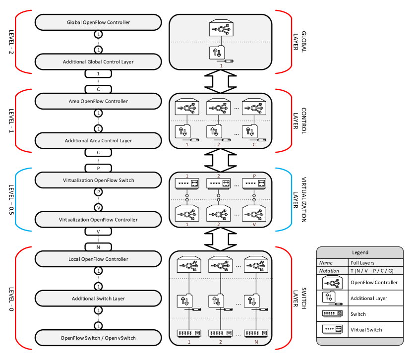
For our graphical framework we define that controllers perform the computations and tasks to control traffic and additional layers can be added for administrative and synchronizing purposes. In the following we explain the layers of figure 6.
-
•
Level-0 - Switch Layer - The lowest layer identified in the OpenFlow structure is the switch layer, with the main purpose to deliver data plane functionality. Data plane functions are performed at the Switch / Open vSwitch sublayer, where the two additional sub-layers, being the Additional Switch Layer and Local OpenFlow Controller, add additional functionality to perform minor control plane tasks;
-
•
Level-0.5 - Virtualization Layer - On top of the switch layer, the Virtualization Layer can be placed with the main function to divide and share the switch resources over multiple OpenFlow controllers. It enables multiple virtual network topologies on top of a single physical infrastructure. Resources of physical switches are virtualized by this layer and presented to the Control Layer as multiple virtual switches;
-
•
Level-1 - Control Layer - The functionality of the control layer is to perform the tasks of the SDN control plane in a defined area of the network topology for a number of switches. Decisions made at this layer influence only a part of the network and are locally optimal. In regular OpenFlow configurations, only a single Area OpenFlow Controller is present. Solutions have been proposed to enhance the control layer with additional area OpenFlow layers to extend functionality, such as synchronization of Flow Rules with other controllers;
-
•
Level-2 - Global Layer - The top layer has the functionality to control network topology at a global level, where forwarding and routing decisions influence the whole topology. A Global OpenFlow Controller can thus compute globally optimal routes through the network, as it controls all switches. The structure of the global layer is similar to the control layer.
To indicate the numerical relationship between the layers, the UML-standard, as used in object-oriented programming, is used as guidance in the framework in figure 6. The relationship states that the components (sub-layers) at each level share a one-to-one relationship () with each other. From the switch level a many-to-many or many-to-few relationship exists with the virtualization layer () or control layer (), when no virtualization is applied. In the case of virtualization, a many-to-few or many-to-many relation () indicates virtual switches are controlled by OpenFlow controllers. Within a domain, multiple area controllers can be controlled by a single centralized controller with the global view of the network. In case of an inter-domain network infrastructure, global layers can be interconnected.
| Symbol | Description | Relation |
|---|---|---|
| No. Switches | ||
| No. Virtual controllers | , | |
| No. Virtual switches | ||
| No. Area OpenFlow Controllers | ,, | |
| or | ||
| Global controller enabled | ||
| Layer enhanced for security | ||
| Layer enhanced for scalability | ||
| Layer enhanced for resiliency | ||
| Backup component available |
In order to differentiate multiple network topologies using the UML relationships, we use the following notation. For network topology the notation is given as , where the description of the used symbols is given in table II. The notation with the defined symbols of table II would not cover the entire framework, as additional sub-layers or applications are not indicated. Therefore an extra indicator is added to the OpenFlow notation, to indicate if an enhancement is added and for which enhancement area (security, scalability and/or resiliency) the enhancement is added. Beside additional components to the layers, it is possible from OpenFlow protocol version 1.2 to add redundant controllers to the control plane. Therefore the backup indicator is defined. When an enhancement overlaps multiple areas or when a component is applied redundantly, it is possible to combine indicators. The controller indicates a security enhanced controller that is redundantly applied.
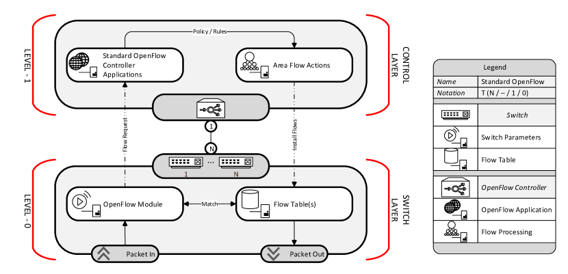
Before multiple OpenFlow enhancement proposals will be discussed, a reference OpenFlow network configuration is given in the figure 7. The reference configuration is indicated by , where the infrastructure is built up from switches controlled by general OpenFlow controllers.
The flow of actions in figure 7 is as follows. Network traffic, in the form of data packets, arrives at the switch data plane, where the packet headers are matched to a set of flow rules stored in the flow tables. When no match is found, the OpenFlow module of the switch will initiate a flow request to the assigned controller. The controller will process the event and install the needed flow rules into the switches at the designated route through the network, based on the policy and rules defined in the forwarding and routing applications of the controller.
V Scalability in SDN
By introducing a centralized authority to control the network traffic over a large network, the growth of network traffic may not scale with the performance of the controller [4]. Multiple proposals have been introduced [18, 19, 20, 21, 22] to create a distributed centralized authority, to solve the concerns on scalability and performance. In this section, these proposals will be discussed and projected onto our developed graphical framework.
V-A HyperFlow
The proposed solution by Tootoonchian et al. [19] to solve the scalability problem in SDN and OpenFlow networks is to deploy multiple OpenFlow controllers in the network infrastructure and implement a distributed event-based control plane, resulting in a structure. The improvement in scalability and performance is found in the placement of multiple controllers close to the switches, reducing flow setup times, while each controller is provided with the global view of the network. Another advantage of this approach is the resiliency against network partitioning (disconnected network) in case of network failures, as the views of the connected switches and controllers are synchronized.
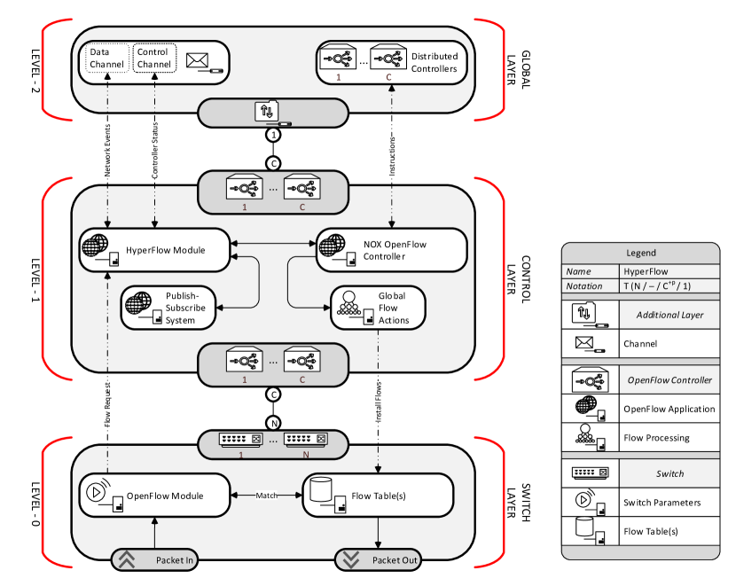
HyperFlow, see figure 8, is built up from three layers, where no virtualization is applied. The architecture at the switch level (data plane) and the OpenFlow specification are unmodified, which makes the HyperFlow concept applicable to current SDN-capable networks. At the control layer the HyperFlow application is connected to a standard NOX controller. To enable communication with the global layer, a publish-subscribe system is placed at the additional control layer to locally store the network status and view. The HyperFlow distributed global layer consists of three parts: the data channel, control channel and the distribution of functionality among the controllers. On the data channel, network events are distributed by the HyperFlow application. These events are stored in the publish-subscribe system, which synchronizes the global view of the controllers, but can operate independently in case of partitioning. The control channel is used for monitoring the status of the controllers. The distribution of functionality among the controllers is realized as follows. Each controller has a global view of the network and its status, it has capabilities to install flows into all switches. All required flows for a particular data stream are published to all distributed controllers to synchronize network state. The HyperFlow application on the controllers filter the requested flows for the switches assigned to it and will install the flows accordingly.
In [19] no extensive measurements are performed on different network topologies and traffic loads, thus no conclusion can be drawn from the HyperFlow approach to improve scalability in real-life SDN networks. Besides that, there are some limitations in the HyperFlow design. The first limitation was found by the authors themselves in the performance of the publish-subscribe system (WheelFS). All network events, flow installs and status information need to be synchronized between the multiple controllers, which requires a fast distributed storage system. In HyperFlow the performance of the publish-subscribe system was limited to approximately events per second. This does not indicate that the controllers are limited in processing, but the global view of the network controllers may not quickly converge. A second limitation is the lack of a management application in the global layer. In [19] no distinction is made between the functionality of the switches and controllers. This assumes that a global policy for Flow Rule installations must be configured in all assigned controllers. The last limitation is found in the performance of HyperFlow, where network traffic may be dropped when the offered load exceeds a controller’s capacity. Although the load on controllers can be reduced by assigning less switches to a controller, a single switch processing many flows may still overload its controller. We think a solution where Flow Requests can be forwarded to neighbor controllers for processing or smart applications at the switch layer to off-load controllers could be another solution.
V-B ONIX
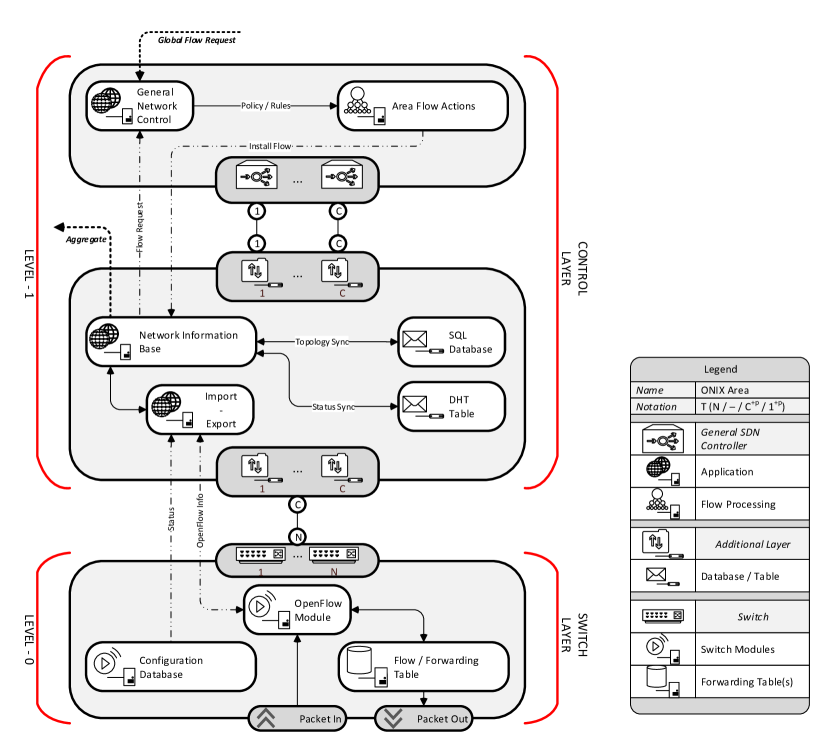
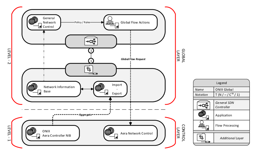
ONIX [21] is not built on-top of an OpenFlow controller, but can be classified as a “General SDN Controller.” The approach the developers took to abstract the network view and overcome scalability problems, was to add an additional distributed control platform. By adding an additional platform, the management and network control functions from the control plane are separated from each other. The management functions, used for link status and topology monitoring, are performed by the ONIX control platform and reduce the workload for a general flow controller. To partition the workload at the control platform, multiple ONIX instances can be installed to manage a subset of switches in the network infrastructure. The available information is synchronized between the ONIX instances, forming a distributed layer as seen with HyperFlow in section V-A, but now at the controller layer. A network controller assigned to a part of the network, can subtract information from the distributed layer to calculate area flows. In order to calculate global flows, ONIX has the capability to aggregate information from multiple area platforms to a global distributed platform. The aggregation of information and the calculation of global optimal forwarding rules is similar to the routing of internet traffic over multiple autonomous systems (ASes) [23], where the route between ASes is globally determined, but the optimal route inside the autonomous system is calculated locally. With this general introduction, we can conclude that ONIX can be classified as a SDN topology111In this overview the network scope is limited to a single domain, but the capabilities of ONIX can reach beyond that scope as it is designed for large-scale production networks.. With the use of figure 9 more insight is given in the design and functioning of ONIX at area level, while figure 10 shows how global flows are calculated using the distributed control platform.
At switch layer no modifications are required for ONIX and two channels connect to the switch with the Import-Export module at the distributed platform. The ONIX platform is an application that runs on dedicated servers and requires no specific hardware to function. According to the load and traffic intensity, multiple switches are assigned to an ONIX instance. Multiple ONIX instances combined form the distributed control platform. The first channel connects the configuration database and is used for managing and accessing general switch configuration and status information. To manage the forwarding, flow tables and switch port status, the second channel is connected to the OpenFlow module of the switch. The information and configuration status collected by the import-export module represent the network state of the connected switches and is stored in the Network Information Base (NIB) as a network graph. The NIB uses two data stores, being a SQL-database for slow changing topology information and a Dynamic Hash Table (DHT-table) for rapid and frequent status changes (such as link utilization and round trip times). The application of two data stores overcomes the performance issues faced by HyperFlow. From the NIB, a general flow controller or control logic can receive flow requests, switch status and network topology and compute paths. In comparison to the reference OpenFlow controller (figure 6), the ONIX platform has the availability of switch and link status information. Computation of paths is thus not limited by the information provided by the OpenFlow protocol. The last step in the flow setup process is to install the computed flows in the switch forwarding table via the ONIX distributed platform.
In [21] evaluation results are shown of measurements on the ONIX distributed layer to determine the performance of a single ONIX instance, multiple instances, replication times between the data stores and recovery times on switch failures. Unfortunately no information is present of the used control logic and the performance gain in comparison with regular OpenFlow controllers. The advantage of the ONIX distributed control platform is the partitioning of the workload over multiple instances. So, if an ONIX instance is limiting traffic throughput (dropping flow requests) due to high workload, assigned switches can be reassigned to other ONIX instances.
V-C DevoFlow
The approach of DevoFlow [18] is guided by two observations. First, the amount of traffic between the data and control planes needs to be reduced, because the current hardware OpenFlow switches are not optimized for inter-plane communication. Second, the high number of flow requests must be limited, because the processing power of a single OpenFlow controller may not scale with network traffic. To limit the traffic and flow requests to the control plane, traffic may be categorized into micro and elephant flows. In DevoFlow micro flows will be processed at the switch layer, without the need of the control layer. The DevoFlow philosophy is that only heavy traffic users, elephant flows, need flow management. By limiting the management to elephant flows, only one controller is needed in the network topology, shifting the routing complexity to the switch layer. With this information we classified the DevoFlow solution as a SDN topology.
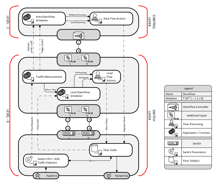
In figure 11, the DevoFlow solution is drawn as an additional layer on top of the physical switch to simplify the representation, but the actual implementation is performed at the soft- and firmware of the switch. This indicates that modifications to the standard switch are required. To ease integration of DevoFlow with other SDN concepts, no modifications are made to the OpenFlow protocol and controller. The destination of arriving packets is compared to flow rules installed in the switch table. When no match is found, a flow request must be initiated by the “Traffic Measurement” module in the switch. The traffic measurement module monitors the packets in the data flows and computes statistics. At the start of a flow each flow is marked as a micro flow and an existing flow rule from the forwarding table is cloned and modified by the “Local Flow Scheduler.” The modification to the flow rules allows multipath routing and re-routing. In case that multiple paths between the switch and destination exist, the local flow scheduler can select one of the possible ports and the micro-flow rule for that port is cloned. Re-routing is applied when one of the available switch ports is down and traffic needs alternative paths through the network.
To detect and route elephant flows through the network, the area scheduler can use four different schemes:
-
•
Wild-card routing - The switch pushes the available traffic statistics to the controller with a specified time interval. The scheduler pro-actively calculates unique spanning trees for all destinations in the network topology using the least-congested route and install the trees as flows in the switch flow tables. So for each destination in the network a flow is present in the switches and no flow requests are needed from the switch to the OpenFlow controller;
-
•
Pull-based statistics - The scheduler regularly pulls the traffic statistics from the switch and determines if elephant flows are present in the current data flows. Once an elephant flow is detected, the scheduler determines the least-congested path for this flow and installs the required flow rules at the switches;
-
•
Sampled statistics - This method is very similar to the pull-based scheme, but instead of pulling traffic statistics every time period, the switch samples traffic statistics into a bundle and pushes the bundle to the scheduler. At the scheduler, it is again determined if any elephant flows are present and on positive identification flows are installed, as described in the pull-based scheme;
-
•
Threshold - For each flow at the switch, the amount of transferred data is monitored. Once a flow exceeds a specified threshold, a trigger is sent to the scheduler and the least-congested path is installed into the switches.
All schemes are based on traffic statistics, where flows are only installed if identified as elephant flows in a reactive manner. In [18] multiple simulations have been performed on a large data network simulator to capture the behavior of flows through the network and measure data throughput, control traffic and the size of flow tables in the switches. The results show that the pull-based scheme with a short update interval maximizes the data throughput in the network. This performance comes at a price, as much traffic is initialized between the switch and controller and the size of the flow table is significantly large in comparison with the other schemes. The threshold scheme is identified as most optimal, as the data throughput is high, less traffic is required between the switch and the controller and the size of the flow table is minimal. Another advantage is the required workload on the scheduler in the controller, as no traffic statistics have to be monitored and processed.
V-D Kandoo
In [20] Kandoo is presented with similar goals and philosophy as DevoFlow, namely to limit the overhead of events between the data and control planes, but solves the problem by applying more controllers in a network topology. Kandoo differentiates two layers of controllers, namely local controllers, which are located close to the switches for local event processing, and a root controller for network-wide routing solutions. In practice this means that local controllers will process the micro flows and a trigger from the local controller must inform the root controller about the presence of an elephant flow. The number of local controllers depends on the amount of traffic (local events) and the workload on the controller, which is somewhat similar to the approach of ONIX and its distributed control platform. In an extreme case, every switch is assigned to one local controller. Translating Kandoo to the graphical framework, the root controller is located at the global layer and the local controllers can be found on the area or switch layer. If the extreme case is valid, the local controller can be seen as an extension of the switch layer and the topology can be classified as . In a regular architecture, where more than one switch is assigned to a local controller, a SDN topology is found. Figure 12 projects the regular case of Kandoo.
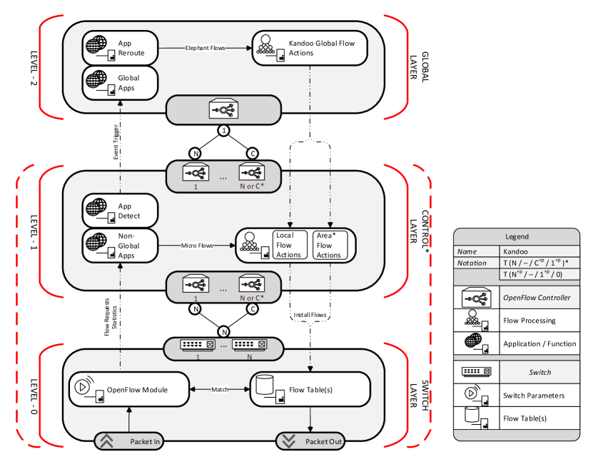
Kandoo leaves the software in the switch unmodified and shifts the processing of events to local controllers. The local controllers are standard OpenFlow controllers extended with a Kandoo module. This approach keeps the communication between the switch and controller standardized and gives the possibility to utilize standard OpenFlow applications. The Kandoo module intercepts the OpenFlow traffic and monitors it for elephant flows using the “App Detect” application. As long as no elephant flow is detected, the local controller processes the flow requests as micro flows. Elephant flows are detected using the threshold scheme from DevoFlow, which relays an event to the Kandoo module of the root controller in case of positive detection.
To propagate events from the local controllers to the root controller, a messaging channel is used. The root controller must subscribe to this channel in order to receive events. After receiving an elephant flow detection trigger, the “App Re-Route” determines an optimal route and requests the local controllers to install this route. The developers of [20] have not given any information on how the re-routing process is executed and which routing schemes are used.
Some measurements have been performed on a (small) tree topology with the Kandoo framework installed. Results show comparisons between the topology in a standard OpenFlow and Kandoo configuration. As expected, less events are processed by the root controller, but no information is given about the workload and performance of the local controllers. Overall we can state that the simulations and measurements are too limited to give a good indication of the performance enhancement provided by Kandoo. The limiting factor in the Kandoo configuration is the interface between the switch and the local controller, as in DevoFlow is shown that this interface is the limiting factor in current SDN network implementations. If the limit on this interface is not reached, the layered controller solution is an interesting concept which can also be useful to tackle security and resiliency problems.
V-E FlowVisor
Virtualization is a widely applied technique allowing multiple instances on the same hardware resources. Hardware resources are abstracted by an abstraction layer and presented to a virtualization layer. On top of the virtualization layer, instances are presented with virtualized hardware resources that one can control as if without virtualization. This approach is roughly similar to the SDN philosophy, but in FlowVisor by Sherwood et al. [22] the virtualization approach is reapplied, where OpenFlow-compliant switches are offered to the FlowVisor abstraction layer. FlowVisor offers slices of the network topology to multiple OpenFlow guest controllers, where the slices are presented as virtual OpenFlow switches. The guest controllers control the slices, where FlowVisor translates the configurations and network policies from each slice to Flow Rules on the physical OpenFlow switches. If this approach is applied to large networks, scalability problems can be resolved as control of the OpenFlow switches is divided over multiple controllers. To distinguish network slices, four dimensions are defined in FlowVisor:
-
•
Slice - Set of Flow Rules on a selection of switches of the network topology to route traffic;
-
•
Separation - FlowVisor must ensure that guest controllers only can control and observe the assigned part of the topology;
-
•
Sharing - Bandwidth available on the topology must be shared over the slices, where minimum data rates can be assigned for each slice;
-
•
Partitioning - FlowVisor must partition the Flow Tables from the hardware OpenFlow switches and keep track of the flows of each guest controller.
With these four dimensions and definitions, OpenFlow resources can be virtualized and shared over multiple instances. This means that a single hardware OpenFlow switch can be controlled by multiple guest controllers. To provide more details on the functioning of network virtualization in OpenFlow, FlowVisor is represented in figure 13.
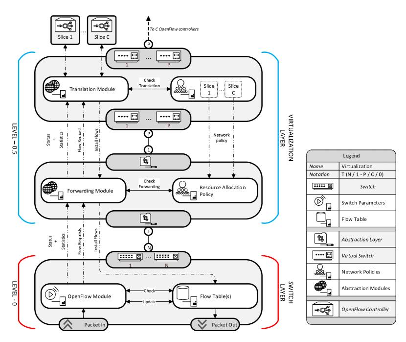
As illustrated in figure 13, FlowVisor acts like a transparent layer between hardware switches and the controllers. Hardware OpenFlow switches are assigned to the virtualization layer, where FlowVisor advertises itself as a controller. OpenFlow traffic is transmitted to FlowVisor at the virtualization layer, where the network capacity is sliced and divided over multiple users. The FlowVisor Forwarding Module checks on policy violations, before traffic is sent to the Translation module at the virtual OpenFlow switch. At the translation module, the traffic is translated and sent to the guest controllers, assigned to the corresponding slices. Flows coming from the guest controllers are checked on interference with the slice policy and translated to flows for the hardware switches. Via the forwarding module the guest flows are installed at the switches. The projection shows a straight forward example of a configuration, where one FlowVisor instance performs all virtualization tasks, but more complex configurations are possible.
Adding an additional layer between the switch and control layer creates unwanted overhead. Experiments show that response times for the processing of Flow Requests increased from ms to ms. This means that FlowVisor accounts for an additional delay of ms, in comparison to non-virtualized OpenFlow topologies [22]. Besides the delay measurements, experiments were performed to test bandwidth sharing between slices and CPU utilization on the hardware OpenFlow switches. Network policies must include minimal bandwidth guarantees (QoS parameters) for each user, to prevent unfair use of the network.
An aspect not covered in FlowVisor is security. Additional mechanisms for classification of traffic and checking of Flow Rules may be required to ensure full separation and isolation between network traffic on the slices.
V-F Conclusion on scalability
Five different concepts on scalability have been reviewed. All solutions propose to divide workload over multiple instances. However, it remains difficult to come with an optimal scalability solution for SDN networks. As can be seen from table III, trade-offs have to be made by network designers and managers. Table III gives an overview of the proposed frameworks and their components. Besides observations from the review, also a column is defined for standardization. This indicates availability of used components in the framework. Unfortunately, only FlowVisor is available as open-source software, but on conceptual level standardized components can be used to reproduce the other proposed frameworks. A high standardization in the table indicates that the solution is built up from standard available OpenFlow components. A part of the table is dedicated to data storage solutions used in ONIX and HyperFlow and is useful for future distributed layer developments and comparisons.
| Solution | Standarized | Complexity | Decision | Classification |
|---|---|---|---|---|
| HyperFlow | Global | X | ||
| ONIX | Global | X | ||
| DevoFlow | Semi-Global | V | ||
| Kandoo | Semi-Global | V | ||
| FlowVisor | Semi-Global | X | ||
| Solution | Availability | Performance | Reliability | |
| WheelFS | ||||
| DHT | ||||
| SQL |
VI Resiliency in SDN
In regular networks, when the control logic of a switch fails, only network traffic over that particular switch is affected. When failover paths are preprogrammed into neighboring switches, backup paths are available and on failure detection, backup paths can be activated. If the control logic in an SDN enabled network fails, the forwarding and routing capabilities of the network are down, resulting in drop of Flow Requests, undelivered data packets and an unreliable network. In an early stage of the development of the OpenFlow protocol, this problem was identified and from protocol version , a master-slave configuration at the control layer can be applied to increase the network resiliency to failing OpenFlow controllers.
We define robustness of a topology as the measure of connectivity in a network after removing links and switches. Its resiliency indicates its ability to re-allocate redundant paths within a specified time window. On the controller side, the robustness of a single or group of OpenFlow controller(s) is defined as the resistance of controller(s) before entering failure states. The resilience is defined as the ability to recover control logic after a failure. As described, the definitions for robustness and resiliency can have different meanings, depending on the viewpoint of the designer. In this overview, examples and proposals of both viewpoints are discussed.
Before proposed solutions on resiliency and robustness will be reviewed, a small retrospect to section V is made, as all those solutions house the ability to increase the robustness of an SDN network. By partitioning the workload of a single controller over multiple instances, the robustness of the network is increased. Failure of a single controller will only result in an uncontrollable part of the network. To recover from a failure and increase the resiliency, additional logic is required. For both viewpoints, timely detection of a failure and a fast failover process are basic requirements. To create a robust and resilient network, the network topology must include redundant paths [24]. For a resilient control layer, the network state must be synchronized and identical between master and slave controllers. Additional modules and synchronization schemes must meet these requirements without compromising the performance and adding unwanted latency.
This section will review resiliency of 3 different aspects important to the network: (1) Section VI-A focuses on the resiliency at the control layer; (2) Sections VI-B to VI-E give more insight in topology failure recovery and protection schemes, while section VI-F discusses the more special case of in-band networks where the control and forwarding plane share the same transport layer; (3) Finally, section VI-G SDN network security.
VI-A Replication component for controller resiliency
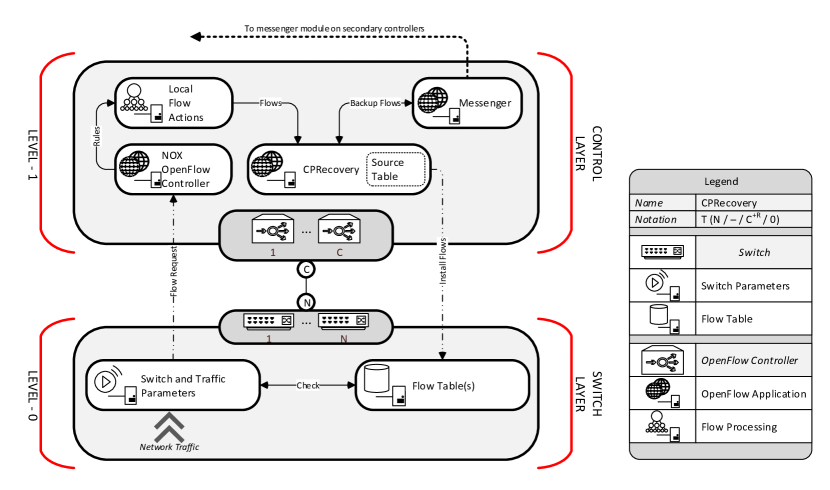
In [25] the master-slave capabilities of the OpenFlow protocol are utilized to deliver controller robustness. This indicates that a primary controller (master) has control over all switches and on the master failure, a backup controller (slave) can take over control of assigned switches. Fonseca et al. [25] introduce a solution, indicated in this review as CPR, which integrates a replication component into a standard OpenFlow controller. As replication component the “Primary-Backup” protocol is applied, to offer resilience against failures and a consistent view of the latest failure-free state of the network. The primary-backup protocol synchronizes the state of the primary controller with the backup controllers. In CPR two phases are distinguished, namely the replication and recovery phases. During the replication phase, calculated flows by the primary controller are synchronized over the backup controllers. After failure detection of the primary controller, the recovery process is initiated to reallocate a primary controller and restore flow calculations. With the replication component integrated in an OpenFlow controller, the solution can be classified as a topology. Hereby we denote that always one primary controller is present, with remaining backup controllers. The current implementation of the OpenFlow protocol allows a total of controllers. In figure 14 the synchronization process of CPR is shown.
The CPR solution connects to standard OpenFlow-compliant switches and is built upon the NOX OpenFlow controller. Additional components, to enable replication, are integrated into the NOX controller as modules. The switches are configured in the master-slave setting, allowing multiple controllers in a predefined listing. During the replication phase, flow requests are sent from the switch to the primary controller. At the controller, the ordinary processes are executed for routing and forwarding. After the flow is calculated in the area flow scheduler, it is intercepted by the “CPRecovery” module. This module determines whether the controller is assigned as primary and on positive identification the flow is added to the source table of the controller. Via the “Messenger” module, the source table of the backup controllers are synchronized using the primary-backup protocol. After all controllers are updated and synchronized, the flow is installed into the switches. This replication procedure enables a fully synchronized backup, before the flows are installed to the switches. So when the primary fails, the second assigned controller can seamlessly take over network control. A drawback of this replication scheme is the additional latency introduced to the complete flow install process.
All network switches can be configured to perform activity probing on the primary controller. If the primary controller fails to reply within a configurable time window (), the network switch starts the recovery phase and assigns the first backup controller from the list as primary controller. On the controller side, when a join request from the switches is received by a backup controller, this controller will set itself as primary controller and the replication phase is started. Update messages from the primary controller are also sent to the original primary controller and on its recovery it is assigned as one of the secondary controllers.
The replication and recovery processes seem to solve the resiliency problem with OpenFlow controllers, but the primary-backup protocol and the recovery phase may fail in case of a temporary network partitioning and geographically separated controllers. To explain the potential flaw, the example topology of figure 15 is used.
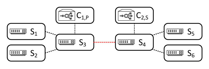
On normal operation, controller is assigned as primary and controller as secondary (backup) controller. At time the link becomes unavailable and the network is partitioned into two components by the following reasoning. Switches to are under control of the original primary controller, where the remaining switches ( to ) will select the secondary controller as new controller, as the time window on activity probing expires on . We question the behavior of the replication and recovery phase of the replication component (and the primary-backup protocol) in case link becomes operational. Switches to will not re-assign to the original primary controller, so the network topology remains partitioned until failure of controller . In [25] and other performed research no specific measurements are performed on the influence of geographical positioning of OpenFlow controllers and their secondary problems, like flow synchronizing and primary controller selection. To solve this problem, a more advanced synchronization scheme is required, with primary controller propagation and election schemes.
To test the functionality and the performance of the replication component, Fonseca et al. [25] performed two simulations. In the first simulation the packet delay between two hosts in a tree topology with the primary and backup controllers connected to the top switch are measured. At specific times the primary controller is forced into a failure state. Where the average packet delay is ms, the delay rises to approximately ms during the recovery phase. After the rise, the packet delay normalizes to average and the network functions normally. Although the replication phase is successful, the delay during the recovery phase is unacceptable for carrier-grade data networks providing voice services, which require end-to-end delays not to exceed ms.
The second simulation measured the response time of a flow install. Therefore multiple measurements have been performed using the number of secondary controllers as variable. As described earlier, the CPRecovery module first synchronizes the secondary controllers, before installing a computed Flow Rule into the switch Flow Table. The measurements show that the response time increases linearly with the number of secondary controllers, with a minimum response time of ms when no backup controller is configured and a maximum of ms with 3 secondary controllers to synchronize. The linear expansion of the response times is unacceptable for data networks. We propose to increase the performance of the CPRecovery module and lower the response times by performing the install of the Flow Rule and the synchronization to the secondary controllers in parallel or first installing the Flow Rule and perform synchronization afterwards.
VI-B Reactive link failure recovery
| Name | Update forwarding table | Recovery scheme | Recovery Time |
|---|---|---|---|
| L2-Learning | Traffic / ARP | - / ARP | Seconds - Minute |
| L2-Learning PySwitch | Traffic / ARP | Aging timers / ARP | Seconds - Minute |
| Routing | LLDP | Aging timers / LLDP | Seconds - Minute |
| Pre-determined | Manually | Configured | MilliSeconds |
In [26] three existing switching and routing modules (L2-Learning, PySwitch, Routing) from the NOX-controller are compared as recovery mechanisms. Additionally, a predetermined recovery mechanism is added. In the following the modules are discussed shortly on their ability to recover links.
-
•
L2-learning - The standard switching module of the NOX controller functions similarly to a common layer-2 switch. However, the applied NOX-controller lacks the Spanning Tree Protocol (STP);
-
•
L2-learning PySwitch - The functioning of this module is very similar to the standard L2-learning module. It is extended with two mechanisms to improve its performance. The first implemented extension adds aging timers to the installed Flow Rules, so that the switch can remove and update its Flow Table. Every time a switch processes a packet, the time-stamp of the flow rule is updated. To protect the Flow Table, the hard-time must be larger than the idle-time. The second mechanism applied is the application of STP [27], to remove possible networking loops in the topology;
-
•
Routing - The routing module uses three mechanisms to compute Flow Rules. To enable routing, the control must maintain the network topology for path computations. To detect connected switches and link failures, on a regular basis the switch sends Link Layer Discovery Protocol (LLDP) packets, containing information about the switch MAC-address, port number and VLAN indicator. A receiving OpenFlow switch replies with an LLDP-packet containing its own parameters. When the reply packet is received by the corresponding switch, the assigned controller is informed about the detected link and the network topology is updated. The recovery capabilities of the routing module depend on the discovery mechanism and the configured timeout interval. If an LLDP-packet is not received within the configured interval, the switch declares the link lost and informs the controller of the status change;
-
•
Pre-determined - The pre-determined module does not rely on learning and discovery mechanisms, but it implements path protection at the control layer. In the controller multiple static paths are provided by the network manager. Based on priority and available paths, the controller chooses a path and installs it on the switches accordingly. On a network failure the controller can choose a redundant path from the provided paths, reducing the need for link discovery mechanisms and path calculations. As the network manager provides the paths, no spanning tree protocol is needed (assuming that the paths are loop-free).
The first three mechanisms work dynamically and provide path restoration, whereas the fourth mechanism is especially designed for path protection. This module applied to the topology leads to the classification , because additional logic is added to the controller to improve its performance on link resiliency. Figure 16 projects the four recovery mechanisms onto the graphical framework.
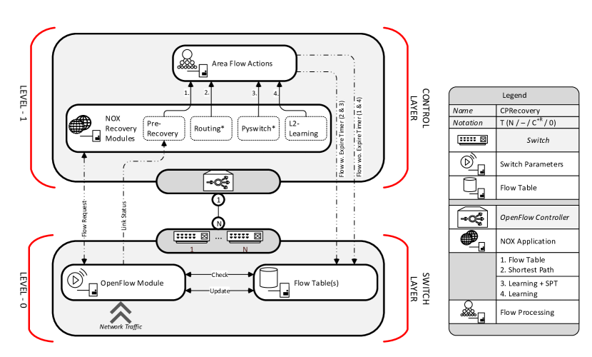
From the OpenFlow module at the switch, Flow Requests and link status information are exchanged with the controller. In figure 16 the four recovery modules are drawn, but only one module at a time is active. Furthermore, the routing and PySwitch modules are marked, to indicate the availability of the spanning tree protocol. Each of the modules can determine Flow Rules, based on the available information. The L2-learning and pre-determined modules install Flows without aging timers, while the routing and PySwitch modules set times to protect flow tables at the switch. In [26] simulations have been performed on a topology to show the behavior of the different modules and measurements have been taken to see if the link-recovery requirements are achievable. The topology contained multiple cycle and Sharma et al. [26] showed that much traffic is traversing between the OpenFlow switches and the controller, to maintain link-status information. Only the pre-determined module consumed less traffic, which is expected from its static and fixed design. To simulate network traffic, ping packets were sent with an interval of ms between two end-hosts. On a specified time, a link failure was initiated and the recovery time and number of dropped packets measured. Measurements show that it takes ms for a link failure detection to be indicated on the controller. This value is already above the required ms, so any recovery mechanism discussed in this research will fail. The pre-determined module acts immediately on a link failure, which results in recovery times of approximately ms, resulting in a total delay of ms. Results for the routing and PySwitch modules show that the recovery depends on the idle and hard times set in the aging timer. The L2-Learning mechanism fails recovery of a path without the application of the Address Recovery Protocol (ARP) [28]. Table IV summarizes the properties and results of the four recovery mechanisms, where a distinction is made on how topology (link) information is maintained, how the mechanism recovers from link failures and on what time scale paths are recovered.
Unfortunately, no experiments have been performed on varying the idle and hard times of the routing and PySwitch modules. Reducing these times, we believe, can have much influence on the recovery process of links. Also changing the default timeout timers of ARP and LLDP can improve the performance. The current implementation of the pre-determined module can act fast on a link failure, but lacks the ability of constructing paths on demand by using dynamically received topology information.
VI-C Path-based protection
As shown in the previous section, the reactive and pre-determined recovery schemes implemented at the control layer do not meet the ms recovery time requirement for carrier-grade networks. Sharma et al. [29] came with a similar proposal, but now applied on the switch layer. This reduces the recovery time, as no communication with the control layer is required. Multiple schemes can be applied to recover paths in case of link failures, where a distinction can be made between protection and restoration schemes [24]. Protection schemes do not need communication with the controller to restore paths, as actions are pre-configured at the switch layer. Restoration schemes require communication between the switch and controller and recovery paths are dynamically allocated.
In [29] the protection scheme is implemented as a protection mechanism at the switch layer, where refers to activating a backup path after failure of the primary path. To enable this mechanism, the Group Table concept of the OpenFlow protocol is utilized. In normal operation, the destination address from a packet is matched in the Flow Table and the packet will be forwarded to the correct port or dropped. By applying Group Tables, a flow rule can also contain a link to a unique group. In the Group Table, one or more Action Buckets define actions based on status parameters. On change of these parameters, the action bucket executes a predefined action. In case of the protection scheme, when a failure is detected in the path, the backup path is enabled for the flow. For path failure detection the Bidirectional Forwarding Detection (BFD) [30] protocol is implemented. To monitor the complete path between multiple OpenFlow switches, a BFD session is configured between the entry and exit switches. If the periodical messaging over the session fails, BFD assumes the path lost, updates the action bucket in the OpenFlow switches and the protected path is installed. The protection scheme implemented on a topology leads to a system.
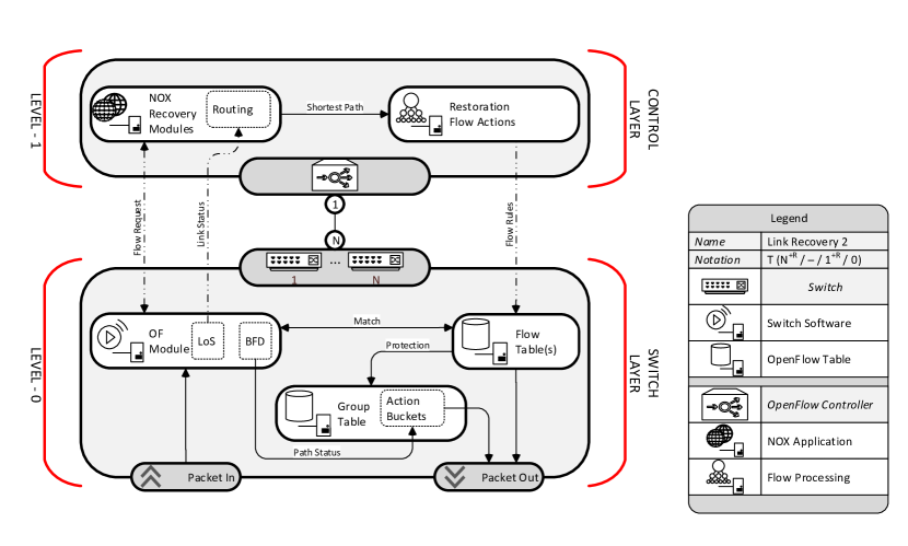
The second implementation in [29] is the restoration scheme at the switch layer. An extension to the standard routing module of the NOX controller is made to increase the resiliency. The failure detection capabilities of the routing module depend on the OpenFlow aging timers and the implementation of a topology module incorporating LLDP packets. The extended routing module uses the “Loss of Signal” (LoS) failure detection mechanism available in the OpenFlow protocol. LoS detects port changes in the switch from “Up” to “Down” and reports these to the controller. Other than BFD, LoS does not monitor complete paths, but only local links at the switch. On link failure detection, a notification is sent to the routing module and a new path is constructed, without incorporating the failed link. The new path with its corresponding flow rules are installed in the switches, after which the path is recovered. The proposed solution for path restoration is classified as .
The protection scheme most likely restores paths faster, as no communication is required with the controller and backup paths are preconfigured. The restoration scheme is more adaptive and is more flexible, as paths are calculated with status parameters of the current topology. In a large network, both schemes can be applied, depending on the network services provided. A combined scheme can be classified as a topology, as shown in figure 17.
In normal operation, the process of packet forwarding is similar to the standard OpenFlow operation. On protected paths, the BFD protocol monitors the status and on failure the action buckets in the Group Table are updated. Actions defined in the Action Buckets, enable the protected path. In case of restoration, the OpenFlow module monitors a link failure, after which the routing module in the controller constructs and installs a new path. An important aspect of the recovery process is the latency between time of link failure and the recovery of all affected flows. In [29] an analytical model is given for the restoration process. It gives a good indication where the latency is introduced in the recovery process. We have extended the model with the protection scheme, to indicate the differences between both recovery schemes.
| (1) |
The total restoration time () is determined by the loss-of-signal failure detection time (), the total time spent at the controller to look up the failed link (), the path calculation time (), the flow install / modification time () and the number of flows () to restore. In here the propagation delay, which is assumed to be small (ms), is integrated with the failure detection and flow installation time. The protection model depends on the BFD failure detection time (), the time to process the action bucket () and the number of flows affected by the link failure (). Because a broken flow is only restored after the processing of the “slowest” of switches in the path, the max operator is applied.
To give an indication of the latency differences, multiple simulations and measurements have been performed on different topologies in [29]. Results are show in table V. Delay times to process the action buckets are unknown and likely not more than several milliseconds.
| Time | Symbol | Delay (ms) | Relation | Comment |
|---|---|---|---|---|
| Failure detection time () | 40 - 44 | Fixed | ||
| Failure detection time () | 100 - 200 | Fixed | ||
| Controller look-up time () | 1 - 10 | Linear | Delay with 250 - 3000 flows | |
| Path calculation time () | 10 - 200 | Linear | Delay with 25 - 300 paths | |
| Flow installation time () | 1 - 5 | Linear | Delay with 1000 - 10000 flows |
Both recovery schemes were able to recover paths on link failure. The main difference in performance is found in the failure detection mechanism. Where BFD only needs ms to detect a path failure, the LoS mechanism takes more than 100 ms to report a broken link. A main disadvantage of the application of BFD in the protection scheme is the introduced overhead for monitoring all paths. Furthermore, the fixed pre-planned configuration is inflexible and the experiments were performed in such a way that link failures did not influence the protected paths. Restoration is more flexible by allocating restoration paths dynamically with up-to-date network topology information. Recovery times for both schemes mainly depend on the number of flows to recover in the network. Restoration times can exceed ms, if a large number of flows need recovering.
VI-D Link-based protection
In addition to the path-based discovery discussed in the previous section, Van Adrichem et al. [31] propose to deploy link-based monitoring and protection to overcome topology failure. Their contribution in minimizing recovery time is twofold:
-
1.
They minimize failure detection time. By using link-based, instead of path-based, BFD monitoring sessions, the per-session RTT and thus BFD interval window is minimized compared to per-path sessions. Experiments show that configurations with a BFD interval window of ms are feasible.
-
2.
They adapt the Group Table implementation of the OpenFlow capable software switch Open vSwitch to consider BFD status real-time, hence eliminating the administrative processes of bringing an interface’ status down.
Herewith, they enable a controller to employ protection by configuring per-switch backup paths using BFD aware Group Table rules. Where path-based failure monitoring has a complexity of sessions, link-based failure monitoring decreases to a complexity of , where and respectively represent the number of nodes and links in a network. Hence, the number of BFD sessions traversing each link is limited to exactly .
The experiments of [31] show a recovery time as low as ms independent of network size. Instead, due to the software nature of Open vSwitch - the solution scales to the degree of each node, emphasizing the need for hardware implementations of BFD and packet forwarding.
Since the proposed solution deploys per-switch backup paths, in exceptional cases crankback routing may need to be applied. Where a fast failure recovery is still guaranteed, the solution is suboptimal. However, in time the network controller will be notified of the change in topology and can reconfigure the network to an optimal state without service interruption.
VI-E Segment-based protection
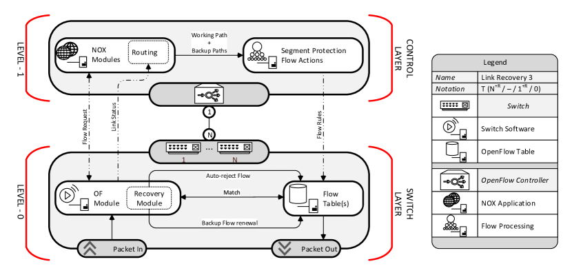
Where the previous two sections discuss path- and link-based protection against network failure, the research in [32] proposes a hybrid approach, where individual segments of a path are protected. The main idea is to provide a working path, as well as a backup path for each switch invoked in the working path. Both paths are installed in the Flow Tables with different priorities and after failure detection, the flows for the working path are removed from the table by additional mechanisms in OpenFlow, after which the backup flow becomes the working path. In figure 18 the projection to the graphical framework is given (note the overlap with figure 17).
The failure detection mechanism in [32] is unknown and to trigger the backup paths, two additional modules are added to the OpenFlow protocol version 1.0. For removing the flows for the working path from the Flow Table, an “auto-reject” mechanism is developed. This mechanism deletes entries when the port status from the OpenFlow switches changes. The second developed mechanism “flow renewal” is used to update flow entries for the backup paths. Backup paths are installed using idle timers and while the working path is active, update messages are transmitted over the backup paths to update the idle timers, preventing automatic flow removal by OpenFlow.
Multiple experiments have been performed with the adapted version of OpenFlow, utilizing segment protection with the “auto-reject” and “flow renewal” mechanisms. Results show average recovery times with a variable number of flow entries per switch around ms, with a maximum of ms. The fact that modifications and extensions must be made to the OpenFlow protocol, leading to a non-standard implementation, makes that we do not recommend the solution in [32] for large SDN implementations.
VI-F In-band OpenFlow networks
In sections (VI-B) to (VI-E), the controller was connected in an “out-of-band” configuration, which indicates that separate connections from the switch to the controller are available. Only control traffic traverses over these connections, ensuring no delays or traffic congestion between controller and switches. In an “in-band” configuration, control traffic traverses the same connections as data traffic. No additional network interfaces are needed. With the application of an in-band configuration to a network, Sharma et al. [33] discovered a problem. When a link failure occurs and the communication between a switch and controller is lost, the basic operations for a switch are to restore the connection by requesting a new connection after waiting for an echo request timeout. The minimum value for the timeout is limited to second, which is a magnitude of too long for proper path recovery in carrier-grade networks. Therefore in [33] the restoration and protection schemes from [29] are reused to solve the problem.
As seen before, data traffic paths can be restored or protected from a link failure. In case of restoration, the failed data traffic paths cannot be restored without communication channels between the switches and the controller. Therefore, first the control path must be restored after which the data paths can be reinstalled on the switches by the controller. In order to implement this priority of processing the link failure, the “Barrier Request and Reply Messages” concept from the OpenFlow protocol is utilized. In “normal” operation, OpenFlow messages can be reordered by the switches for performance gains. To stop reordering, Barrier Messages are sent by the controller and the switches must, upon receiving a Barrier Request, process all preceding instructions before processing the following request. After processing of the Barrier Request, a reply is sent to the controller. To clarify the restoration process in an in-band configuration, an example topology with process description is given in figure 19.
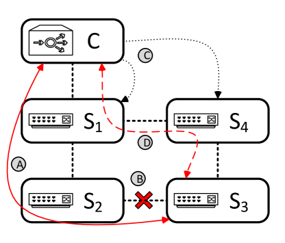
In figure 19, in total four phases are distinguished from normal operation to link failure and restoration of the control channel for switch :
-
•
Phase A - Initial phase where the control traffic for switch is routed over switch and to the controller. In a normal “out-of-band” configuration, would have a separate network connection with the controller;
-
•
Phase B - The link between switches and fails and the communication between and the controller stops. Switch monitors the link failure with the LoS mechanism and sends an error report to the controller via ;
-
•
Phase C - The controller calculates the new control path over and to with highest priority, whereafter the data traffic paths are recalculated. These paths cannot yet be installed into switch , as the broken path is still present in the flow table. Therefore the controller first updates and ;
-
•
Phase D - The flow modification messages are processed and the reply message is sent to the controller by and . After both barrier reply messages are received by the controller, the new control path to switch is configured at the intermediate switches. The connection to the controller is restored and the recalculated data paths can be installed in all switches.
As seen in the description of the phases, the use of barrier requests synchronizes the intermediate steps of restoration. Besides restoration, the control traffic path can also be recovered by a protection scheme. Protection of the control and data traffic paths is provided by BFD link failure detection and the Group Tables with Action Buckets. Main advantages of protection is that no communication is required and the switches can autonomously update their flow tables.
Using the restoration and protection schemes, a total of four recovery schemes are possible. As with the out-of-band configuration, analytical models can be used to predict the behavior during the recovery process. The restoration model for the control traffic path is a modification of the earlier restoration model. Equations (3) and (4) show the restoration times for an OpenFlow in-band configuration, where is the control traffic restoration time, is the additional time delay introduced by the Barrier Message reply mechanism and is the time to install and modify the flow tables of intermediate switches. The restoration time for data traffic paths () is a simplified form of equation (1), without the LoS failure detection delay as the controller already is informed about the network failure.
| (3) |
| (4) |
In table VI the four recovery schemes are given, together with the analytical delay models.
| Recovery Scheme (Control - Data) | Symbol | Analytical Relationship |
|---|---|---|
| Restoration - Restoration | ||
| Restoration - Protection | ||
| Protection - Protection | ||
| Protection - Restoration |
The analytical relationships in table VI assume that the recovery and protection processes do not influence each other at the switch. In [33] multiple measurements have been preformed on all four in-band recovery schemes. Results show that when restoration is applied to recover data paths, delays exceed the ms requirement. Only the full protection recovery scheme meets the requirements, but in practice this scheme will not be applied due to large flow tables and the large number of configurations which have to be made by the network manager at the switches.
Looking to the differences in the results between and , we can conclude that the performance difference is small222Results show a of approximately ms in comparison with ms measured in [29].. This is expected, as only a few control paths to the switches have to be recovered. With this conclusion, we can state that for recovery requirements there is no noticeable performance difference between in- and out-of-band configurations, when a full protection scheme is implemented. A comparison between restoration in both configurations is not possible due to the differentiation in delay in the measurements of [29] and [33]. We think it is possible to predict the behavior for both configurations with the derived analytical models, when reliable measurements for the defined parameters are present.
VI-G Security in SDN
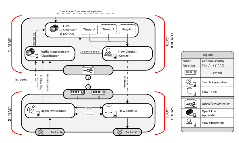
Network security is applied to control networks access, provide separation between users and protect the network against malicious and unwanted intruders. It remains a hot topic under SDN researchers, because a basic security level is expected from a new network technology, as well as the fact that network security applications can easily be applied to the network control logic. We define two levels of security. The first level invokes logical connections between end hosts inside the network. Protocols like Secure Socket Layer (SSL) or packet encrypting techniques must ensure connection security. Within SDN, this level of security plays an important role, as the control link between switches and the centralized controller must be ensured. In the OpenFlow protocol a mechanism to secure the connection is available, but not required. It is up to the controller to secure the connection with the switches and a number of controller implementations have not implemented link security mechanisms. When no link security is applied, a malicious node can impersonate the controller and take over control of the switches.
The second level of security is to protect switches, servers and end hosts in the network. Numerous examples are present to indicate the threats to the network as a whole. Malicious software can intrude the network, infect hosts and gather information, but also flooding attacks can disable network servers or overload OpenFlow switches and controllers. Security mechanisms must be implemented on the network to detect malicious traffic and take necessary actions to block and reroute this traffic. In current networking, network security is applied at higher networking layers. Routers and firewalls perform security tasks at layer 3, whereas end hosts and servers host security applications at layer 7. With SDN, there is a central authority that routes traffic through the network and enables the possibility to apply security policies to all layers in networking. Much research has been performed and the results of [34, 35, 36, 37] are used to determine security properties within SDN. Most researchers follow roughly the same procedure to apply security to the network. This procedure consists on three steps where a short description of the process is given, as well as a reference to the performed research.
-
•
Classification - Data flows through the network must be classified in order to determine malicious behavior and network attacks. Without classification it is impossible to protect the network and perform countermeasures. The main source for traffic classification is found in traffic statistics [35];
-
•
Action - Once a traffic flow is marked as malicious, the control layer must modify flow tables to protect the network and prevent propagation of the malicious traffic through the network. For each threat, different actions are needed, so the control layer must be flexible for quick adoption of new protection schemes [34];
-
•
Check - The last security process is the checking of calculated flow rules with the applied security policy from the network manager. Flow rules may (unintentionally) disrupt the security policy and therefore an extra control process is needed. Preventing network security violations by checking flow rules before install on the switches, completes the overall security process [36, 37].
The three processes combined form the protection layer for the network and all can be implemented at the control layer, which results in a configuration. To give the most general view of this configuration, we assume no modifications to the switch layer. Figure 20 gives the general OpenFlow security configuration.
As seen in figure 20, normal Flow Requests and traffic statistics enter the classification module in the OpenFlow controller. Traffic statistics can originate from the OpenFlow module at the switch and result from processed TCP and UDP traffic dumps. The classification module identifies malicious traffic flows and has two actions to perform. First, it must inform the Flow Scheduler with the presence of malicious flows in the network. Existing flows in the switch tables must be modified by the Flow Scheduler. Second, incoming Flow Requests must be marked, so that the flow scheduler can process the Flow Requests according to the security policy. At the scheduler, multiple security modules are present, to install and modify Flow Tables with rules based on the security policy for regular traffic and counter measures for the different threats to the network. So for each traffic flow there exists a unique set of rules, in order to protect the individual traffic flows within the network, as well as the network itself. The last step before Flow Rules can be installed or modified is confirming validity to the overall security policy of the network. A computed Flow Rule by a module in the Flow Scheduler can confirm the rule of that module, but may violate the security policies of other modules and the overall network security policy. After a Flow Rule is approved by such a flow policy checker, it can be installed into the switch Flow Tables.
In theory, the classification process looks easy to execute, but [35] and [34] have proven otherwise. In [35] an effective solution is found to identify abnormal traffic and flooding attacks. The most obvious mechanism to classify traffic flows are continuous TCP and UDP traffic dumps. With these dumps, all information is present to identify malicious traffic, but it takes much computing resources to process all the dumps continuously. Therefore an intelligent mechanism is employed to map traffic flows based on traffic statistics. Using the maps, all flows are characterized and abnormal traffic flows can be identified and removed from the network. This method is only to detect flooding attacks, so to detect other threats, more classification mechanisms are needed. In [34] an application layer is presented to apply classification modules, as well as security modules, at the Flow Scheduler. A general application layer eases implementation of modules for newly identified threats. Multiple examples in [34] show that with the application of classification and security modules, counter measures for network threats can be implemented into an OpenFlow environment.
VI-H Conclusion on resiliency
Where [25] focuses on the resiliency of the control plane and developed a mechanism to utilize the master-slave concept for OpenFlow controllers, [26, 29, 31, 32, 33] research the ability to recover failed links. On the controller side we can state that a single controller is insufficient in terms of robustness by a lack of redundancy. With the failure of a controller the OpenFlow switches will lose the control layer functionality, resulting in an uncontrolled network topology. If the ms recovery requirement from carrier-grade networks is applied, the replication scheme used to improve robustness will not suffice. Hence, the replication component needs modifications to lower the repair latency.
On link recovery, five papers are discussed. Although most recovery concepts start with “traditional” failure recovery based on Loss-of-Signal to detect failure, these methods have proven to have a large latency. Instead, actively probing failure detection mechanisms can detect failures more quickly. Group Tables with pre-programmed failover logic and fast restoration of flows by the controller are two proven techniques which have shown to recover paths within sub ms time. Hence, recovery from topology failure appears sufficiently covered.
However, an integral solution, where also OpenFlow controllers are redundantly applied, with the ability to recover network control in millisecond order, needs further research. Techniques used in the scalability research field can be joined with the OpenFlow protocol to apply master-slave configurations. Combined with proposed path recovery schemes a higher level of resilience can be reached in both the control and forwarding plane.
VII Conclusion
In this overview, we have discussed the basic principles of SDN, where the control layer is decoupled from the data plane and merged into a centralized control logic. The centralized logic, itself controlled by software, has a global view of the network and has the capabilities to dynamically control hardware devices for optimal traffic flows through the network. For communication between the data plane and the control logic, the OpenFlow protocol is commonly utilized. Two main problem areas are identified from the reviewed research, being limited scalability and decreased resiliency due to the centralized nature of SDN.
To gain detailed insight on performed research in SDN and OpenFlow networks, we have developed a general framework and notation in which we classify scientific work related to scalability and resiliency in SDN. We have made a separation in proposed solutions based on scalability and resiliency issues. Due to the centralization of the control logic, scalability issues exist on the number of hardware devices to control by a single control logic or the number of Flow Requests processed by the logic. Solutions can be found in increasing performance of the central logic, reducing the number of tasks to perform by the central control logic or dividing hardware resources with either virtualization or introducing multiple coexisting controllers.
On resiliency three problem areas have been distinguished, being the resistance of both the controller and the network topology against failures, as well as the network resilience against malicious attacks (security). Resiliency of SDN networks can be increased with the application of redundant network controllers and replication of internal network state, while recovery schemes can protect against network topology failures.
However, as each implementation seems to make trade-offs, possible solutions are still suboptimal by nature. The topics of scalability and topology failure may be sufficiently solved by combining the decrease of control overhead, distributing multiple controllers among a network, and deploying discussed failure protection mechanisms. The topic of recovery from controller failure, however, seems underrepresented and needs to be researched more thoroughly.
References
- [1] B. A. A. Nunes, M. Mendonca, X.-N. Nguyen, K. Obraczka, and T. Turletti, “A survey of software-defined networking: Past, present, and future of programmable networks,” Communications Surveys Tutorials, IEEE, vol. 16, no. 3, pp. 1617–1634, Third 2014.
- [2] N. Feamster, J. Rexford, and E. Zegura, “The road to sdn,” Queue, vol. 11, no. 12, p. 20, 2013.
- [3] S. Scott-Hayward, G. O’Callaghan, and S. Sezer, “Sdn security: A survey,” in Future Networks and Services (SDN4FNS), 2013 IEEE SDN for. IEEE, 2013, pp. 1–7.
- [4] S. H. Yeganeh, A. Tootoonchian, and Y. Ganjali, “On scalability of software-defined networking,” Communications Magazine, IEEE, vol. 51, no. 2, pp. 136–141, 2013.
- [5] S. Sezer, S. Scott-Hayward, P. K. Chouhan, B. Fraser, D. Lake, J. Finnegan, N. Viljoen, M. Miller, and N. Rao, “Are we ready for sdn? implementation challenges for software-defined networks,” Communications Magazine, IEEE, vol. 51, no. 7, 2013.
- [6] K. Suzuki, K. Sonoda, N. Tomizawa, Y. Yakuwa, T. Uchida, Y. Higuchi, T. Tonouchi, and H. Shimonishi, “A survey on openflow technologies,” IEICE Transactions on Communications, vol. 97, no. 2, pp. 375–386, 2014.
- [7] A. Lara, A. Kolasani, and B. Ramamurthy, “Network innovation using openflow: A survey,” Communications Surveys Tutorials, IEEE, vol. 16, no. 1, pp. 493–512, First 2014.
- [8] Open-Network-Foundation. (2013, apr) Openflow switch specification openflow version 1.3.2 (wire protocol 0x04).
- [9] A. Doria, J. H. Salim, R. Haas, H. Khosravi, W. Wang, L. Dong, R. Gopal, and J. Halpern, “Forwarding and Control Element Separation (ForCES) Protocol Specification,” RFC 5810 (Proposed Standard), Internet Engineering Task Force, Mar. 2010. [Online]. Available: http://www.ietf.org/rfc/rfc5810.txt
- [10] N. L. M. van Adrichem, C. Doerr, and F. A. Kuipers, “Opennetmon: Network monitoring in openflow software-defined networks,” in Network Operations and Management Symposium (NOMS), 2014 IEEE, May 2014.
- [11] N. Gude, T. Koponen, J. Pettit, B. Pfaff, M. Casado, N. McKeown, and S. Shenker, “Nox: towards an operating system for networks,” ACM SIGCOMM Computer Communication Review, vol. 38, no. 3, pp. 105–110, 2008.
- [12] Open-Network-Foundation. (2013) Open vswitch manual - ovs-vswitchdb.conf.db(5) 2.0.90. [Online]. Available: http://openvswitch.org/ovs-vswitchd.conf.db.5.pdf
- [13] Stanford University. (2014) Pox openflow controller wiki. [Online]. Available: https://openflow.stanford.edu/display/ONL/POX+Wiki
- [14] Nippon Telegraph and Telephone Corporation. (2014, jan) Ryu sdn controller. [Online]. Available: http://osrg.github.io/ryu/
- [15] Project-FloodLight. (2014, jan) Floodlight open sdn controller. [Online]. Available: http://www.projectfloodlight.org/floodlight/
- [16] Linux-Foundation. (2014, jan) Opendaylight project. [Online]. Available: http://www.opendaylight.org/
- [17] NEC-Corporation. (2014) Quantum plug-in for openstack cloud computing software. [Online]. Available: https://wiki.openstack.org/wiki/Neutron/NEC_OpenFlow_Plugin
- [18] A. R. Curtis, J. C. Mogul, J. Tourrilhes, P. Yalagandula, P. Sharma, and S. Banerjee, “Devoflow: Scaling flow management for high-performance networks,” in ACM SIGCOMM Computer Communication Review, vol. 41, no. 4. ACM, 2011, pp. 254–265.
- [19] A. Tootoonchian and Y. Ganjali, “Hyperflow: A distributed control plane for openflow,” in Proceedings of the 2010 internet network management conference on Research on enterprise networking. USENIX Association, 2010, pp. 3–3.
- [20] S. Hassas Yeganeh and Y. Ganjali, “Kandoo: a framework for efficient and scalable offloading of control applications,” in Proceedings of the first workshop on Hot topics in software defined networks. ACM, 2012, pp. 19–24.
- [21] T. Koponen, M. Casado, N. Gude, J. Stribling, L. Poutievski, M. Zhu, R. Ramanathan, Y. Iwata, H. Inoue, T. Hama et al., “Onix: A distributed control platform for large-scale production networks.” in OSDI, vol. 10, 2010, pp. 1–6.
- [22] R. Sherwood, G. Gibb, K.-K. Yap, G. Appenzeller, M. Casado, N. McKeown, and G. Parulkar, “Flowvisor: A network virtualization layer,” OpenFlow Switch Consortium, Tech. Rep, 2009.
- [23] J. Hawkinson and T. Bates, “Guidelines for creation, selection, and registration of an Autonomous System (AS),” RFC 1930 (Best Current Practice), Internet Engineering Task Force, Mar. 1996. [Online]. Available: http://www.ietf.org/rfc/rfc1930.txt
- [24] F. A. Kuipers, “An overview of algorithms for network survivability,” ISRN Communications and Networking, vol. 2012, p. 24, 2012.
- [25] P. Fonseca, R. Bennesby, E. Mota, and A. Passito, “A replication component for resilient openflow-based networking,” in Network Operations and Management Symposium (NOMS), 2012 IEEE. IEEE, 2012, pp. 933–939.
- [26] S. Sharma, D. Staessens, D. Colle, M. Pickavet, and P. Demeester, “Enabling fast failure recovery in openflow networks,” in Design of Reliable Communication Networks (DRCN), 2011 8th International Workshop on the. IEEE, 2011, pp. 164–171.
- [27] IEEE, “Ieee standard for local and metropolitan area networks: Media access control (mac) bridges,” Institute of Electrical and Electronics Engineers, WG802.1 Bridging and Management Working Group, Tech. Rep. 802.1D-2004, 2011.
- [28] D. Plummer, “Ethernet Address Resolution Protocol: Or Converting Network Protocol Addresses to 48.bit Ethernet Address for Transmission on Ethernet Hardware,” RFC 826 (INTERNET STANDARD), Internet Engineering Task Force, Nov. 1982, updated by RFCs 5227, 5494. [Online]. Available: http://www.ietf.org/rfc/rfc826.txt
- [29] S. Sharma, D. Staessens, D. Colle, M. Pickavet, and P. Demeester, “Openflow: meeting carrier-grade recovery requirements,” Computer Communications, 2012.
- [30] D. Katz and D. Ward, “Bidirectional Forwarding Detection (BFD),” RFC 5880 (Proposed Standard), Internet Engineering Task Force, Jun. 2010.
- [31] N. L. M. van Adrichem, B. J. van Asten, and F. A. Kuipers, “Fast recovery in software-defined networks,” in Software Defined Networks (EWSDN), 2014 Third European Workshop on. IEEE, 2014.
- [32] A. Sgambelluri, A. Giorgetti, F. Cugini, F. Paolucci, and P. Castoldi, “Openflow-based segment protection in ethernet networks,” Optical Communications and Networking, IEEE/OSA Journal of, vol. 5, no. 9, pp. 1066–1075, 2013.
- [33] S. Sharma, D. Staessens, D. Colle, M. Pickavet, and P. Demeester, “Fast failure recovery for in-band openflow networks,” in Design of Reliable Communication Networks (DRCN), 2013 9th International Conference on the. IEEE, 2013, pp. 52–59.
- [34] S. Shin, P. Porras, V. Yegneswaran, M. Fong, G. Gu, and M. Tyson, “Fresco: Modular composable security services for software-defined networks,” in Proceedings of Network and Distributed Security Symposium, 2013.
- [35] R. Braga, E. Mota, and A. Passito, “Lightweight ddos flooding attack detection using nox/openflow,” in Local Computer Networks (LCN), 2010 IEEE 35th Conference on. IEEE, 2010, pp. 408–415.
- [36] S. Son, S. Shin, V. Yegneswaran, P. Porras, and G. Gu, “Model checking invariant security properties in openflow,” in Communications (ICC), 2013 IEEE International Conference on, June 2013, pp. 1974–1979.
- [37] P. Porras, S. Shin, V. Yegneswaran, M. Fong, M. Tyson, and G. Gu, “A security enforcement kernel for openflow networks,” in Proceedings of the first workshop on Hot topics in software defined networks. ACM, 2012, pp. 121–126.