Solid state optical interconnect between distant superconducting quantum chips
Abstract
We propose a design for a quantum interface exploiting the electron spins in crystals to swap the quantum states between the optical and microwave. Using sideband driving of a superconducting flux qubit and a combined cavity/solid-state spin ensemble Raman transition, we demonstrate how a stimulated Raman adiabatic passage (STIRAP)-type operation can swap the quantum state between a superconducting flux qubit and an optical cavity mode with a fidelity higher than . We further consider two distant superconducting qubits with their respective interfaces joined by an optical fiber and show a quantum transfer fidelity exceeding between the two distant qubits.
pacs:
42.50.Ct, 85.25.Am, 03.67.Hk, 03.67.LxSuperconducting qubits (SQs) are one of the most promising technologies for delivering a quantum computer which will operate within a single superconducting chip Devoret and Schoelkopf (2013). Linking remotely distant superconducting chips via an optical data bus thus opens the door for a quantum internet J.Kimble (2008); Fröhlich et al. (2013); Zhang et al. (2013); Hammerer et al. (2010); Ritter et al. (2012). To permit the optical networking of superconducting quantum chips Devoret and Schoelkopf (2013), a coherent quantum interconnect between microwave and optical quantum information as a building block has been developed theoretically and experimentally Stannigel et al. (2010); Tian (2012); Wang and Clerk (2012); Barzanjeh et al. (2012); Xiang et al. (2013); Hafezi et al. (2012); Xia et al. (2014). One way to achieve this interlinking is to find a method to convert quantum information held within superconducting circuits into quantum information held in optical photons within one node (or interface), then transmit the photons over an optical fibre, and finally reconvert the photonic quantum information back into the target distant superconducting chip.
Researchers have recently focused much effort towards devising such a quantum interface, interconverting electromagnetic radiation at different frequencies using either optomechanical quantum systems Stannigel et al. (2010); Tian (2012); Wang and Clerk (2012); Barzanjeh et al. (2012); Xiang et al. (2013); Xia et al. (2014), or ensemble of ultracold atoms Hafezi et al. (2012). Although solid-state electronic ensembles have been experimentally demonstrated to be capable of coherent exchange with superconducting circuits Kubo et al. (2010); Schuster et al. (2010); Bushev et al. (2011); Zhu et al. (2012), only two proposals for a solid-state hybrid quantum interface have been proposed very recently Williamson et al. (2014); O’Brien et al. (2014), and one more abstract scheme for quantum state transfer between two remote NV centers Stannigel et al. (2010). Experimental progress in magneto-optic frequency conversion exploiting optomechanical resonators has been demonstrated for classical signals Bochmann et al. (2013); Andrews et al. (2014). We have recently described a design for a magneto-optomechanical quantum interface for and detailed how it can achieve high transfer fidelities between distant flux qubits Xia et al. (2014). All of the published proposals so far are technically challenging, using either optomechanical/magneto-optomechanical systems, or ensembles of trapped atoms in proximity to cryogenic superconducting circuits except O’Brien et al. (2014).
In this Letter we show how such an interconversion between microwave and optical quantum information and a quantum internet can be achieved through a solid-state electronic spin ensemble which catalyses the coupling between the flux qubit and photonic cavity mode.
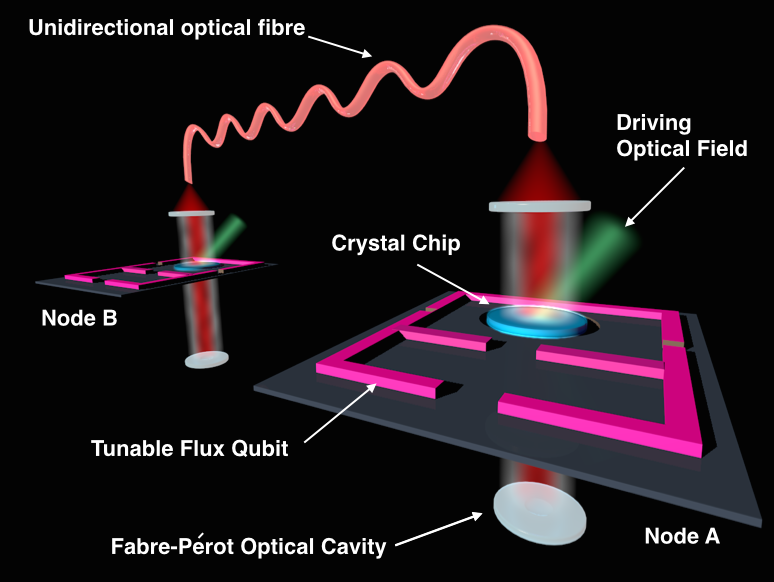
We begin by describing the schematic configuration for our quantum interface/node and later how to use two distant nodes to achieve quantum state transfer i.e. a quantum network (Fig. 1). Each node works as a quantum interface and composes of a Fabry-Pérot cavity, an ensemble of spins and a gap tunable four-Josephson-junction (4JJ) flux qubit. This 4JJ flux qubit is fabricated on top of a suitable substrate (dark plane) Fig. 1. In order to optically couple the ensemble of spins in a crystal chip, a round hole is cut in the main loop of the flux qubit such that the light in the Fabry-Pérot cavity can pass through it without significant absorption and scattering. The crystal chip covers the hole. The crystal chip is cut so that the [001] direction is along the axis, perpendicular to the plane of the flux qubit and parallel with the axis of the optical cavity. In this arrangement, the spin ensemble can effectively couple to both of the cavity mode and the magnetic field created by the flux qubit (see Supplementary Material for more details). We consider that an optical coherent control field irradiates the crystal chip at almost normal incidence to the chip. We first discuss the swapping of quantum information between the flux qubit and the optical cavity mode in a single node/interface but later will consider the quantum transfer between two nodes (the source), and (the target), which are optically connected via a unidirectional optical fiber. The latter only allows optical propagation along one direction, from node to node and can be realized using optical circulators Cirac et al. (1997).
We now describe the optical subsystem of each node and the unidirectional optical fibre couplings. We assume that the optical cavity mode in the node () has a resonance frequency and an intrinsic decay rate . It couples to an output optical fiber with a coupling rate and connects to the other node via this fiber. Thus the total decay rate becomes , and we assume with . represents the photon loss in the transfer. The denote the couplings into the waveguide connecting the two distant nodes. In this two node network, the Lindblad superoperator describing the one-way quantum connection breaking the time symmetry is given by , where () and () are the creation and annihilation operators of the cavity mode in node A (B).
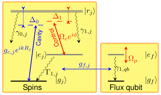
We next describe the crystal chip spin ensemble. We model the collection of electron spins as ensemble of three-level systems, as shown in Fig. 1(b). These could be either a collection of centers in diamond Acosta et al. (2013) or rare earth ion crystal such as ions in Baldit et al. (2010); Thomas Böttger and Cone (2006). Each spin system consists of three levels: the optical excited state , and two electronic ground states and . In the case of the we have , while for the system we have . The excited state decays to the state () with a rate (). Due to the coupling to the magnetic environment, the state also decays to with the rate and suffers pure dephasing of a rate . We can describe the ensemble of spins within each each node with the Hamiltonian () , where is the -component of the usual spin-1/2 Pauli operators for the th spin, is the zero-field splitting with G Hz [ G Hz ] for the [] centers, is the energy of the optical excited state . The second term in the above Hamiltonian describes the magnetic interaction with the spins with being the Landé factor of the spin. Note that the -factor of the electronic spin in can be up to Probst et al. (2013), which is much larger than in centers where and M Hz ⋅ m T -1 is the Bohr magneton. Here we neglect the terms related to the strain-induced splitting because they are very small and only shift the energy of state .
The 4JJ flux qubit can be modeled as a two-level system with the excite state and the ground state , and can be tuned by the flux biases and . The flux threading through the loop is used to tune the gap . We apply a time-dependent magnetic field to the loop and thus tune the gap of qubit. Thus the free Hamiltonian of the gap tunable flux qubit becomes , where with , ( is the external flux threading the qubit loop, the flux quantum and the persistent current), is the energy bias and is the tunnel splitting dependent on the bias , and . In the vicinity of we have . The flux qubit associated Pauli spin-half operators are defined as and . The decay and pure dephasing rates of the excited state of the flux qubit are denoted as and , respectively.
We now describe the tripartite interaction between the ensemble of spins, the cavity mode and the flux qubit within an individual node and which are graphically summarized in Fig 1(b). We consider an optical Raman transition between the two spin ground states and formed through a combination of the external driving classical optical field and the quantum optical cavity field. This optical driving of an individual spin at position together with the cavity mode drives the transition of with a rate and a phase , where the latter is dependent on the position and the wave vector of . The the coherent laser field , with the frequency and chirped phase , drives the transition of . The fluctuation in the coherent driving is taken into account by and . In the dispersive regime, these optical transitions form a Raman transition between the two ground states and , which is also arranged to dispersively couple to the flux qubit. Such optical type configuration has been demonstrated in both ensemble of centers Acosta et al. (2013), and host crystals Lauritzen et al. (2011); Bussieres et al. (2014); Baldit et al. (2010). The diamond crystal chip is synthesized with (001) surface orientation such that the magnetic field generated by the flux qubit has a component orthogonal to the principal () axes of the NV centers Zhu et al. (2012). The total Hamiltonian of the coupled system within one node is .
We consider the first-order sideband transition and adiabatically eliminate the optical excited state , then the Hamiltonian in the one-excitation space (OES) becomes (see supplementary information)
where is the chirp of the coherent driving. Here we define the detuning with , , and with , . means the statistical ensemble average. We have the identity . Under the two-photon resonance condition, , and we also have, , , , and we define the operators and , while is the Bessel function of the first kind. Here we assume that with , and set , and , with . Note that the detuning and the parameters are fixed once the setup is fabricated. A major advantage of our sideband transition configuration is that it allows one to modulate the coupling rate within the triparite configuration of flux-spin ensemble-optical mode. This flexibility will later permit us to use Stimulated Raman Adiabatic Passage (STIRAP) for quantum transfer and this has tremendous advantage as regards robustness to noise and parameter imprecision over fixed on-resonance coupling schemes for transfer Zhu et al. (2012); Saito et al. (2013).
We can now consider the swap of quantum information between the flux qubit and the optical cavity mode via the spin ensemble in one interface. We first determine a good model for the spin ensemble with inhomogeneous broadening in the transition frequencies and coupling rates. We divide the spins into groups and consider small inhomogeneities between the groups for the coupling rates , and transitions frequencies , and . This model reproduces quite precisely the Rabi oscillations observed in the experimental observation Zhu et al. (2012) (see Supplementary Material), and we use this model for our numerical investigations below. Correspondingly, the Jaynes Cummings coupling rates , and , are the cooperative coupling rates of the th group which is increased by a factor with respect to the single-spin coupling rate. Unlike the quantum memory by Zhu et al. Zhu et al. (2012), the strength of the overall magnetic coupling rate between the spin ensemble and the flux qubit is limited by the applicable thickness of the crystal chip hosting the spins. We will find that crystal chip must be quite thin to avoid degradation of the transfer fidelity due to phase mismatching and this reduced thickness restricts the degree of achievable magnetic coupling.
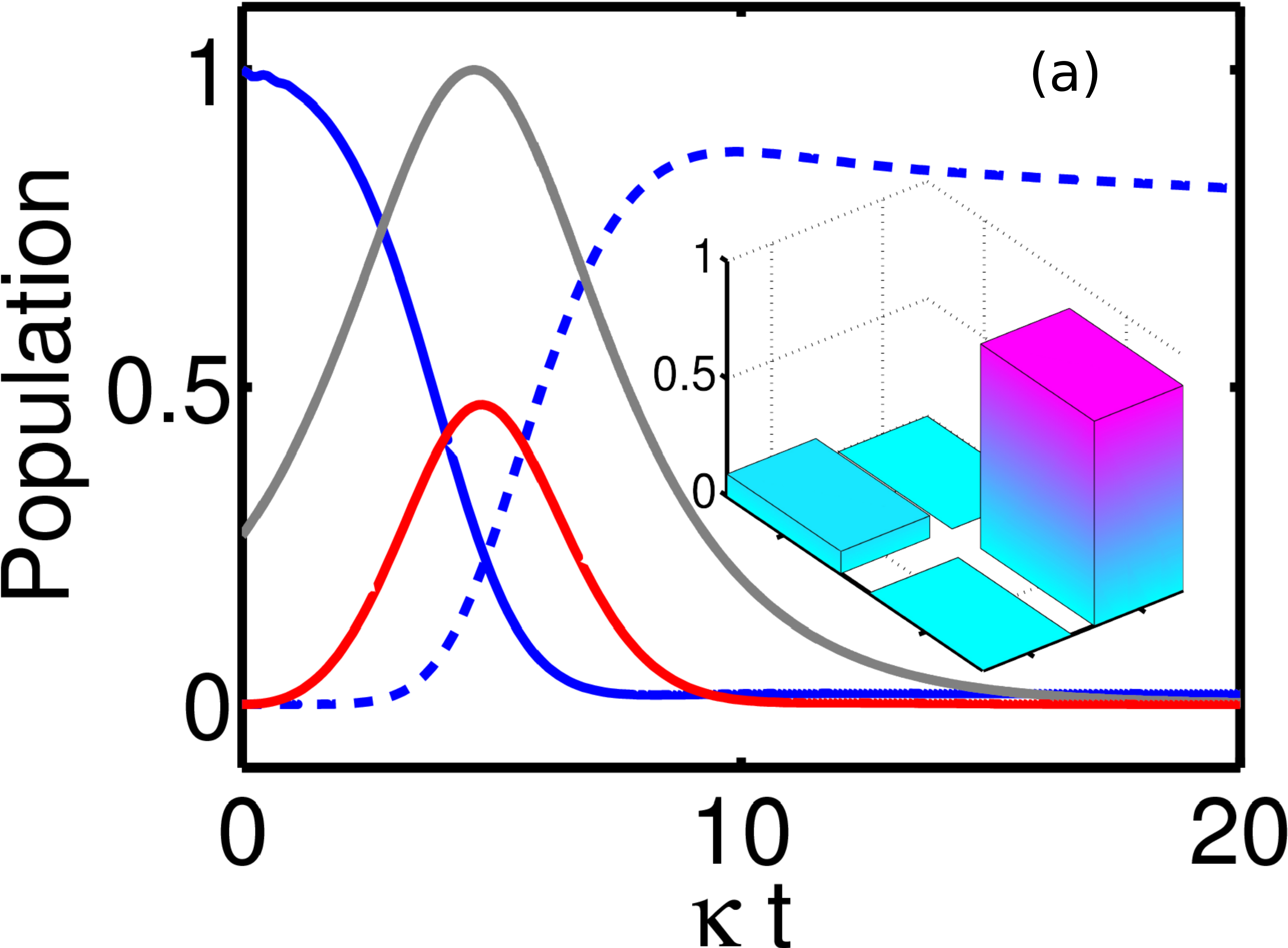
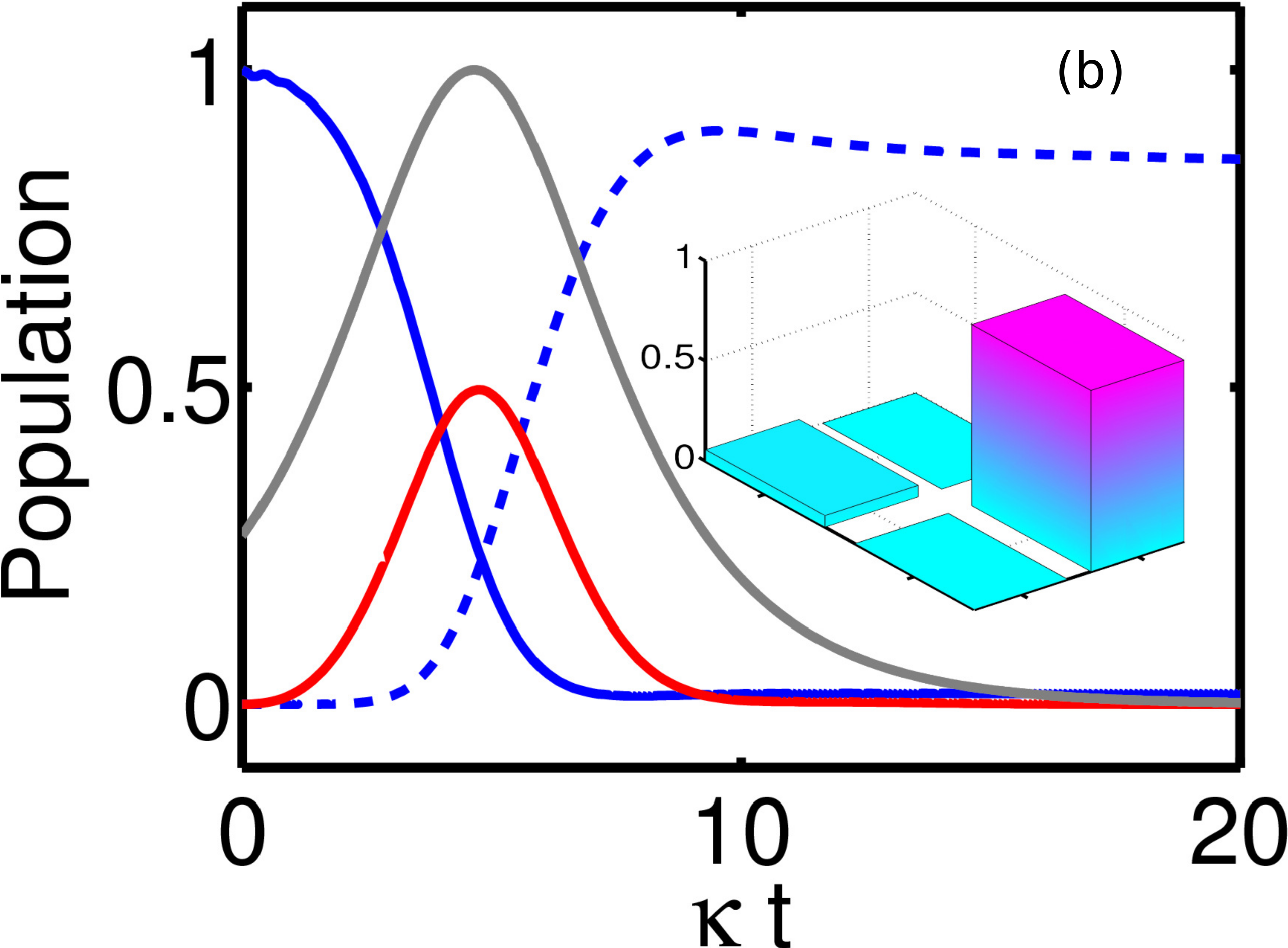
To swap quantum information from the flux qubit to the cavity mode we perform a two-photon resonant STIRAP transfer of the population from the flux qubit to the optical cavity, shown in Fig. 2. The system is initially populated in the excited state of the flux qubit, . We modulate the coherent optical driving and the flux bias such that two Rabi frequencies are Gaussian functions given by and with the amplitude , of the coherent classical optical control field. To minimize the operation time, the three subsystems interact on-resonance such that and yielding . For , we can finish the swap operation before the loss of the excitation due to any decay within the system. Here M Hz . An advantage of this STIRAP transfer is that the excitation of the spins is greatly suppressed. As a result, the detrimental effect of the inhomogeneous broadening of the spins is very small.
Figure 2 shows how well our STIRAP-based SWAP scheme works for M Hz , M Hz . Such high quality flux qubits Bylander et al. (2011); Fedorov et al. (2010) and Fabry-Pérot cavities Chen et al. (2013) are available using existing experimental technology. To perform the STIRAP control the pulse follows the pulse with a delay and n s (, see supplementary material). At , the fidelity of the photonic state reaches its maximum, corresponding to a population of . For M Hz , we can achieve a SWAP fidelity larger than if and M Hz . A simpler implementation of the STIRAP technology using a constant chip corresponding to the maximal ac Stark shift can still reaches at .
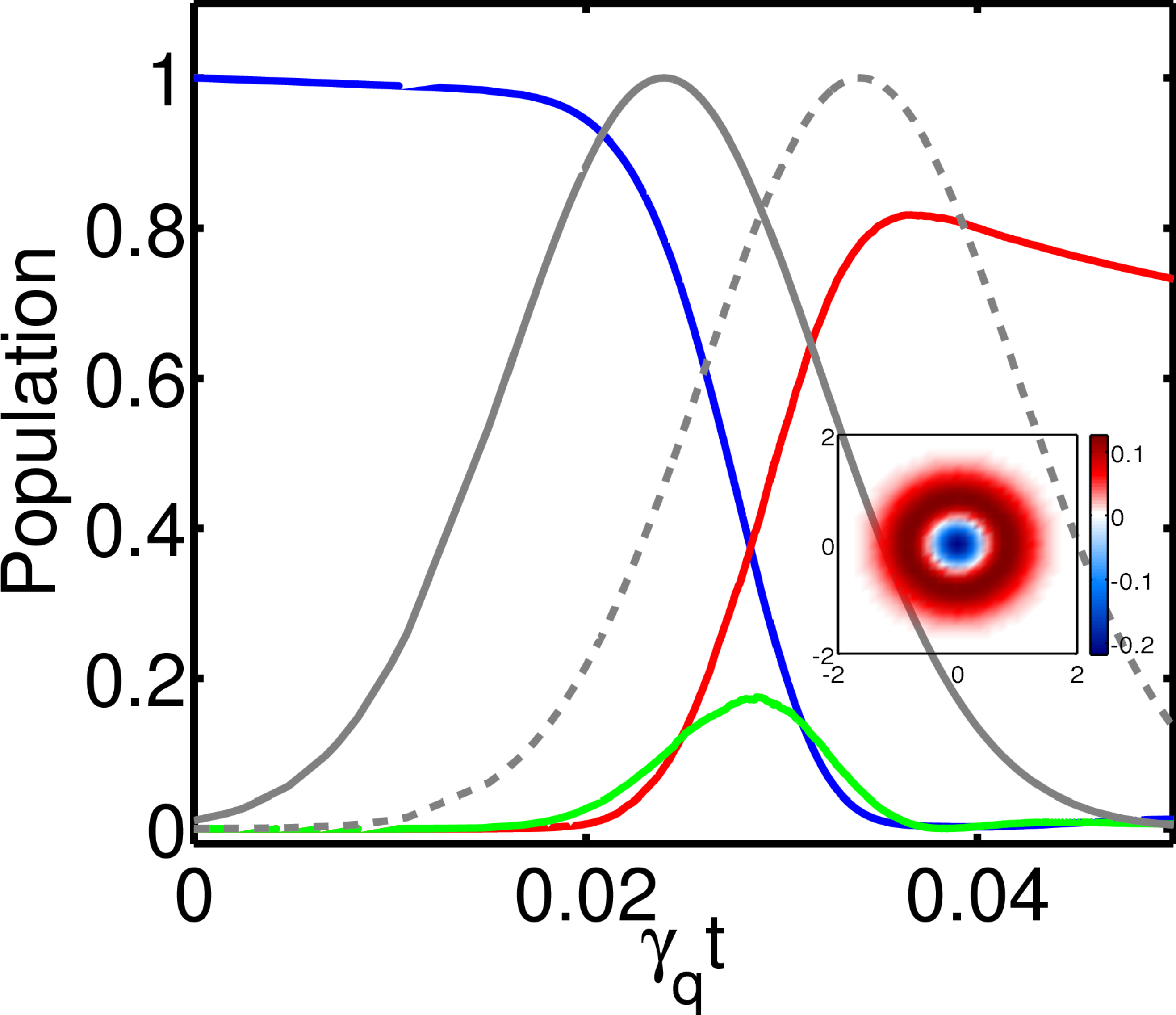
We can finally now seek to use our microwave-optical quantum interface to transfer quantum information between two remote superconducting qubits by exploiting the scheme proposed by Cirac et al. Cirac et al. (1997), to construct a quantum internet. To perform the quantum remote transfer we create a tripartite Raman transition where the spin ensemble dispersively couples to the flux qubits and the cavity modes with detuning . According to the CZKM scheme Cirac et al. (1997); Stace and Barnes (2002), we need only tune the coupling by modulating the control field and can set . In the simulation, we eliminate the small time delay in the control field of the node B related to the retardation in the propagation between two nodes Cirac et al. (1997). As an example, Fig. 3 shows the distant transfer of the quantum state from node A to node B. We assume that two nodes are identical. The flux qubit-spin ensemble coupling rates with M Hz is constant in time, while we modulate the optical Raman coupling via the classical laser driving field , with and . As a result, the excitation in the flux qubit in node A is transferred to the flux qubit in node B with a fidelity in excess of . For centers, we use the collective decay rate of the ensemble of spins M Hz for fitting the experimental data (see supplementary material). The quantum state of the flux qubit A can be transferred to qubit B with a fidelity of corresponding to a Node B population of at . While for the ensemble of , the spin magnetic excited state decay can be neglected as s Probst et al. (2013), and the inhomogeneous broadening is M Hz . This negligible decay increases the fidelity slightly to (Population of ).
Next we compare the available magnetic coupling rates in two implementations using centers or rare earth ions. A more detailed discussion can be found in section V of the supplementary material. Both the swapping and remote transfer of the quantum information require a strong coupling between the flux qubit and the spins. However the physical size of the spin ensemble is constrained by the area of the flux qubit and also the crystal chip must be quite thin to reduce the detrimental effects of optical phase mis-match on the transfer fidelity. Due to their large electron factors, rare earth ions like , can provide a coupling rate of about M Hz which is large enough for our task. However, the largest usable magnetic coupling strength between the flux qubit and the ensemble of centers is only about M Hz . This coupling rate is low to achieve a high fidelity swap of the flux qubit quantum state. To increase the coupling rate, we can focus the magnetic flux on the small diamond chip using superconducting flux focusing techniques. Flux focusing can greatly increase the magnetic field strength over the focusing region Lipworth et al. (2013); Wu et al. (2006); Matlashov et al. (1991), and utilising this our scheme can be usefully applied to an ensemble of centers to achieve good transfer fidelities.
In summary, we have proposed a theoretical scheme for an all-solid-state quantum interface between microwave and optical quantum information with sufficient tunability to permit local and long-distance high fidelity quantum transfer. We show that by coupling a superconducting circuit magnetically to an ensemble of three level color centers or rare-earth ions, where the latter also couples to an optical cavity mode, we are able to use the STIRAP technique to swap the quantum state between the superconducting qubit and the optical cavity. Using this quantum interface, we have demonstrated the proof-in-principle quantum network transferring the quantum information with a fidelity larger than between two remote superconducting qubits. This is an essential progress towards the realization of a quantum internet, in particular in the optical telecom C-band around µ m using the rare earth Er3+.
Acknowledgements
This work was partially funded by the Australian Research Council Centre of Excellence for Engineered Quantum Systems (EQuS), project number, CE110001013.
References
- Devoret and Schoelkopf (2013) M. H. Devoret and R. J. Schoelkopf, Science 339, 1169 (2013).
- J.Kimble (2008) H. J.Kimble, Nature 453, 1023 (2008).
- Fröhlich et al. (2013) B. Fröhlich, J. F. Dynes, M. Lucamarini, A. W. Sharpe, Z. Yuan, and A. J. Shields, Nature 501, 69 (2013).
- Zhang et al. (2013) J. Zhang, Y. Liu, Şahin Kaya Özdemir, R.-B. Wu, F. Gao, X.-B. Wang, L. Yang, and F. Nori, Scientific Rep. 3, 2211 (2013).
- Hammerer et al. (2010) K. Hammerer, A. S. Sørensen, and E. S. Polzik, Rev Mod Phys 82, 1041 (2010).
- Ritter et al. (2012) S. Ritter, C. Nölleke, C. Hahn, A. Reiserer, A. Neuzner, M. Uphoff, M. Mücke, E. Figueroa, J. Bochmann, and G. Rempe, Nature 484, 195 (2012).
- Stannigel et al. (2010) K. Stannigel, P. Rabl, A. S. Sorensen, P. Zoller, and M. D. Lukin, Phys Rev Lett 105, 220501 (2010).
- Tian (2012) L. Tian, Phys Rev Lett 108, 153604 (2012).
- Wang and Clerk (2012) Y.-D. Wang and A. A. Clerk, Phys Rev Lett 108, 153603 (2012).
- Barzanjeh et al. (2012) S. Barzanjeh, M. Abdi, G. J. Milburn, P. Tombesi, and D. Vitali, Phys Rev Lett 109, 130503 (2012).
- Xiang et al. (2013) Z.-L. Xiang, S. Ashhab, J. Q. You, and F. Nori, Rev Mod Phys 85, 623 (2013).
- Hafezi et al. (2012) M. Hafezi, Z. Kim, S. L. Rolston, L. A. Orozco, B. L. Lev, and J. M. Taylor, Phys Rev A 85, 020302 (2012).
- Xia et al. (2014) K. Xia, M. R. Vanner, and J. Twamley, Scientific Rep. 4, 5571 (2014).
- Kubo et al. (2010) Y. Kubo, F. R. Ong, P. Bertet, D. Vion, V. Jacques, D. Zheng, A. Dreau, J. F. Roch, A. Auffeves, F. Jelezko, et al., Phys Rev Lett 105, 140502 (2010).
- Schuster et al. (2010) D. I. Schuster, A. P. Sears, E. Ginossar, L. DiCarlo, L. Frunzio, J. J. L. Morton, H. Wu, G. A. D. Briggs, B. B. Buckley, D. D. Awschalom, et al., Phys Rev Lett 105, 140501 (2010).
- Bushev et al. (2011) P. Bushev, A. K. Feofanov, H. Rotzinger, I. Protopopov, J. H. Cole, C. M. Wilson, G. Fischer, A. Lukashenko, and A. V. Ustinov, Phys Rev B 84, 060501 (2011).
- Zhu et al. (2012) X. Zhu, S. Saito, A. Kemp, K. Kakuyanagi, S.-i. Karimoto, H. Nakano, W. J. Munro, Y. Tokura, M. S. Everitt, K. Nemoto, et al., Nature 478, 221 (2012).
- Williamson et al. (2014) L. A. Williamson, Y.-H. Chen, and J. J. Longdell (2014), URL arXiv:1403.1608v1.
- O’Brien et al. (2014) C. O’Brien, N. Lauk, S. Blum, G. Morigi, and M. Fleischhauer, Phys. Rev. Lett. 113, 063603 (2014).
- Bochmann et al. (2013) J. Bochmann, A. Vainsencher, D. D. Awschalom, and A. N. Cleland, Nat. Phys. 9, 712 (2013).
- Andrews et al. (2014) R. W. Andrews, R. W. Peterson, T. P. Purdy, K. Cicak, R. W. Simmonds, C. A. Rgal, and K. W. Lehnert, Nat. Phys. 10, 321 (2014).
- Cirac et al. (1997) J. I. Cirac, P. Zoller, H. J. Kimble, and H. Mabuchi, Phys Rev Lett 78, 3221 (1997).
- Acosta et al. (2013) V. M. Acosta, K. Jensen, C. Santori, D. Budker, and R. G. Beausoleil, Phys. Rev. Lett. 110, 213605 (2013).
- Baldit et al. (2010) E. Baldit, K. Bencheikh, P. Monnier, S. Briaudeau, J. A. Levenson, V. Crozatier, I. Lorgeré, F. Bretenaker, J. L. Le Gouët, O. Guillot-Noël, et al., Phys. Rev. B 81, 144303 (2010).
- Thomas Böttger and Cone (2006) C. W. T. Thomas Böttger, Y. Sun and R. L. Cone, Phys. Rev. B 74, 075107 (2006).
- Probst et al. (2013) S. Probst, H. Rotzinger, S. Wünsch, P. Jung, M. Jerger, M. Siegel, A. V. Ustinov, and P. A. Bushev, Phys. Rev. Lett. 110, 157001 (2013).
- Lauritzen et al. (2011) B. Lauritzen, J. c. v. Minář, H. de Riedmatten, M. Afzelius, and N. Gisin, Phys. Rev. A 83, 012318 (2011).
- Bussieres et al. (2014) F. Bussieres, C. Clausen, A. Tiranov, B. Korzh, V. B. Verma, S. W. Nam, F. Marsili, A. Ferrier, P. Goldner, H. Herrmann, et al., arxiv:1401.6958v1 (2014).
- Saito et al. (2013) S. Saito, X. Zhu, R. Amsüss, Y. Matsuzaki, K. Kakuyanagi, T. Shimo-Oka, N. Mizuochi, K. Nemoto, W. J. Munro, and K. Semba, Phys. Rev. Lett. 111, 107008 (2013).
- Bylander et al. (2011) J. Bylander, S. Gustavsson, F. Yan, F. Yoshihara, K. Harrabi, G. Fitch, D. G. Cory, Y. Nakamura, J.-S. Tsai, and W. D. Oliver, Nat Phys 7, 565 (2011).
- Fedorov et al. (2010) A. Fedorov, A. K. Feofanov, P. Macha, P. Forn-Díaz, C. J. P. M. Harmans, and J. E. Mooij, Phys Rev Lett 105, 060503 (2010).
- Chen et al. (2013) W. Chen, K. M. Beck, R. Bücker, M. Gullans, M. D. Lukin, H. Tanji-Suzuki, and V. Vuletić, Science 341, 768 (2013).
- Stace and Barnes (2002) T. M. Stace and C. H. W. Barnes, Phys. Rev. A 65, 062308 (2002).
- Lipworth et al. (2013) G. Lipworth, J. Ensworth, K. Seetharam, D. Huang, P. S. Jae Seung Lee, T. Nomura, M. S. Reynolds, D. R. Smith, and Y. Urzhumov, Scientific Rep. 4, 3642 (2013).
- Wu et al. (2006) C. H. Wu, M. H. Hsu, K. L. Chen, J. C. Chen, J. T. Jeng, T. S. Lai, H.-E. Horng, and H.-C. Yang, Supercond. Sci. Technol. 19, S246 (2006).
- Matlashov et al. (1991) A. N. Matlashov, V. P. Koshelets, P. V. Kalashnikov, Y. E. Zhuravlev, V. Y. Slobodchikov, S. A. Kovtonyuk, and L. V. Filippenko, IEEE Trans. Mag. 27, 2963 (1991).