Three-Dimensional Triplet Tracking for LHC and Future High Rate Experiments
Abstract
The hit combinatorial problem is a main challenge for track reconstruction and triggering at high rate experiments. At hadron colliders the dominant fraction of hits is due to low momentum tracks for which multiple scattering (MS) effects dominate the hit resolution. MS is also the dominating source for hit confusion and track uncertainties in low energy precision experiments. In all such environments, where MS dominates, track reconstruction and fitting can be largely simplified by using three-dimensional (3D) hit-triplets as provided by pixel detectors. This simplification is possible since track uncertainties are solely determined by MS if high precision spatial information is provided. Fitting of hit-triplets is especially simple for tracking detectors in solenoidal magnetic fields.
The over-constrained 3D-triplet method provides a complete set of track parameters and is robust against fake hit combinations. Full tracks can be reconstructed step-wise by connecting hit triplet combinations from different layers, thus heavily reducing the combinatorial problem and accelerating track linking.
The triplet method is ideally suited for pixel detectors where hits can be treated as 3D-space points. With the advent of relatively cheap and industrially available CMOS-sensors the construction of highly granular full scale pixel tracking detectors seems to be possible also for experiments at LHC or future high energy (hadron) colliders. In this paper tracking performance studies for full-scale pixel detectors, including their optimisation for 3D-triplet tracking, are presented. The results obtained for different types of tracker geometries and different reconstruction methods are compared. The potential of reducing the number of tracking layers and - along with that - the material budget using this new tracking concept is discussed. The possibility of using 3D-triplet tracking for triggering and fast online reconstruction is highlighted.
keywords:
LHC; Track Reconstruction; Track Trigger1 Introduction
Recent advances in semiconductor technology make it possible to produce pixel sensors at moderate costs. In particular Monolithic Active Pixel Sensors (MAPS) are very attractive as they allow to integrate the readout logic in the sensors itself, thus simplifying the detector fabrication (no bump bonding) and reducing material and power consumption. A particularly interesting variant are High-Voltage MAPS (HV-MAPS) [1, 2] as they collect the charge by drift and not by diffusion as standard MAPS sensors do. This feature allows to use CMOS sensors also in high rate experiments like LHC. Recent tests of HV-MAPS prototype sensors [3] show promising results and make people think about the idea to construct silicon-pixel only tracking detectors for future high rate and precision experiments. The dream to use an all-silicon pixel detector will soon come to reality in the Mu3e experiment [4, 5], which aims to search for the lepton flavor violating decays with a sensitivity of better than . The Mu3e experiment will mainly consist of a four-layer pixel detector with an active surface of about 1.5 m2 and almost 300 000 pixels. However scaling of such a big pixel detector to even larger sizes, for example LHC experiments, is not trivial at all. The main obstacles are the power dissipation of the active sensors and the small reticle sizes of the CMOS technology. On the other hand HV-MAPS have many advantages as they allow for a much simpler readout architecture (hit digitisation on sensor), reduced material budget (thinned sensors and no additional readout chips) and simplified detector design (no strip stereo layers, fewer layers, etc.).
A big advantage of pixel detectors is that only three sensor layers are needed to provide full tracking information. Because of the higher redundancy, the number of detector layers can be significantly reduced in a pixel-only design compared to a design based on silicon strips. Thus, the pixel related increase of the power consumption is expected to be fully compensated by reducing the total sensor surface. With the same argument the total readout bandwidth of a pixel-only tracking detector is expected to be even smaller than for a strip-based detector. A further reduction of the bandwidth is expected from the much smaller hit-cluster size of thinned pixel sensors as provided by the HV-MAPS technology.
In the following we first discuss the basic properties of hit-triplets including multiple scattering effects. Thereafter we introduce different pixel-detector design concepts with emphasis on the tracking resolution and the hit-combinatorial problem. We compare the “vector tracking” and “triplet tracking” concept for trigger applications and discuss the advantages of using triplet-layers in the tracking detector design in terms of resolution and triggering.
2 Hit triplets
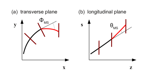
Here and in the following we assume that tracks are measured in a homogeneous magnetic field where trajectories of charged particles are described by helices. Seven parameters are needed to describe a helix from a start to an end-point111The parameters are: the start point (3), the direction (2), the curvature (1) and the length of the helix (1).. Therefore, in order to reconstruct the track parameters at least three space points are needed which have to be measured. If solid state tracking detectors are used a complication arises from MS. Because of deflection at the middle space point (detector layer) two helices are needed to describe the trajectory, see figure 1. The connected helices are then described by parameters. Only ten parameters are needed if the momentum, and correspondingly the 3D track radius (inverse of the 3D curvature ), do not change222This is typically a very good assumption for thin silicon sensors.. Two of the ten parameters are the multiple scattering angles at the middle layer in the transverse plane and longitudinal plane .333 The longitudinal plane is defined as - plane with being the 3D-track length and the direction parallel to the magnetic field.. With three hit coordinates, however, only nine parameters can be determined, thus one parameter remains undefined. Note that hit uncertainties have been neglected so far.
A solution to this problem comes from scattering theory which says that the average scattering angle vanishes. The RMS of the scattering angle distribution is given by with being the particle momentum and the material thickness in units of the radiation length . In the following we use the Highland formula as given by the Particle Data Group [7]. By adding two constraints from the expected scattering distribution and assuming energy conservation the two helices can now be fitted. The general solution of this triplet fit, which can be found by a linearisation ansatz [8], can be directly calculated from the coordinates of the three hit positions.
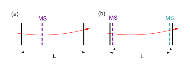
Now we turn to the question which detector design, if MS dominates, provides the best track (momentum) resolution for a given distance between the first and last hit point, see figure 2 (a). For the relative momentum resolution we obtain:
| (1) |
with being an effective scattering parameter describing the thickness of material at the middle hit position and the magnetic field strength.444Here we assume no material between the sensor layers. Note that spatial the resolution is independent of the relative position of the middle layer with respect to the first and last layer. Using (1), it is easy to prove that for given and dominating MS uncertainties the best track measurement is obtained for a configuration with four layers as shown in figure 2 (b) where two closely stacked pairs of layers are used. For this configuration one obtains:
| (2) |
providing a factor reduction in resolution compared to any three-layer configuration. This reduction comes here from the combination of the two triplet measurements which are statistically independent (two different scattering layers). Also note that the relative momentum resolution is momentum independent as long as multiple scattering dominates and non-linear geometrical effects from bending can be neglected.
3 Optimal detector geometry and multiple scattering
Above we have discussed optimal geometries for spectrometers considering MS. But why should we discuss MS for a search machine like LHC where mostly high momentum particles exhibiting low MS are used for triggering and new physics searches? The answer is simple; most particles produced at LHC have small transverse momentum GeV, and low momentum tracks are responsible for the hit combinatorial problem which is the main complication for (fast) track reconstruction especially at high luminosities (pile-up). Therefore, MS has to be considered for an optimised tracker layout.
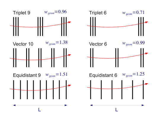
In figure 3 different types of detector geometries are shown which are studied in more detail in the following sections. For the simulation we assume an axial-symmetric tracking detector. The layer planes in figure 3 refer to the relative radial positions. For each of the different geometries we can parameterise the relative momentum resolution if MS dominates as:
| (3) |
where a generalised geometry factor is introduced. We consider three classes of detector types: geometries with equidistant layer spacing, geometries with closely stacked doublet layers and geometries with closely stacked triplet layers. The design with doublet layers are also referred to as “vector” as they allow to measure the direction of the particle at each doublet layer. For all geometries the parameters, as calculated from scattering theory, are given. They are calculated for small curvatures and infinitesimally small distances between stacked layers. Theoretically, the “Triplet6” geometry provides the best resolution. This can be easily understood as it approaches the optimal design of figure 2 (b) for infinitesimal stacking. It is interesting to note that equidistant designs have the worst resolution if MS dominates and that the relative momentum resolution scales as if the number of layers is large.
4 Track parameter resolution study
A Monte Carlo simulation is used to study for the different geometries the resolution of the reconstructed track parameters: the azimuthal angle , the polar angle , the track radius , and the distance of closest approach to the origin in the transverse plane and in the longitudinal plane . For the simulation we leave the inner detector region un-instrumented and place the first layer at a radius of cm and the last layer at cm. The distance between stacked layers is chosen to be cm for both vector and triplet layers. Minimum bias events are generated and the track parameters resolutions are studied in the central detector region 555 is the pseudorapidy of the track. . We use a magnetic field of T and set the material thickness per layer to radiation length, resulting in a material parameter of Tm.
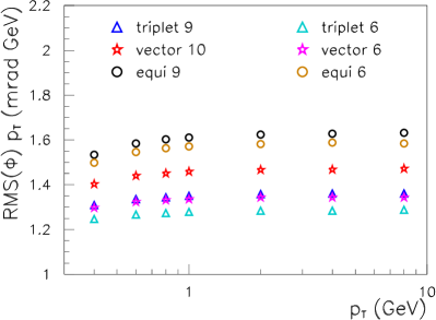
The largest differences between the studied geometries are seen in the resolution and in the momentum resolution. In figure 4 (a) the RMS of the -normalised resolution is shown as function of the track using the MS-fit. Note that the fit consists of many helix parameterisations. In general, designs with large gaps between the layers provide a better resolution. The triplet tracking design with six layers has about better resolution than the equidistant 9-layer design.
In figure 4 (b) the RMS of the relative momentum resolution is shown for two different fits: the MS-fit and a global helix fit [9] where all hits are fitted by an unique helix parameterisation. In addition to MS, hit position uncertainties are also simulated here using a hit resolution of m (corresponding to a pixel size of ). At low momentum, where MS effects dominate, the MS-fit gives the best momentum resolution and the triplet layer designs are superior compared to the equidistant designs. With increasing the resolution obtained by the global helix fit is rather constant whereas the resolution of the MS-fit gets worse, in general. A cross over point can be defined where the results of the MS-fit and the global helix fit are comparable. For the triplet designs and vector designs (not shown) the cross over point is in the GeV region whereas for the equidistant designs the cross over point is at GeV. This can be easily understood; for stacked layers with small layer spacings the angular uncertainty of each track segment, , is much larger than for designs with equidistant spacing and large gaps between the layers. Therefore, hit uncertainties in designs with stacked layers affect the momentum resolution at much lower -values. For tracks with GeV both multiple scattering effects and hit uncertainties have to be included for a proper track fit. Such combined fits are performed by, for example, Kalman filters [10] and General Broken Line fits [11]. At very high momentum, GeV, (not shown in the figures) MS effects are negligible, and the equidistant and stacked layer designs show a very similar performance.
To summarise, about of all particles at LHC are of low momentum. Low tracks for which MS dominates can be best measured with an optmised tracker design with large gaps between sensor layers and a minimum number of layers. These tracks are most efficiently reconstructed using triplet fits.
5 Track linking study
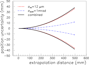
Track linking is the most time expensive step in the track reconstruction. Usually, a track seed is needed which is then extrapolated to the next layers. A seed can either be defined by a pair of hits (3D space points) plus an additional constraint, for example that the particle originates from a collision point or beamline, or by a hit triplet which already defines a track, see section 2. Hit triplets are especially easy to find in a pixel tracker with triplet layers. For not too low transverse momenta all three hits of a triplet can be roughly connected by a straight line. The relatively low occupancy in pixel detectors makes it very easy to find such triplet seeds. Next, the question arises how well we can extrapolated the trajectory from the last layer of a seed to the next (more far distant) sensor layer? Figure 5 shows the envelopes of the extrapolated trajectories from a hit triplet with a hit distance of cm.
The envelopes are shown separately for the transverse and longitudinal plane. In the transverse plane the envelope grows quadratically with the extrapolation distance and reaches about cm after cm extrapolation distance. In contrast, in the longitudinal plane the envelope is only of sub-millimeter size at the same extrapolation distance. We can conclude from this study that for efficient track linking a high -resolution of the detector is much more important than a good resolution in the - plane. 666 A very good resolution in the - plane is still required for the momentum measurement, of course. This strongly motivates to use pixel detectors instead of strips!
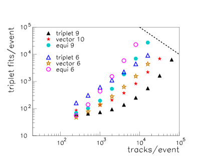
In a next step we study the track linking performance for the different geometries of figure 3. We use two “figures of merit” to measure the performance: (A) the number of triplet fits needed to validate hit combinations777The global track fit of hits consists of triplet fits. in the linking procedure and (B) the relative number of tracks containing hit ambiguities where hits are potentially assigned to more than one track. A link is defined to be valid if a minimum -cut is fulfilled. The -cut is chosen such that of the generated tracks are reconstructed. The simulation and the track fit include multiple scattering and hit uncertainties. Figure 6 (a) shows the number of triplet fits used for the linking as function of the number of tracks per event. Large differences can be seen for the different detector geometries. For the upgraded LHC accelerater about 1000-2000 charged tracks are expected in the central region. The “triplet 9” design shows an outstanding performance compared to the other geometries: less than 100 triplet fits/track are required for 1000 tracks/event whereas for all other geometries significantly more fits are required. The “triplet 9” geometry is the only one where events with even 64000 tracks can be completely reconstructed in reasonable time. 888 Reasonable time is here defined by fits. A single fit on a GPU takes about ns [5].
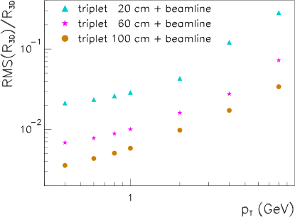
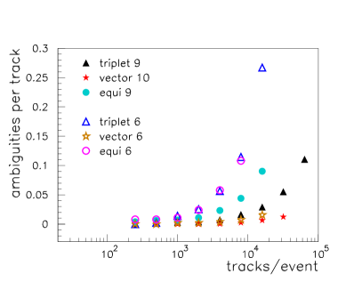
Figure 6 (b) shows the relative number of tracks with at least one hit ambiguity, which occurs when a hit can be assigned to more than one track. Note that a large fraction of the ambiguities could in principal be resolved using arbitration algorithms. However the goal of this study is to quantify the possible fake rate, and no effort is made to resolve ambiguities here. We can see that all vector tracker designs and the “triplet 9” design have the lowest rate of hit ambiguities. In general, all designs show a very good performance for track multiplicities of 1000-2000 per event (LHC-upgrade). From these studies we conclude that pixel tracker geometries are very robust and allow to reconstruct events with very high track multiplicities at high rate.
6 Triplet trigger layers
In the studies discussed so far we have seen that the “triplet9” design consisting of three groups of stacked triplets layers gives overall the best performance in terms of track linking and track resolution. Since a single triplet is sufficient to measure track parameters we study here the simple possibility to use triplet layers for track triggering. Compared to designs where sensor layers are spatially separated, stacked layers provide the opportunity to correlate hit information between nearby layers and to form a trigger decision [12, 13].
With a single hit triplet all track parameters can be reconstructed at once and the trajectory can be extrapolated to the beam-line or the calorimeter. In a first step, the very good pointing resolution in the longitudinal plane and the moderate resolution in the transverse plane (figure 5) allows to cross check the primary particle hypothesis that is the track originates from the primary vertex. This and the high redundancy in the triplet reconstruction signficantly reduces the fake rate compared to vector tracking designs where the vertex constraint has to be used for the track reconstruction. In a second step, the track resolution can be further improved by applying the primary vertex constraint. The resulting relative momentum resolutions for hit triplets positioned at radii cm are shown in figure 7. Tracks with GeV are reconstructed with a resolution of about 1%(10%) if the hit triplet is placed at cm. Such a resolution is considered to be more than sufficient for a track trigger.
7 Hardware realisation
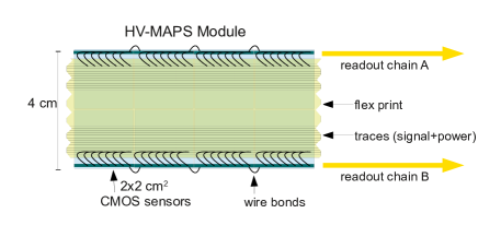
The construction of an all-pixel detector for a LHC-experiment is certainly a big challenge in terms of radiation hardness, power, cooling, mechanics, and so on. Preliminary results, however, indicate that the HV-MAPS technology might fulfill all these requirements [14, 5], and a design proposal based on this technology including a track trigger option is presented here. Figure 8 shows a section of a cm wide module composed of cm2 HV-MAPS sensors. About of the sensors surface is active and small inactive edges contain the readout logic and drivers. Electrical connections for power, control, monitoring and hit signals are made via wire bonds. Connections can be done either between adjacent sensors, or between sensors and multilayer flexprints which are glued directly on the sensors and read out at one end of the ladder. Mechanical stability is ensured by gluing the sensors on a carbon-foam structure which also embeds cooling functionalities. The readout of a module can be organised by several readout chains. Hits are read out after discrimination, digitisation and zero suppression continuously via high speed LVDS links, of which several can be operated in parallel.
The data rate of a module of m length positioned at a radius of cm is expected to be about Gbit/s for upgraded LHC luminosities of . Such data rates could be handled by a fast front-end processor, located at the end of the ladders, which searches online for hit-triplets. By using the geometry shown in figure 8 (b), hit coincidences between three stacked layers can be detected with high acceptance, and a trigger decision signalling for example high momentum tracks can be formed.
8 Summary
Various aspects of a new tracking concept based on hit triplets are discussed for future high rate experiments. The focus is put on MS-dominated tracks, relevant for hadron colliders where most tracks are at low momentum. At least three layers of pixel detectors are needed for track reconstruction, and a fast triplet fit based on MS is introduced. Different types of detector geometries are studied and optimal designs with emphasis on low momentum tracks are presented. A design consisting of three groups of triplet layers shows the best reconstruction performance in terms of speed. It is shown that at high particle rates pixel detectors provide a very good track reconstruction performance and low fake rate. Hit triplets can also be used for track triggering, and a design of an all-pixel tracking detector based on the HV-MAPS technology is presented. By using triplet layers in the outer region of a tracking detector, track triggers could be realised at the upgraded high luminosity LHC experiments. Such a trigger would be able to reconstruct all tracks originating from pp interactions for every collision. More detailed simulations are required to study the trigger rates and efficiencies of this concept.
9 Acknowledgements
I would like to thank I. Peric and D. Wiedner for many inspiring discussions on the “all-pixel tracker” idea and N. Berger, M. Kiehn and A. Kozlinskiy for discussing track reconstruction issues.
References
- [1] I. Peric, A novel monolithic pixelated particle detector implemented in high-voltage CMOS technology, Nucl.Instrum.Meth. A582 (2007) 876.
- [2] I. Peric and C. Takacs, Large monolithic particle pixel-detector in high-voltage CMOS technology, Nucl.Instrum.Meth. A624 (2010) 504.
- [3] S. Shreshta, The High-Voltage Monolithic Active Pixel Sensor for the Mu3e Experiment in proceedings of Technology and Instrumentation in Particle Physics 2014, June, 2–6, 2014, Amsterdam, the Nederlands. To be published in Proceedings of Science.
- [4] A. Blondel et al., Research Proposal for an Experiment to Search for the Decay , research proposal, Paul Scherrrer Institut, Switzerland, January 2013. [arXiv:1301.6113]
- [5] A. Kozlinskiy, Track Reconstruction for Mu3e based on a Multiple Scattering Fit, in Workshop on Intelligent Trackers 2014, May 14th-16th 2014, University of Pennsylvania, USA.
- [6] N. Berger et al., A tracker for the Mu3e experiment based on high-voltage monolithic active pixel sensors, Nucl.Instrum.Meth. A732 (2013) 6-65.
- [7] J. Beringer et al. (Particle Data Group), Phys. Rev. D86 010001 (2012).
- [8] A. Schöning et al., A Multiple Scattering Triplet Fit for Pixel Detectors, publication in preparation.
- [9] V. Karimäki, Effective circle fitting for particle trajectories, Nucl.Instrum.Meth. A305 (1991) 187.
- [10] R.E. Kalman, A New Approach to Linear Filtering and Prediction Problems, Transactions of the ASME–Journal of Basic Engineering, volume 82 (1960) 35-45.
- [11] C. Kleinwort, General Broken Lines as advanced track fitting method, Nucl.Instrum.Meth. A673 (2012) 107-110.
- [12] M. Garcia-Sciveres et al., System concepts for doublet tracking layers \jinst52010C10001.
- [13] J. Bernardini et al., Design and development of micro-strip stacked module prototypes to measure flying particle directions \jinst52010C07014.
- [14] I. Peric et al., High-voltage pixel detectors in commercial CMOS technologies for ATLAS, CLIC and Mu3e experiments Nucl.Instrum.Meth. A731 (2013) 131-136.