Bipolar switching in an orthogonal spin transfer spin valve device
Abstract
We demonstrate current-induced bipolar switching in in-plane magnetized spin-valve devices that incorporate a perpendicularly magnetized spin polarizing layer. Further, hysteretic transitions into a state with intermediate resistance occur at high currents, again for both current polarities. These transitions are shown to be consistent with a macrospin model that considers a spin-polarized current that is tilted with respect to the free layer’s plane, due to the presence of spin-transfer torque from the polarizing layer. These unique switching characteristics, which have their origin in the non-collinear layer magnetizations, are of interest for magnetic random access memory and spin-torque oscillator devices.
I Introduction
Spin transfer torque (STT) devices continue to be intensively studied both for their potential to realize current controlled devices, such as magnetic memory and oscillators, and for fundamental interest in the nature of current induced magnetic excitations Brataas et al. (2012). A prototypical STT device consists of two magnetic layers separated by a non-magnetic layer, either a metal, forming a spin-valve or a thin insulating layer, forming a magnetic tunnel junction (MTJ). One of the magnetic layers can be excited by spin-torques, while the other is fixed. A defining characteristic of such devices is that for a set initial state (e.g. the layer magnetizations aligned either parallel or antiparallel) current induced switching only occurs for one current polarity Katine et al. (2000). Another characteristic of such devices is that the spin-transfer torques are small when the layers are nearly collinearly magnetized leading to stochastic switching (see, for example, Liu et al. (2014)).
Here we consider STT devices that incorporate an orthogonally magnetized spin-polarizing layer in an in-plane magnetized spin-valve, known as orthogonal spin-transfer (OST) device Kent et al. (2004). A polarizing layer that is magnetized perpendicular to the free layer can significantly improve write speed and energy efficiency of STT-magnetic random access memories Liu et al. (2010); Nikonov et al. (2010); Lee et al. (2011); Rowlands et al. (2011); Liu et al. (2012); Park et al. (2013); Ye et al. (2014) by providing a large initial spin-transfer torque (i.e. a large torque the moment a current is applied). An OST device can also function as a microwave oscillator, because the polarizer can produce precessional magnetization dynamics, with the free layer precessing out of the film plane about an axis normal to the layer planes Houssameddine et al. (2007); Ebels et al. (2008); Firastrau et al. (2008). This precessional motion also can be used for ultrafast magnetization switching. For instance, sub-nanosecond switching has been observed in OST-MTJ devices that incorporate a perpendicularly magnetized polarizing layer Liu et al. (2010); Rowlands et al. (2011); Liu et al. (2012). Further, for nanosecond pulses the switching has been observed to be bipolar and to induce magnetization precession Liu et al. (2010, 2012). However, deterministic bipolar switching between P and AP states has not been observed in quasistatic measurements. Further, the effect of applied fields on these current-induced switching thresholds has not been reported or considered in model studies.
Here we report the observation of bipolar switching of OST spin valve devices, where in contrast to conventional collinearly magnetized SV devices, the switching from parallel (P) to antiparallel (AP) resistance states and the reverse transition (AP to P) occurs for both current polarities in a range of applied fields. Further, we find hysteretic transitions into an intermediate resistance state (IR) at large current, with the IR state persisting to currents less than the threshold currents for P to AP and AP to P switching. A macrospin model, including spin transfer torques from the reference and polarizing layers as well as finite temperature effects, captures the hysteretic current-driven transitions observed in experiment.
II Experiment
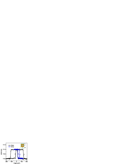
The layer stacks consist of a perpendicularly magnetized spin-polarizing layer, a non-magnetic metallic spacer layer, a free magnetic layer followed by another non-magnetic metallic spacer layer and a reference magnetic layer, as illustrated in the inset of Fig. 1. The polarizer consists of a Co/Pd and Co/Ni multilayer, with the Co/Ni multilayer closest to the free layer (FL), providing a highly spin-polarized current Liu et al. (2010). The FL is a 3 nm thick CoFeB layer. The full layer stack is 6.2 [Co/Pd][Co/Ni]/10 Cu/3 CoFeB/10 Cu/12 CoFeB, with the layer thicknesses indicated in nanometers. The stack was patterned into nanopillar devices with various shapes and sizes using e-beam lithography and ion-milling. Here we present results on 50 nm 100 nm devices in the shape of an ellipse. The magnetic easy axis of free layer is in the film plane along the long axis of ellipse due to magnetic shape anisotropy. Shape anisotropy also sets the magnetization direction of the nm thick CoFeB reference layer (RL).
Figure 1 shows measurements of the differential resistance () as a function of applied field along the easy axis. The measurements are made with a lock-in amplifier using an ac current of A at a frequency of Hz. A field sweep from mT to mT (major hysteresis loop) shows steps in resistance of indicative of switching of the FL from P to AP relative to the RL. The coercive field of the RL is about mT. A minor loop ( mT to mT) shows the switching of only the FL. The change in resistance between P and AP states is . The coercive field for AP to P FL transitions is mT and the coercive field for P to AP FL transitions is mT. The minor loop is centered at mT due to dipolar coupling between the FL and RL. Thus an external field of corresponds (on average) to zero effective field applied to the FL.
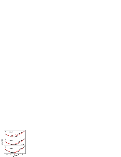
Current induced switching was characterized by measuring the differential resistance as a function of current for a series of easy axis applied fields. The magnetic state (P or AP) is first set by applying a large magnetic field mT and then a lower field ( mT for the P state, mT for the AP state). Then the current was slowly ramped ( mA/s) from to mA and then ramped back to mA, with versus recorded at each measuring field. Positive current corresponds to electron flow from polarizing to the reference layer (from bottom to the top of the layer stack represented in the inset of Fig. 1). In this case the spin-torque associated with the RL spin-torque favors an AP state for positive current. Representative measurement results starting from the P state are shown in Fig. 2. Similar results were found in measurements starting from the AP state, which are discussed below.
In Fig. 2(a) as the magnitude of the current is increased (black curves), there is a discrete increase in differential resistance of , associated with a P to AP transition. This is seen to occur for both polarities of the current. On further increasing the current there is a change in resistance of about half of , i.e. a transition into an intermediate resistance state (IR). On decreasing the current (red curves) the resistance eventually returns to that of the device’s AP state. Near zero effective applied field (), P to AP switching is only seen at positive current polarity (Fig. 2 (b) and (c)). Whereas, for negative current, only P to IR transitions occur as the current is increased. When the magnitude of the current is decreased, there is a transition from an IR state to an AP state for applied magnetic fields smaller than mT) and to a P state for fields larger than .
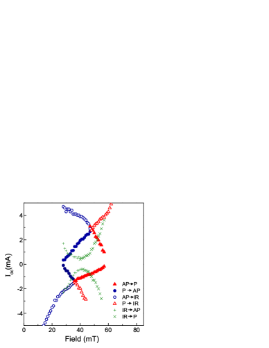
This seemingly complex switching behavior can be summarized by plotting the threshold currents for switching between resistance states in a current-applied field state diagram (Fig. 3). Each symbol in this diagram corresponds in a discrete change in the resistance. The solid symbols represent resistance changes of corresponding to transitions between P and AP states. They form a diamond-shaped central zone within which both P and AP states are possible. When the current is greater than mA or is less than mA, the step change in resistance is less than . The boundaries are labeled by open symbols and correspond to P and AP to IR transitions. These boundaries meet and join the P to AP transition boundaries. Further, they define two triangular zones that encompass IR states at high current magnitudes (both for positive and negative current polarities). As the current is swept back to zero, two parabolic shaped curves (green) show the IR to P or AP transitions.
The general features of the state diagram of an OST-SV device are the following: (1) For magnetic fields near the FL coercive fields ( and ), current induced switching is bipolar. For fields close to but less than , AP to P transitions occur for both positive and negative currents and for fields near but greater than , P to AP transitions occur for both current polarities. (2) Near , the center of the FL’s hysteresis loop, the switching occurs for only one current polarity, positive current for the P to AP transition and negative current for the AP to P current. (3) At large currents, transitions into an IR state are observed and this state persists even as the current is reduced well below the threshold current for P/AP transitions. These features were seen in all ten nm nm ellipse devices that we studied.
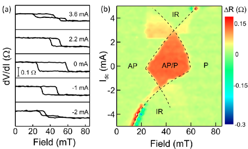
The device states can also be determined by measuring the differential resistance as a function of field at constant current. This is shown in Fig. 4. Fig. 4(a) shows representative hysteresis loops at several currents. At zero dc current the coercive field () of the FL is largest and the coercive field decreases as the current magnitude increases. For currents greater than mA or less than mA, a plateau at a resistance between that of the P and AP state resistances is seen, with the field range of the plateau increasing with current magnitude.
A field swept state diagram is constructed as follows. The resistance measured with decreasing field is subtracted from the resistance measured with increasing field. The resistance difference is then plotted on a color scale versus current and field (Fig. 4(b)). is nonzero only in field ranges in which the device response is hysteretic. The boundaries between zero and and non-zero regimes are the boundaries between the P, AP and IR states. Thus the same general switching characteristics are observed in both current and field swept measurements.
III Model
To understand the device switching characteristics, we consider the spin-transfer torques acting on the FL along with its magnetic anisotropy in a macrospin model. The dynamics of , a unit vector in the magnetization direction of the free layer (), is given by the Landau-Lifshitz-Gilbert-Slonczewki (LLGS) equation:
| (1) |
where represents the LLG, thermal torque and spin-torque. The LLG torque is given by , with effective field , volume of the magnetic element and damping constant . Time in Eqn. 1 has been normalized by the precession frequency, (i.e. ), where is the gyromagnetic ratio. The thermal torque is induced by a Gaussian distributed random field Pinna et al. (2013). The FL has a biaxial magnetic anisotropy energy:
| (2) |
with an easy axis along and hard axis along , where is the ratio of the hard to easy axis anisotropy and is the energy barrier to magnetization reversal.
Spin-torque contributions due to both the polarizer (magnetized out-of-the film plane, along ) and RL (magnetized in the film plane, along ) can be described in terms of effective spin-polarization direction that is tilted with respect to the plane:
| (3) |
Here and are the spin polarizations and spin-torque asymmetry parameters for the RL and OP, respectively. is a normalized applied current. Therefore, the combined spin-torque acting on the FL magnetization can be written as:
| (4) |
where the orientation of the effective spin-polarization axis is tilted with respect to the in-plane (IP) direction by an angle with
| (5) |
Naturally, in the case of (no out-of-plane polarizer), will reduce to the conventional collinear spin-torque expression and will lie in plane.
A qualitative understanding of central zone of the state-diagram can be seen from the form of the spin-transfer torque in Eqs. 3. The torque associated with the reference layer is initially collinear with the damping torque. It thus leads to switching via the antidamping mechanism, typical of spin-transfer devices with collinear magnetizations. However, the spin-transfer torque from the polarizer () is equivalent to an effective field in the direction , which is initially in the direction of the FL’s medium axis . Such a field reduces the FL’s easy axis coercive field (for both current polarities), as is the case in the Stoner-Wohlfarth model with a medium axis magnetic field. In the Stoner-Wohlfarth model the result is an astroid shaped switching boundary, which resembles the diamond shaped bistable central zone of our state diagram.
More quantitatively, the spin-torque asymmetry parameters lead to torques that depend on the magnetization state of the FL. For example, different current magnitudes are typically necessary for AP to P and P to AP switching Slonczewski (1996). Generally, larger currents are needed for P to AP switching at the same field, as seen in the state diagram (Fig. 3). For simplicity in our model, we consider , as is typically small during the switching process. Therefore, accounts for the main asymmetries we observe in spin-torque switching.
We study the switching by simulating an ensemble of 5000 macrospins under the influence of spin-torque, thermal noise and an applied field. The ensemble is initially taken to be thermalized in one of its (two possible) equilibrium easy-axis states before a current is applied. After a current is applied the ensemble reaches a new steady-state configuration over the course of a microsecond. The simulation is then repeated at a higher current in incremental steps using the steady-state ensemble of the previous current as the initial condition. Upon reaching the limit of our current range, we incrementally reduce the current to reproduce the procedure in the current swept experiments.
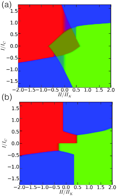
Simulation results are plotted in Fig. 5 both for current ramped-up (a), and current ramped-down (b) cases, with parameters determined as follows. is governed by magnetic shape anisotropy and is calculated based on the FL’s shape to be . The spin-torque asymmetry is taken to reproduce the measured ratio of positive to negative switching currents at effective zero field , giving . is estimated to be J (i.e. , with K), taking and mT. We then ran simulations with spin torque ratios and . The results are shown as a colormap where red and green represent in-plane AP/P configurations and blue corresponds to IR states. Fig. 5 shows results for . (Results for the other spin-torque ratios studies are shown in the Supplementary Materials.) Depending on the proportions in which the ensemble is partitioned between the three available states, bistability regions arise and are represented by a superposition of the colors, an example being the dark yellow (green+red) P/AP bistability region at the center of the state diagram. The magnetic field is normalized to and current is normalized by the positive critical current at zero temperature. The normalized critical current (, ) and coercive field (, ) are smaller than 1 because of thermal fluctuations.
The simulation captures the main switching features observed in the experiment both for current ramping up and down. First, we observe a distorted diamond shaped central P/AP bistable central zone (Fig. 5(a)), which shows bipolar switching near the layer’s coercive field. The distortion (e.g. the lower switching current for AP to P transitions) is associated with the non-zero spin-torque asymmetry parameter . Second, there are transitions into an out-of-plane precessional state which we associate with the IR state we observe experimentally. We find that the threshold current for P/AP to IR transitions is higher when the current is increasing than the IR to P/AP transitions when the current is decreasing (Fig. 5(b)), as observed in experiment. The vertical boundaries in Fig. 5(b) are artifacts that result from not having applied large enough currents to realize an IR state when the current was increasing. In this case, when decreasing the current, the ensemble appears to not transition out of its initial AP or P configuration. Deviations between the experiment and macrospin model appear at large currents. For example, the curvature of the AP to IR switching boundary is positive in the simulation but negative in the experimental data. This indicates that more sophisticated models, such as micromagnetic models, of the magnetization dynamics may be needed to explain the large current dynamics.
The hysteretic transitions to the IR state can be understood in a recent analytic theory which examined the influence of the spin-torque ratio () on the magnetization dynamics Pinna et al. (2013, 2014). The theory considered a zero field case in the absence of spin-torque asymmetries (i.e. , ). A key result was that for spin-polarization tilts () larger than a critical value there are hysteric transitions into a stable out-of-plane precessional (OOP) state. The condition is . In this case a critical threshold current exists above which an OOP orbit is stable. However, a larger current must be applied to establish an OOP state starting from a P or AP state. This analytic theory thus predicts the hysteretic transition between IR and P/AP states that are observed in this experiment and also shows the material parameters that determine the magnitude of the hysteresis.
IV Summary
In summary, we have systematically studied current-induced transitions in OST-SV devices and determined a field-current state-diagram for these transitions, which involve switching between three different resistance states, P, AP and IR. Deterministic bipolar switching between P and AP states is observed in a range of fields near the FL coercive field, resulting in a distinct diamond shaped AP/P bistable state regime in field-current state-diagram. The main features are understood in a macrospin model that considers the effective spin-torque acting on the free layer as a superposition of the torques from the OP and RL. This simple model thus provides guidance in understanding and optimizing the switching characteristics of OST-devices. These results also show the unique spin-transfer switching characteristics of devices with non-collinear magnetizations.
Acknowledgements
This research was supported by NSF-DMR-1309202 and in part by IARPA and SPAWAR contract N66001-12-C-2019.
References
- Brataas et al. (2012) A. Brataas, A. D. Kent, and H. Ohno, “Current-induced torques in magnetic materials,” Nature Materials 11, 372 (2012).
- Katine et al. (2000) J. A. Katine, F. J. Albert, R. A. Buhrman, E. B. Myers, and D. C. Ralph, “Current-driven magnetization reversal and spin-wave excitations in Co/Cu/Co pillars,” Physical Review Letters 84, 3149–3152 (2000).
- Liu et al. (2014) H. Liu, D. Bedau, J.Z. Sun, S. Mangin, E.E. Fullerton, J.A. Katine, and A.D. Kent, “Dynamics of spin torque switching in all-perpendicular spin valve nanopillars,” Journal of Magnetism and Magnetic Materials 358-359, 233 – 258 (2014).
- Kent et al. (2004) A. D. Kent, B. Ozyilmaz, and E. del Barco, “Spin-transfer-induced precessional magnetization reversal,” Applied Physics Letters 84, 3897–3899 (2004).
- Liu et al. (2010) H. Liu, D. Bedau, D. Backes, J. A. Katine, J. Langer, and A. D. Kent, “Ultrafast switching in magnetic tunnel junction based orthogonal spin transfer devices,” Applied Physics Letters 97, 242510 (2010).
- Nikonov et al. (2010) Dmitri E. Nikonov, George I. Bourianoff, Graham Rowlands, and Ilya N. Krivorotov, “Strategies and tolerances of spin transfer torque switching,” Journal of Applied Physics 107, 113910 (2010).
- Lee et al. (2011) O. J. Lee, D. C. Ralph, and R. A. Buhrman, “Spin-torque-driven ballistic precessional switching with 50 ps impulses,” Applied Physics Letters 99, 102507 (2011).
- Rowlands et al. (2011) G. E. Rowlands, T. Rahman, J. A. Katine, J. Langer, A. Lyle, H. Zhao, J. G. Alzate, A. A. Kovalev, Y. Tserkovnyak, Z. M. Zeng, H. W. Jiang, K. Galatsis, Y. M. Huai, P. Khalili Amiri, K. L. Wang, I. N. Krivorotov, and J.-P. Wang, “Deep subnanosecond spin torque switching in magnetic tunnel junctions with combined in-plane and perpendicular polarizers,” Applied Physics Letters 98, 102509 (2011).
- Liu et al. (2012) H. Liu, D. Bedau, D. Backes, J. A. Katine, and A. D. Kent, “Precessional reversal in orthogonal spin transfer magnetic random access memory devices,” Applied Physics Letters 101, 032403 (2012).
- Park et al. (2013) Junbo Park, D. C. Ralph, and R. A. Buhrman, “Fast deterministic switching in orthogonal spin torque devices via the control of the relative spin polarizations,” Applied Physics Letters 103, 252406 (2013).
- Ye et al. (2014) L. Ye, D. B. Gopman, L. Rehm, D. Backes, G. Wolf, T. Ohki, A. F. Kirichenko, I. V. Vernik, O. A. Mukhanov, and A. D. Kent, “Spin-transfer switching of orthogonal spin-valve devices at cryogenic temperatures,” Journal of Applied Physics 115, 17C725 (2014).
- Houssameddine et al. (2007) D. Houssameddine, U. Ebels, B. Delaët, B. Rodmacq, I. Firastrau, F. Ponthenier, M. Brunet, C. Thirion, J-P. Michel, L. Prejbeanu-Buda, M.-C. Cyrille, O. Redon, and B. Dieny, “Spin-torque oscillator using a perpendicular polarizer and a planar free layer,” Nature Materials 6, 447–453 (2007).
- Ebels et al. (2008) U. Ebels, D. Houssameddine, I. Firastrau, D. Gusakova, C. Thirion, B. Dieny, and L. D. Buda-Prejbeanu, “Macrospin description of the perpendicular polarizer-planar free-layer spin-torque oscillator,” Phys. Rev. B 78, 024436 (2008).
- Firastrau et al. (2008) I. Firastrau, D. Gusakova, D. Houssameddine, U. Ebels, M.-C. Cyrille, B. Delaet, B. Dieny, O. Redon, J.-Ch. Toussaint, and L. D. Buda-Prejbeanu, “Modeling of the perpendicular polarizer-planar free layer spin torque oscillator: Micromagnetic simulations,” Phys. Rev. B 78, 024437 (2008).
- Pinna et al. (2013) D. Pinna, A. D. Kent, and D. L. Stein, “Thermally assisted spin-transfer torque dynamics in energy space,” Phys. Rev. B 88, 104405 (2013).
- Slonczewski (1996) J. C. Slonczewski, “Current-driven excitation of magnetic multilayers,” Journal of Magnetism and Magnetic Materials 159, L1–L7 (1996).
- Pinna et al. (2014) D. Pinna, D. L. Stein, and A. D. Kent, “Spin Torque Oscillators with Thermal Noise: A Constant Energy Orbit Approach,” ArXiv e-prints (2014), arXiv:1405.0731:1405.0731 [cond-mat.mes-hall] .
V Supplementary Material
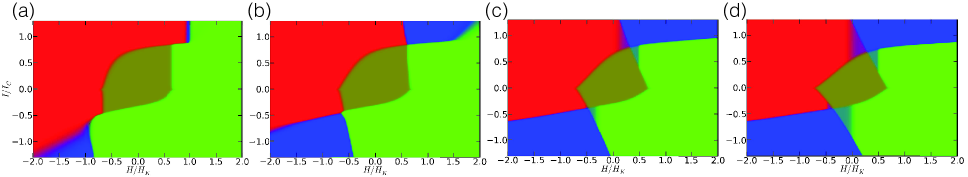
As discussed in the main text, simulations of an ensemble of macrospins were conducted for a range spin torque ratios, . Here we show the effect of varying the spin-torque ratios on the state diagrams and device switching characteristics.
The simulations were done with parameters: , , , mT, T, (i.e. , K) and damping . Results are shown in Fig. 6 for (a) , (b) , (c) and (d) 0.68. As described in the main text, the states AP, P and IR, are indicated in red, green and blue colors respectively. corresponds to no out-of-plane polarizer. The diagram in Fig. 6(a) thus shows the switching boundaries for a purely collinearly magnetized device. There are two vertical switching boundaries and the switching is unipolar: P to AP switching occurs only for positive current while AP to P switching occurs only for negative currents. With increasing spin-torque associated with the out-of-plane magnetized polarizer the initially vertical switching boundaries acquire a negative slope. In case (c) the switching for AP to P and P to AP can now occur for both current polarities in a range of applied fields. The state diagram in (d) with shows the diamond shape we observe in experiment. The results also show that including an out-of-plane polarizer torque leads to a reduced area of the P/AP bistable central zone and also that the switching currents are reduced.