figure \cftpagenumbersofftable
A simple digital system for tuning and long-term frequency stabilisation of a CW Ti:Sapphire laser
Abstract
We have implemented a simple digital system for long-term frequency stabilisation and locking to an arbitrary wavelength of the single-frequency ring CW Ti:Sapphire laser. This system is built using two confocal Fabry-Pérot cavities, one of which is used to narrow short-term linewidth of the laser and the other to improve long-term stability of the laser frequency. The length of the second cavity is stabilised using the radiation from an external-cavity diode laser locked to an atomic transition. Our system is an improvement of a commercial Tekhnoscan laser lock. This system has been successfully used in our experiments on high-resolution laser spectroscopy of ultracold rubidium Rydberg atoms.
keywords:
laser locking, scanning Fabry-Pérot cavity, Rydberg excitationAddress all correspondence to: Ilya I. Beterov, Rzhanov Institute of Semiconductor Physics SB RAS, prosp. Lavrentyeva, 13 630090 Novosibirsk, Russia; Tel: +7 383-333-24-08; Fax: +7 383-333-27-71; E-mail: \linkablebeterov@isp.nsc.ru
1 Introduction
Laser cooling and multiphoton spectroscopy of atoms and molecules commonly require the use of narrow-band frequency stabilised lasers working at various wavelengths. Single-frequency CW Ti:Sapphire lasers with ring cavities are advantageous for laser spectroscopy due to their high power in single frequency and tuneability over a broad spectral range. A variety of techniques have been developed for laser frequency stabilisation needed in many applications in optics and spectroscopy. Typically, the laser output is locked to a highly stable reference cavity or to an atomic transition by means of fringe-side locking [1] or most widely used Pound-Drever-Hall (PDH) technique [2, 3]. Highly-stable Fabry-Pérot cavities commonly use ultra-low expansion (ULE) glass spacers and are temperature-stabilised and kept in vacuum in order to avoid drifts of the resonant frequency induced by temperature and air pressure variations [4, 5, 6]. In such systems, the mirrors cannot be placed on piezo-ceramic transducers (PZT), which feature large frequency drifts of tens of MHz per hour [7]. Therefore, the laser frequency can only be stabilized at a series of fixed values, separated by the free spectral range of the cavity. To overcome this obstacle it is possible to shift the laser frequency using an external acousto-optical modulator or sideband locking technique with electro-optical modulator [8]. Locking the laser to an atomic transition via saturation spectroscopy is commonly used in experiments on atomic spectroscopy and laser cooling. However, this technique is difficult to apply in the case when the desirable laser wavelength does not match the wavelength of available atomic transitions. The same difficulty occurs when the reference cavity is locked to a highly stable reference laser. Another recently developed method is based on the use of a high-precision wavelength meter, which also requires additional reference laser to achieve high accuracy [9].
One of the common experimental demands is multistep excitation of ultracold atoms which requires locking of the laser to a transition between excited atomic states. For two-step excitation it is possible to use the resonances of electromagnetically-induced transparency in a gas cell to lock the lasers [10]. However, generalization of this scheme for three-step laser excitation is technically challenging due to small dipole moments of transitions to Rydberg states and necessity to combine three laser beams in a vapor cell.
We have developed a relatively simple and inexpensive method relying on the digital measurement of the frequency difference between the output of a Ti:Sapphire laser and that of a highly stable diode laser using an auxiliary Fabry-Pérot interferometer. The diode lasers which are locked to an atomic transition between the ground and first excited states of alkali-metal atoms are commonly used in laser cooling experiments. It is important that a single reference laser can be used to lock other lasers to the arbitrary wavelengths.
Essentially, in our locking system the time delay is measured between emergence of transmission peaks coming from the radiation of the Ti:Sapphire laser and from that of the highly stable diode laser as the Fabry-Pérot cavity is scanned.
This method has been successfully implemented in several previous works [11, 12, 13, 14]. A rather complicated analogue electronic detection of transmission peaks in the scanning cavity was first implemented in Ref. [11]. A digital integrator was used to provide the feedback signal to the laser. The frequency drift of the laser did not exceed 1 MHz compared to the reference frequency-stabilised He-Ne laser. In the later works, the electronics for laser stabilisation was substantially simplified by introduction of ADC/DAC modules with a computer control [12, 13, 14]. In Ref. [12] the interference filters were used to individually measure the transmission of multiple laser beams through the cavity, so that several lasers could be locked simultaneously. In Ref. [13] the scanning rate was increased to 1 kHz compared to 200 Hz in Ref. [12] and the transmission signal was sampled at 4 MHz. Increased scanning rate permits frequency locking in a wider bandwidth, but requires faster and more expensive ADC conversion and data analysis. In Ref. [14] the scanning frequency was further raised to 3 kHz and the feedback signal was generated using an analogue peak detector and a fast programmable microcontroller.
Our approach relies on two confocal cavities for line narrowing and long-term frequency stabilisation of the laser. The confocal reference cavity with the mirrors separated by a 10-cm invar spacer is more stable than a long (approximately 70 cm) laser resonator. We use fast analogue locking electronics manufactured by the Tekhnoscan Company (Novosibirsk, Russia) to lock the laser on the reference cavity, and then we only compensate for the long-term drift of the optical length of the reference cavity. This technique allows us to avoid the necessity of using high-speed electronics for peak detection and data analysis, comparing to the previous works [13, 14]. We use a relatively cheap ZetLabTM Zet210 ADC/DAC module (Russia) sampled at 400 kHz for data acquisition and generation of the feedback output voltage, and National Instruments LabViewTM for data analysis.
2 Experiment
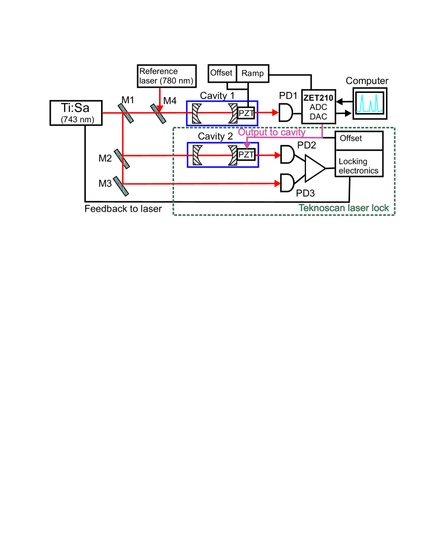
The scheme of our experimental setup is shown in Fig. 1. The radiation of the Ti:Sapphire laser is split by semi-transparent mirror M1 and directed to confocal cavities 1 and 2. The intensity of the light transmitted through the cavities is measured with photodiodes PD1 and PD2. Semi-transparent mirror M2 is used to create a reference laser beam for the side-fringe locking of the Ti:Sapphire laser to a mode of cavity 2 by measuring the difference between the intensities on photodiodes PD2 and PD3 and sending the feedback signal to the laser. This is a part of the commercial Tekhnoscan laser lock. Cavity 2 is a confocal Fabry-Pérot resonator with a 10-cm invar spacer and one of the mirrors mounted on a PZT. The commercially available locking electronics by Tekhnoscan reduces the short-term linewidth of laser radiation to less than 10 kHz. By applying an offset voltage to the PZT of cavity 2, it is possible to tune the laser frequency within the free spectral range of the cavity, which is 750 MHz. The laser frequency drift caused by temperature and air pressure variations, as well as the drift of the PZT, is more than 30 MHz per hour even for the cavity with temperature stabilisation. This does not meet our requirements for experiments with cold Rydberg atoms where resonance widths at laser excitation are less than 5 MHz, and we need to keep the laser on resonance with the atomic transition for tens of minutes.
In order to compensate for this drift, we combine on semi-transparent mirror M4 the radiation of the Ti:Sapphire laser, which is already locked to cavity 2, with the radiation of the reference external-cavity diode laser with wavelength 780 nm, locked to an atomic transition in a rubidium vapour cell via Pound-Drever-Hall technique [2, 3]. The linewidth of this laser was measured by observing the beat spectrum of two identical lasers averaged during 100 ms, and was found to be less than 1 MHz. The radiation of both lasers is send to cavity 1 which is scanned by a triangular signal at 200 Hz from a GW Instek DDS function generator SFG-2004TM. Low-voltage output of the function generator is amplified with a home-built high-voltage amplifier, which drives the PZT. This amplifier also provides additional offset DC voltage to the PZT.
The scanning cavity 1 is a confocal Fabry-Pérot resonator with a 12.5-cm invar spacer corresponding to a free spectral range of MHz. The cavity can be temperature stabilised, however this does not significantly change the performance of the system. The signal from photodiode PD1, which has a bandwidth of 10 MHz, is measured using a commercial ZetLab ZET 210TM ADC/DAC module with maximum sampling frequency of 400 kHz.
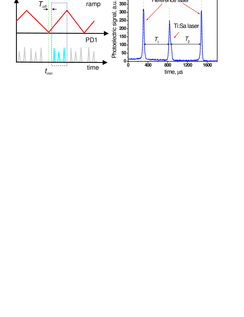
As the signal from photodiode PD1 can only be measured continuously during the period defined by the ADC buffer size of 4096 bytes, we have to use the signal from the function generator, which is measured by a second ADC channel, for synchronization of the data acquisition process. We read the data from the ADC buffer, which contains at least two periods of the synchronisation signal. Then we find the time of the first minimum of the synchronization signal and extract data from a time bin defined by the specified width and offset as shown in Fig. 2(a). Adjustment of the DC offset voltage at the PZT of cavity 1 can be used to tune the positions of the peaks within the window without interrupting the frequency locking process. This is necessary to move the transmission peaks away from the turning points of the ramp signal and to compensate for temperature drift of the cavity in order to keep all the peaks within the measurement window.
The measured time-dependent photoelectric signal on PD1, which is proportional to the transmission of cavity 1, is plotted in Fig. 2(b). We measure the time intervals and between two peaks from the reference laser and the peak from the Ti:Sapphire laser using the Peak Detect virtual instrument implemented in National Instruments LabviewTM, which uses quadratic fit approximation for accurate determination of the peak centers. Then we calculate the ratio:
| (1) |
This ratio depends linearly on the frequency of the Ti:Sapphire laser and ranges between 0 and 1 depending on the relation between the frequencies of the reference laser and Ti:Sapphire laser. We apply a 3-point average filter to an array of measured ratios.
Initially, the Ti:Sapphire laser is locked to cavity 2. By changing the offset voltage on the PZT of this cavity we can tune the laser to any desired wavelength which define the initial ratio of time intervals between the transmission peaks of cavity 1. For long-term stability, we need to minimize the variation . This is achieved by applying an additional voltage to the PZT of cavity 2. The feedback signal is calculated using National Instruments LabviewTM PID toolkit and then converted to voltage via the DAC of the Zetlab ZET 210TM module.
To tune the laser locked to cavity 1, we can manually change the initially set value in the control program during the experiment. The locking system then drives the laser to a newly defined locking point.
3 System performance
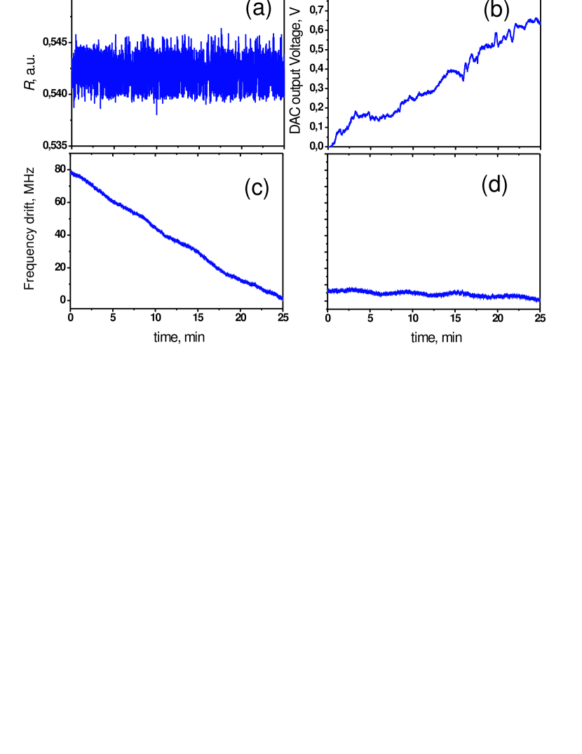
The results of measurement of the ratio of the time intervals R during approximately 20 minutes are presented in Fig. 3(a). The standard deviation of was 0.00115 which corresponds to the error of 0.7 MHz in the determination of the laser frequency. This result is consistent with the previous measurements [11, 12, 13, 14]. The output voltage of DAC, shown in Fig. 3(b), was automatically increased by the locking system from zero to around 0.7 V during the measurement due to the temperature and air pressure variations which affect the optical length of cavity 2, and due to the drift of the PZT of cavity 2.
We have also measured the wavelength of Ti:Sapphire laser output using High FinesseTM WS6 wavemeter. Although this model has limited long-term accuracy (200 MHz error in absolute value), we have used it to study the short-term fluctuations and drifts of the laser frequency. In the mode when the laser was locked to cavity 2 only without temperature stabilisation of the cavity the drift was around 3 MHz per minute [see Fig. 3(c)]. When the laser was also locked to cavity 1 the measured drifts were reduced to 200 kHz per minute [see Fig. 3(d)] which can be attributed to the temperature drift of the wavemeter. Another possible source of error could be the drift of the reference laser, but we have not observed it in the beat spectrum of two identical reference lasers locked to 780 nm.
Our approach is close to the laser locking system described in Ref. [12] where low-frequency data acquisition at 400 kHz had been used along with fully digital data analysis. However, it has been noted in Ref. [12] that their system was unable to compensate for acoustic noises, and it has been proposed to use an additional stable cavity and analog electronics for linewidth narrowing. In our work the laser is locked to cavity 2 by analog electronics via fringe-side locking, which removes the acoustic noises and provides less than 10 kHz rms laser linewidth relative to cavity 2. Our digital locking system compensates only for slow drifts of cavity 2. These are the main differences from the previous work [12].
The limiting factors for the system performance are rather low scanning rate (200 Hz), finesse of cavity 2 (), and stability of the reference laser. Higher scanning rate requires faster sampling, which was not possible with the ADC we used. However, the peak positions fluctuate from scan to scan even for a stabilised laser due to the nonlinearities and hysteresis of the PZT [12]. Therefore we believe that increase of the scanning rate will not substantially improve the performance of our system, and we need to compensate only for slow temperature drifts of cavity 2 and air pressure variations. There is no need to further increase the bandwidth of the locking system by use of high-speed digital electronics, in contrast to previous works [13, 14]. Besides that, for a faster lock, the fluctuations of the peak positions can substantially increase the linewidth of the laser.
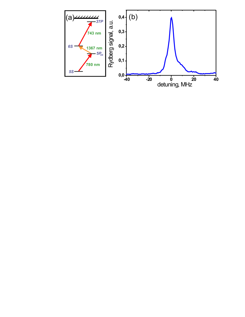
The system performance was good enough to compensate for the long-term drift of cavity 2. We have used this system to lock the Ti:Sapphire laser at 743 nm for three-step laser excitation of cold rubidium atoms into the Rydberg states, as shown in Fig. 4(a) [15, 16]. We used a cooling 780 nm laser diode as a reference source. The typical spectrum of laser excitation of 37 Rydberg rubidium atoms obtained by scanning of the Ti:Sapphire laser by linear ramp voltage applied to cavity 2 is shown in Fig. 4(b). The width of the atomic resonance in our experiment was around 5 MHz. Therefore the stability of our laser lock was good enough for Rydberg excitation of ultracold rubidium atoms.
Acknowledgements.
This work was supported by RFBR grant No. 14-02-00680, by the Russian Academy of Sciences, by EU FP7 IRSES Project ”COLIMA”, and by the Russian Quantum Center.References
- [1] R. L. Barger, M. S. Sorem, and J. L. Hall, “Frequency stabilization of a cw dye laser,” Appl. Phys. Lett. 22, 573 (1973).
- [2] E. D. Black, “An introduction to pound–drever–hall laser frequency stabilization,” Am. J. Phys 69, 79 (2001).
- [3] R. W. P. Drever, J. L. Hall, F. V. Kowalski, J. Hough, G. M. Ford, A. J. Munley, and H. Ward, “Laser phase and frequency stabilization using an optical resonator,” Appl. Phys. B 31, 97 (1983).
- [4] P. Maddaloni, M. Bellini, and P. De Natale, Laser-Based Measurements for Time and Frequency Domain Applications: A Handbook (Series in Optics and Optoelectronics) (CRC Press, 2013).
- [5] Y. Y. Jiang, A. D. Ludlow, N. D. Lemke, R. W. Fox, J. A. Sherman, L.-S. Ma, C. W. Oates, “Making optical atomic clocks more stable with -level laser stabilization,” Nature Photonics 5, 158 (2011).
- [6] T. Kessler, C. Hagemann, C. Grebing, T. Legero, U. Sterr, F. Riehle, M. J. Martin, L. Chen, J. Ye, “A sub-40-mHz-linewidth laser based on a silicon single-crystal optical cavity,” Nature Photonics 6, 687 (2012).
- [7] R. Löw, H. Weimer, J. Nipper, B. Balewski, J. B. Butscher, H. B. Büchler, and T. Pfau, “An experimental and theoretical guide to strongly interacting rydberg gases,” J. Phys. B 45, 113001 (2012).
- [8] J. I. Thorpe, K. Numata, and J. Livas, “Laser frequency stabilization and control through offset sideband locking to optical cavities,” Optics Express 16, 15980 (2008).
- [9] S. Kobtsev, S. Kandrushin, and A. Potekhin, “Long-term frequency stabilization of a continuous-wave tunable laser with the help of a precision wavelength meter,” Appl. Opt. 46, 5840 (2007).
- [10] R. P. Abel, A. K. Mohapatra, M. G. Bason, J. D. Pritchard, K. J. Weatherill, U. Raitzsch and C. S. Adams “Laser frequency stabilization to highly excited state transitions using electromagnetically induced transparency in a cascade system” Appl. Phys. Lett. 94 , 071107 (2009).
- [11] S. M. Jaffe, M. Rochon, and W. M. Yen, “Increasing the frequency stability of singlefrequency lasers,” Rev. Sci. Instrum. 64, 2475 (1993).
- [12] W. Z. Zhao, J. E. Simsarian, L. A. Orozco, and G. D. Sprouse, “A computer-based digital feedback control of frequency drift of multiple lasers,” Rev. Sci. Instrum. 69, 3737 (1998).
- [13] K. Matsubara, S. Uetake, H. Ito, Y. Li, K. Hayasaka, and M. Hosokawa, “Precise frequency-drift measurement of extended-cavity diode laser stabilized with scanning transfer cavity,” Japanese Journal of Applied Physics 44, 229 (2005).
- [14] N. Seymour-Smith, P. Blythe, M. Keller, and W. Lange, “Fast scanning cavity offset lock for laser frequency drift stabilization,” Rev. Sci. Instrum. 81, 075109 (2010).
- [15] D. B. Tretyakov, V. M. Entin, E. A. Yakshina, I. I. Beterov, C. Andreeva, and I. I. Ryabtsev, “Controlling the interactions of a few cold rb rydberg atoms by radiofrequency-assisted Förster resonances,” Phys. Rev. A 90, 041403(R) (2014).
- [16] V. M. Entin, E. A. Yakshina, D. B. Tretyakov, I. I. Beterov, and I. I. Ryabtsev, “Spectroscopy of the three-photon laser excitation of cold rubidium rydberg atoms in a magneto-optical trap,” J. Exp. Theor. Phys. 116, 721 (2013).
Ilya I. Beterov is a senior researcher at the Rzhanov Institute of Semiconductor Physics, Siberian Branch of Russian Academy of Sciences and lecturer at Novosibirsk State University. He received Ph.D. degree from the Institute of Automation and Electrometry Siberian Branch of Russian Academy of Sciences in 2008. His research area is quantum information with Rydberg atoms. He is the author of more than 30 publications in scientific journals.
Asparuh G. Markovski works at the Technical University of Sofia, Bulgaria, at the Faculty of Automation. He received his Ph. D. from the same University in 2004. His major research interests are in the area of Robust Control, Low-cost means for automation, Optimization in the Control Theory.
Sergey Kobtsev is a head of Division of Laser Physics and Innovative Technologies at Novosibirsk State University. He received PhD (1992) and Doctor of Sciences (2010) degrees from the Institute of Automation and Electrometry, Siberian Branch of the Russian Academy of Sciences. His research areas include quantum electronics, fiber and nonlinear optics, high-precision and tunable laser systems. He is the author of more than 200 publications in scientific journals, conference proceedings, and books.
Elena A. Yakshina is a Ph.D. student of Novosibirsk State University. Her major research interest is laser spectroscopy of Rydberg atoms.
Vasily M. Entin is a senior researcher at the Rzhanov Institute of Semiconductor Physics, Siberian Branch of Russian Academy of Sciences. He received his Ph.D. from the Institute of Automation and Electrometry, Siberian Branch of the Russian Academy of Sciences in 2006. His major research interests are laser cooling and laser spectroscopy. He is the author of more than 30 publications in scientific journals.
Denis B. Tretyakov is a researcher at the Rzhanov Institute of Semiconductor Physics, Siberian Branch of Russian Academy of Sciences. He received his Ph.D. from the Institute of Automation and Electrometry, Siberian Branch of the Russian Academy of Sciences in 2008. His major research interests are quantum information with Rydberg atoms and long-range atomic interactions. He is the author of more than 30 publications in scientific journals.
Vladimir Baraulya graduated in 1982 from Novosibirsk State University in quantum optics. His research activity was focused upon such areas of high importance as systems for laser cooling of atoms and molecules, frequency doublers, laser physics.
Igor I. Ryabtsev is a head of laboratory at Rzhanov Institute of Semiconductor Physics, Siberian Branch of Russian Academy of Sciences and lecturer at Novosibirsk State University. He received Ph.D. (1992) and Doctor of Sciences (2005) degrees from Institute of Automation and Electrometry, Siberian Branch of the Russian Academy of Sciences in 2005. His major research interests are quantum information with Rydberg atoms and long-range atomic interactions. He is the author of more than 90 publications in scientific journals.