Ballistic Bunching of Photo-Injected Electron Bunches
with Dielectric-Lined Waveguides
Abstract
We describe a simple technique to passively bunch non-ultrarelativistics ( MeV) electron bunches produced in conventional photoinjectors. The scheme employs a dielectric-lined waveguide located downstream of the electron source to impress an energy modulation on a picosecond bunch. The energy modulation is then converted into a density modulation via ballistic bunching. The method is shown to support the generation of sub-picosecond bunch train with multi-kA peak currents. The relatively simple technique is expected to find applications in compact, accelerator-based, light sources and advanced beam-driven accelerator methods.
pacs:
29.27.-a, 41.85.-p, 41.75.FrI Introduction
Low-energy ( MeV) electron beams are conventionally produced in photoemission electron sources based on radio frequency (RF) guns or “photoinjectors”.
The final bunch length downstream of a photoinjector is dictated by the initial parameters including the photocathode-laser duration, transverse spot size and
the electric-field amplitude in the gun cavity and its phase relative to the laser. Typically, bunch lengths on the order of picoseconds are commonly produced in L- and
S-bands RF guns. Shortening these bunches or producing trains of sub-ps microbunches is appealing to a variety of applications including
ultra-fast electron diffraction zewai ; ued , coherent accelerator-based, e.g., THz light sources gover ; mueller , and injectors for short-wavelength
advanced-accelerator concepts aard ; aard1 .
To date, bunch compression to produce kA peak current is often realized after acceleration to MeV by employing dispersive sections arranged as, e.g., magnetic chicanes carlstenBC . Alternative methods to shorten a relativistic bunch also include velocity bunching velo1 ; velo2 ; velobunch ; ferrario , and ballistic bunching using an accelerating cavity operating at zero crossing. The latter method demonstrated bunching at the sub-100-fs time scale luiten and could possibly produce shorter temporal structures klaus . Similar methods have been extended to the mm-wave regime, e.g., by coupling laser-produced THz pulses to the beam using undulators Thzbuncher or dielectric waveguides franz .
In addition, several techniques have demonstrated narrow-band THz radiation generation with photoinjector beams by coupling a density-modulated bunch with electromagnetic-radiation mechanisms muggli ; yinebunch ; piot ; ychuang ; boscolo . Among these techniques, two of them are based on impressing a density modulation using a temporally-modulated photocathode-laser pulse ychuang ; boscolo ; yuelinmod . The use of such a modulated laser was also experimentally shown to support the formation of short-current spikes via wave breaking seeded by non-linear longitudinal space-charge effects renkai .
Most recently, a technique to produce train of microbunches based on a dielectric-lined waveguide (DLW) was
realized in a -MeV accelerator antipov4 . In the latter experiment a density modulation was produced using a small chicane to provide the longitudinal
dispersion necessary to convert the energy modulation imparted by the beam self-interaction with its short-range wakefield in the DLW structure.
In this paper, we propose a simple method extending the mechanism proposed in Ref. antipov4 to low-energy beams. In our configuration a -10 MeV ps-duration beam is energy-modulated as it passes through a DLW structure and ballistically bunched in a subsequent drift. Our approach is similar to the bunching technique commonly used in klystrons buncher1 ; buncher2 . Owing to the low intrinsic energy spread typically achieved in photoinjectors, final beam currents in excess of kA’s can be produced.
II Ballistic compression from wakefield-induced energy modulations
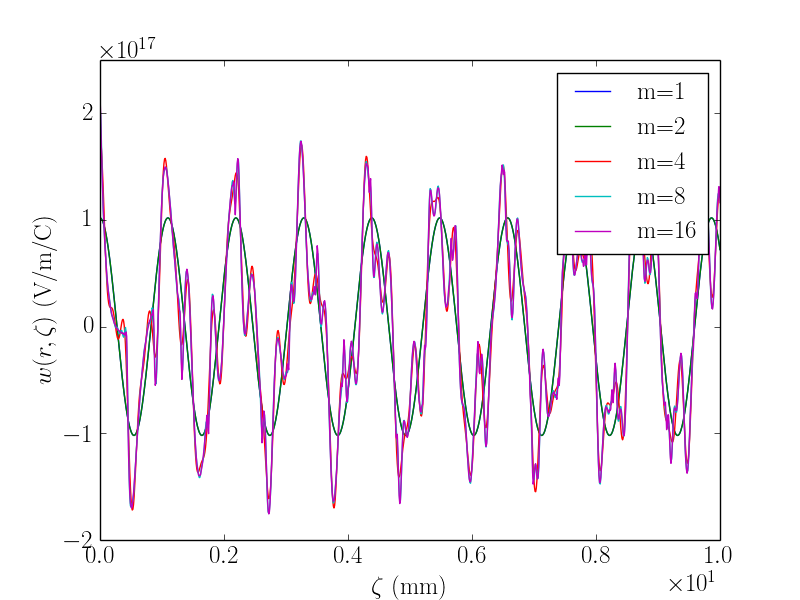
A feature critical to the production of density modulated beams is the capability to produce the required large local longitudinal-phase-space (LPS) chirps via the self-wakefield in the considered DLW structure. We investigate this point with a cylindrically-symmetric DLW consisting of a hollow dielectric cylinder with inner and outer radii and rg , and relative electric permittivity . The outer surface of the dielectric is metalized. We consider the axial longitudinal wakefunction modes supported by such a structure to be of the form chao ; stupakov
| (1) |
where is the position of the observer charge referenced with respect to the source electron and (with units of V/m/C) and are respectively the loss factor and wave vector associated to the mode supported by the DLW structure. The mode parameters and are obtained following the methodology described in Ref. rg by numerically solving the dispersion equation.
An example of computed Green’s function for a structure with parameter m, m, and (corresponding to diamond) appears in Fig. 1. The Green’s function converges after inclusion of 4 modes (the 50-m thickness of the structure supports multiple modes with significant axial fields).
Note that the field in Eq. 1 and the wake function have no dependence on the transverse coordinates. The expected change in longitudinal momentum for a particle within and behind a bunch with line-charge distribution is obtained from the convolution integral
| (2) |
where is the length of the DLW structure and the longitudinal coordinate within the bunch.
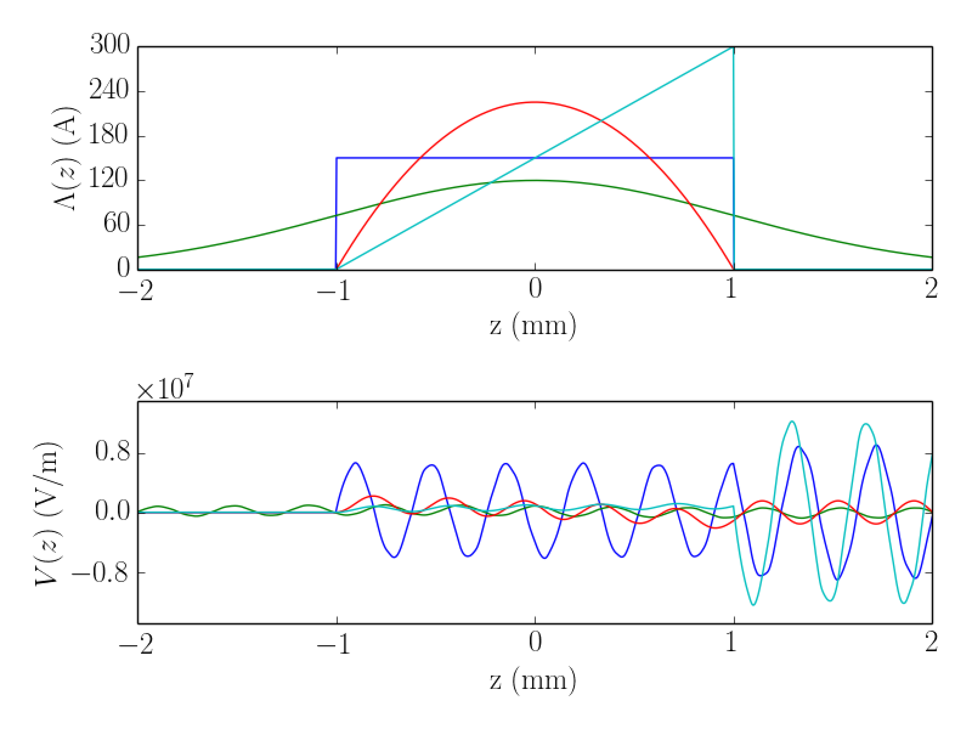
In contrast with an energy modulation imparted by external fields (e.g. from lasers or RF cavities), the modulation imparted via wakefield depends on the bunch shape. In particular, given the selected parameters for the DLW structure, one should ideally select an electron-bunch distribution with spectral contents capable of exciting the mode(s) supported by the structure; see Fig. 2. Reference antipov4 utilizes a relativistic bunch shape with linearly-ramped current profile as the associated energy modulation was shown to exhibit a uniform-amplitude modulation throughout the bunch.
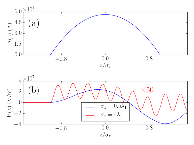
In order to illustrate the proposed concept we elaborate a simple model based on the ideal case of a line-charge electron bunch with a parabolic charge-density profile where is the total bunch charge and the half width of the distribution; see Fig. 3(a). The corresponding change in energy along the bunch is given by
where . Considering only the fundamental mode () and assuming a “cold” initial LPS with no correlation so that (for all ), where and are respectively is the axial coordinate and fractional momentum spread associated to the electron. The final fractional momentum spread downstream of the DLW structure becomes
| (4) |
where is the bunch’s initial mean energy, , and is the usual “sampling function”.
After a section with longitudinal dispersion , the energy modulation induces a density modulation and the final longitudinal coordinate of an electron is mapped as under a linear single-particle dynamics approximation.
We first consider the case when the root-mean-square (rms) bunch length satisfies so that an energy modulation along the bunch can be impressed; Fig. 3(b, red trace). In such a case the second term in Eq. II dominates the short-wavelength modulation structure and the final longitudinal coordinate is approximately given by
| (5) |
At the zero-crossing locations, i.e. the locations along the bunch such that , the local LPS correlation is given by
| (6) |
where we have further assumed that the in the denominator is negligible. The maximum bunching occurs at these zero-crossing points when the following beamline provides a longitudinal dispersion .
The characteristic length of the microbunches formed is approximately given by where is the
uncorrelated (or slice) rms fractional momentum spread. The microbunches’ separation is for an incoming beam with vanishing
correlated energy spread upstream of the DLW structure.
At relativistic energies, the longitudinal dispersion necessary to form the microbunches is often provided by a dispersive section, e.g., a bunch-compressor chicane carlstenBC as accomplished in Ref. antipov4 . Here we note that at energies below MeV (non-ultra-relativistic regime), the large LPS slope resulting from the large axial fields supported in a DLW requires a relatively small that can be readily produced by a drift space. A drift with length has a longitudinal dispersion
| (7) |
where is the bunch’s Lorentz factor and we take for simplicity.
Practically, for a -MeV electron bunch passing through a 10-cm long DWL structure capable of supporting MV/m peak field a “local” chirp m-1 can be obtained for a 0.5-mm modulation wavelength. The corresponding local density spike could form via ballistic bunching after a drift of length below m. The expected modulation amplitude MeV is much larger than the typical uncorrelated energy spread of a few keV routinely achieved in RF guns huang ; huening . Additionally, the relatively low and small uncorrelated energy spread are also beneficial to the production of very short (-fs) density spikes.
This simple estimate motivates further investigation of the scheme using a bunch generated by a conventional photoemission electron gun.
In addition, furthering our point about the dependence of the energy modulation on bunch parameters we now examine the case when the rms bunch length fulfills ; see Fig. 3(b, blue trace). In this regime, the induced energy change along the bunch produced an energy depression between the head and tail of the bunch. The produced correlation between the depleted energy location and tail has the proper sign to be compressed via ballistic bunching. Although the introduced chirp is nonlinear, it eventually can lead to the production of high-peak-current spikes. This approach however only bunches a fraction of the bunch and actually debunch the beam within the front of the bunch. Despite this drawback, this scheme is appealing given its simplicity and absence of need for a precisely synchronized external field as used in ballistic bunching using a buncher cavity luiten . This passive bunching method is therefore inherently self synchronized and in principle not subject to time jitter (the main source of jitter is associated to charge fluctuations that impact the imparted energy modulation and could consequently result in shot-to-shot fluctuation of the peak-current value).
Finally, it should be pointed out that higher-order, e.g., dipole, modes can also affect the bunch transverse dynamics but are neglected in the present treatment as we assume the bunch is cylindrical-symmetric and is centered on the DLW axis. Given the short length of the DLW considered in the remainder of the paper, possible detrimental effects on the transverse beam dynamics can be practically corrected, e.g., by mounting the DLW structure on translational stages.
III Numerical modeling and analysis
To explore the possibilities discussed in the previous section we perform beam-dynamics simulations. The numerical simulations are carried with the beam-dynamics program astra astra which takes into account space-charge effects using a cylindrical-symmetric quasi-static space charge algorithm. The beam-DLW interaction is modeled via the Green’s function approach briefly outlined above and detailed in Ref. dohlus . In the simulations the electron bunch is modeled as an ensemble of 100,000 macroparticles.
To characterize the temporal structure of the bunch, we represent the macroparticles’ temporal distribution as and compute the bunch factor factor (BFF) as
| (8) |
where is the number of macroparticles used in the simulation. The BFF is commonly used to characterize the performance of accelerator-based radiation source saxon . We note that in some cases, e.g. for the production of coherent radiation, transverse suppression effects might be prominent and should be properly accounted for by utilizing a three-dimensional expression for the BFF; see, e.g., Ref. saldin .
III.1 Sub-picosecond bunch train formation
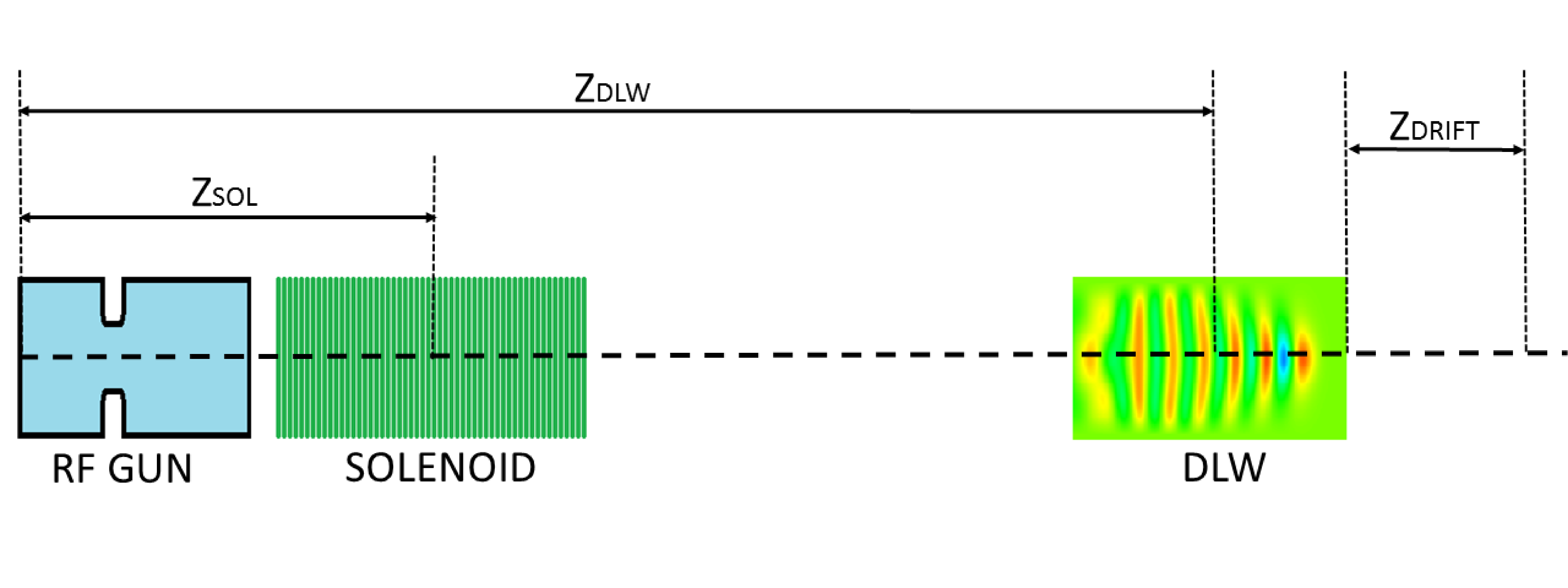
We first investigate the practical realization of the scheme described in section II to produce trains of sub-picosecond bunches and to demonstrate the versatility of the method, we consider two examples of implementation. The generic setup consists of an RF-gun electron source followed by a DLW as diagrammed in Fig. 4. Downstream of the DLW the beam is focussed with a second solenoid, e.g., to produce a waist at the location a transition-radiation target. The RF gun is taken to be an S-band (2.856 GHz) 1/2-cell cavity similar to the one currently in use at the linac coherent light source (LCLS) slacgun . Similar results are then confirmed using a 1/2-cell L-Band (1.3 GHz) gun similar to the one used at the FLASH facility in DESY pitz .
| S-Band | L-Band | ||
| parameter | units | ||
| Laser pulse RMS duration | 3 | 7 | ps |
| Laser pulse rise time | 100 | 100 | fs |
| Laser RMS spot size | 0.72 | 1.1 | mm |
| Initial charge | 1 | 1 | nC |
| Peak field on cathode | 120 | 34 | MV/m |
| Solenoid 1 position | 0.20 | 0.0 | m |
| Solenoid 1 strength | 0.26 | 0.17 | T |
| Solenoid 2 position | 1.35 | 1.0 | m |
| Solenoid 2 strength | 0.45 | 0.15 | T |
| DLW position | 0.9 | 0.34 | m |
| DLW inner radius | 350 | 500 | m |
| DLW outer radius | 363 | 550 | m |
| DLW length | 11 | 4 | cm |
| DLW fund. frequency | 1000 | 400 | GHz |
| Transmission through DLW | 85 | 98 | % |
| Average kinetic energy | 6.1 | 3.8 | MeV |
The photocathode-laser distribution was chosen to follow a plateau temporal distribution and its transverse size along with the location of the DLW, and solenoid strength were optimized using a multi-objective optimizer genOpt to maximize beam transmission through the structure and minimize the transverse beam size at the DLW center. The list of optimized operating parameters are displayed Tab. 1 (“S-band” column). We note that the choice of the DLW parameters is a compromise between modulation wavelength , energy modulation amplitude – which affects the bunching parameter – and beam transmission. For example, a shorter DLW structure relaxes the requirements on beam sizes and emittances at the structure, but necessitates a longer drift to bunch the beam (as the imparted energy amplitude modulation is smaller than for a longer structure). Additionally, the number of potential microbunches depends on the incoming bunch length and . For example, a Gaussian bunch with rms length will eventually result in the generation of microbunches; varying for a given bunch charge and affects the initial peak current and amplitude of the imparted energy modulation as inferred from Eq. 4.
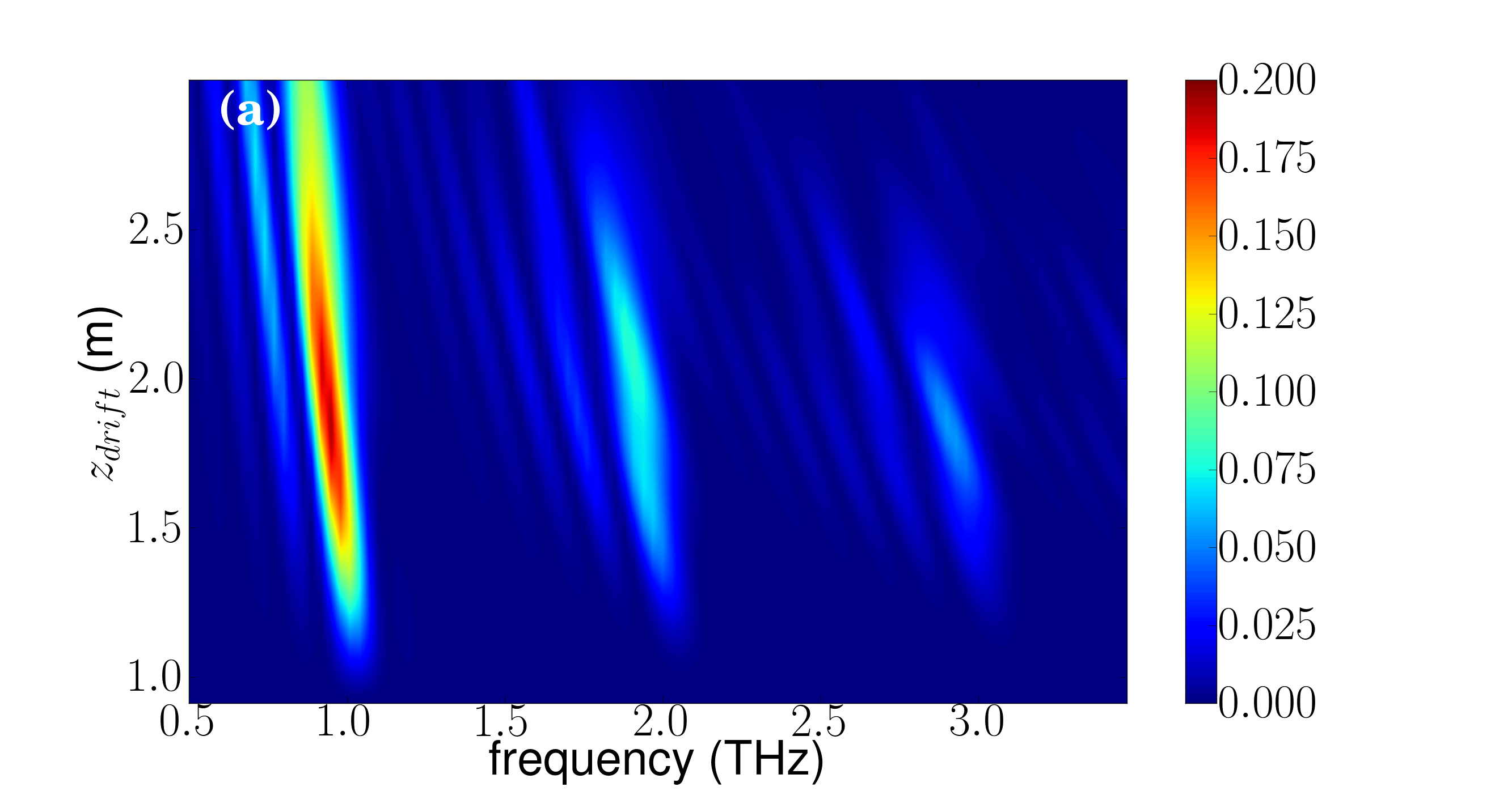
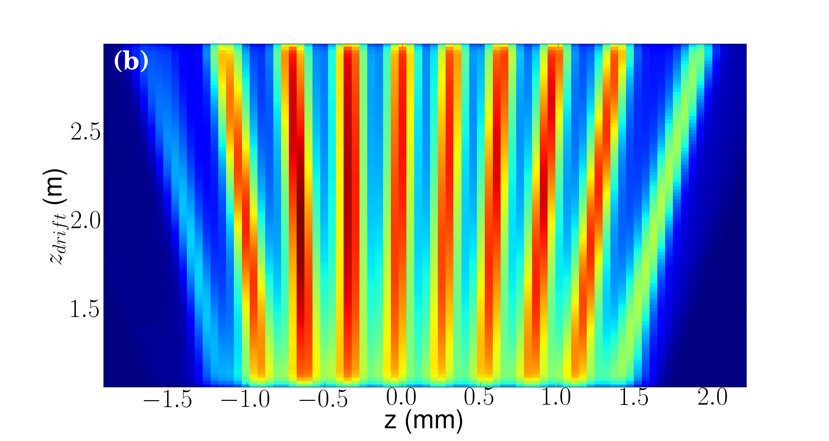
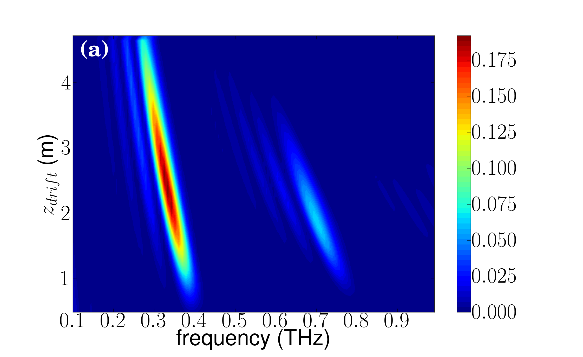
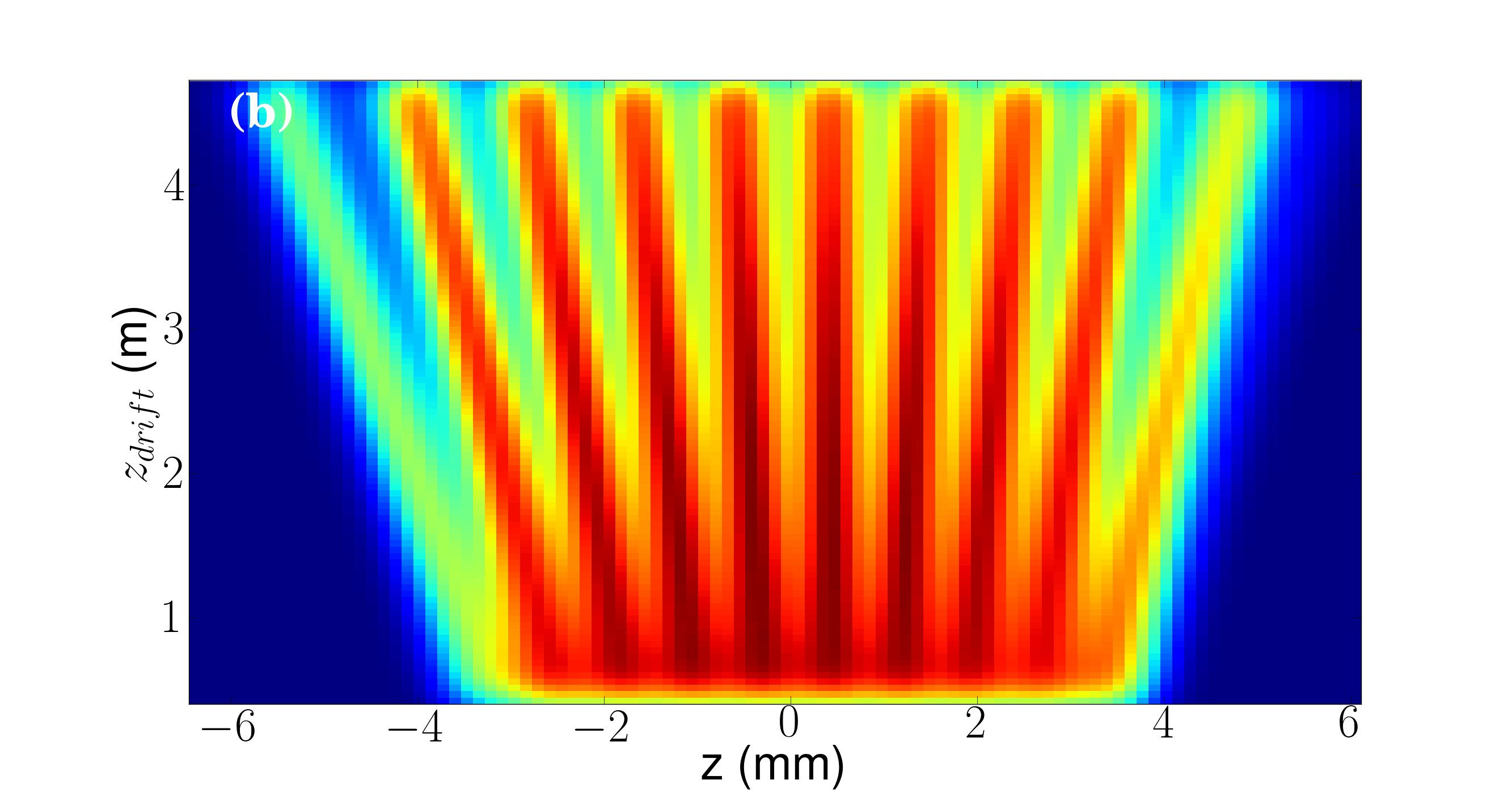
We present, for the “S-band” case of Tab. 1, the evolution of the BFF over a frequency range THz as a function of drift distance from the DLW exit () in Fig. 5(a). The corresponding longitudinal-density evolution appears in Fig. 5(b). For this set of parameters, 10 microbunches are produced and a maximum bunching of is obtained at the DLW fundamental mode’s wavelength m. In addition, harmonics of the fundamental mode are observed. For the selected DLW parameters and the corresponding thin dielectric layer, only the fundamental mode significantly influences the bunch dynamics.
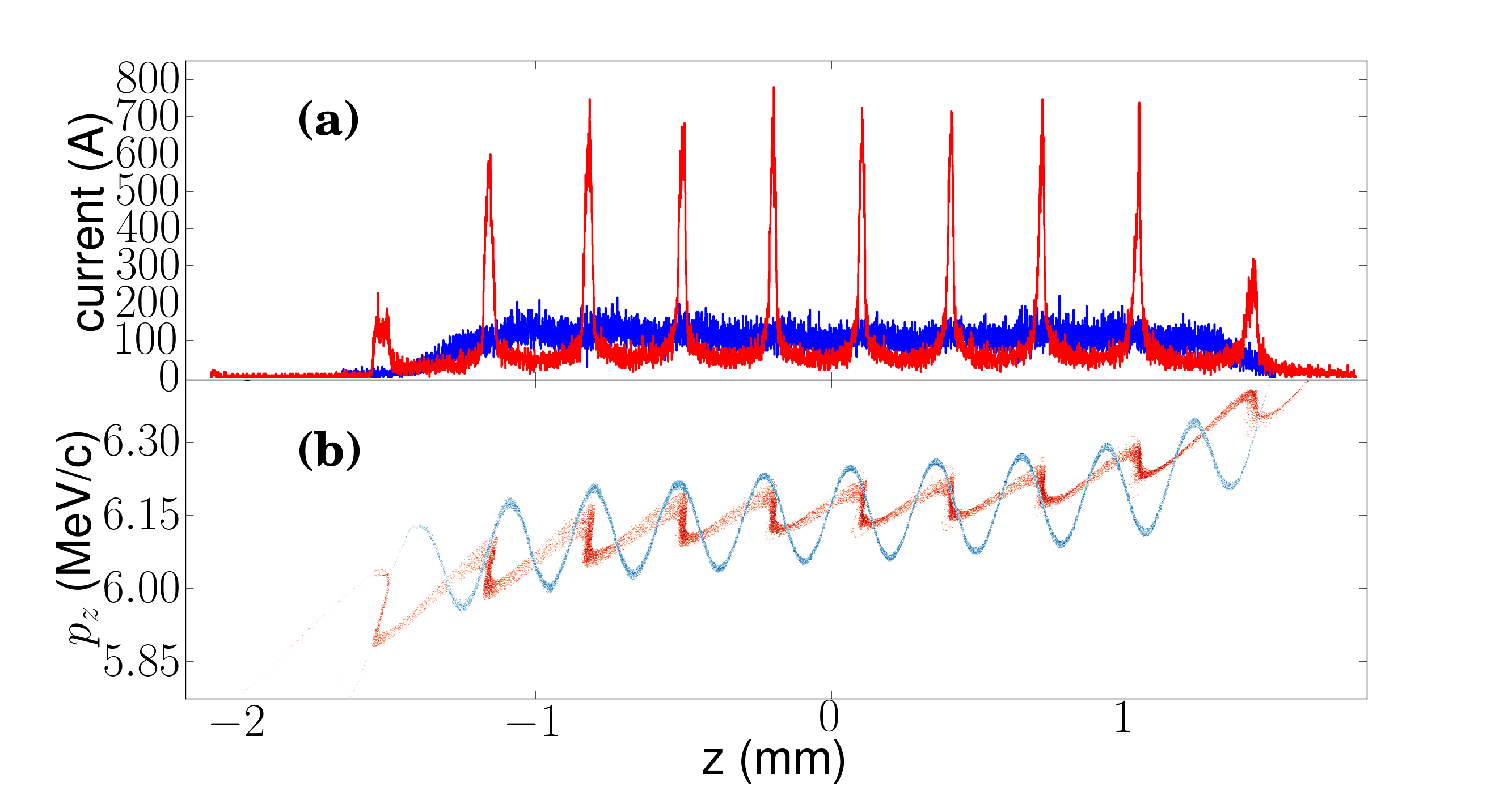
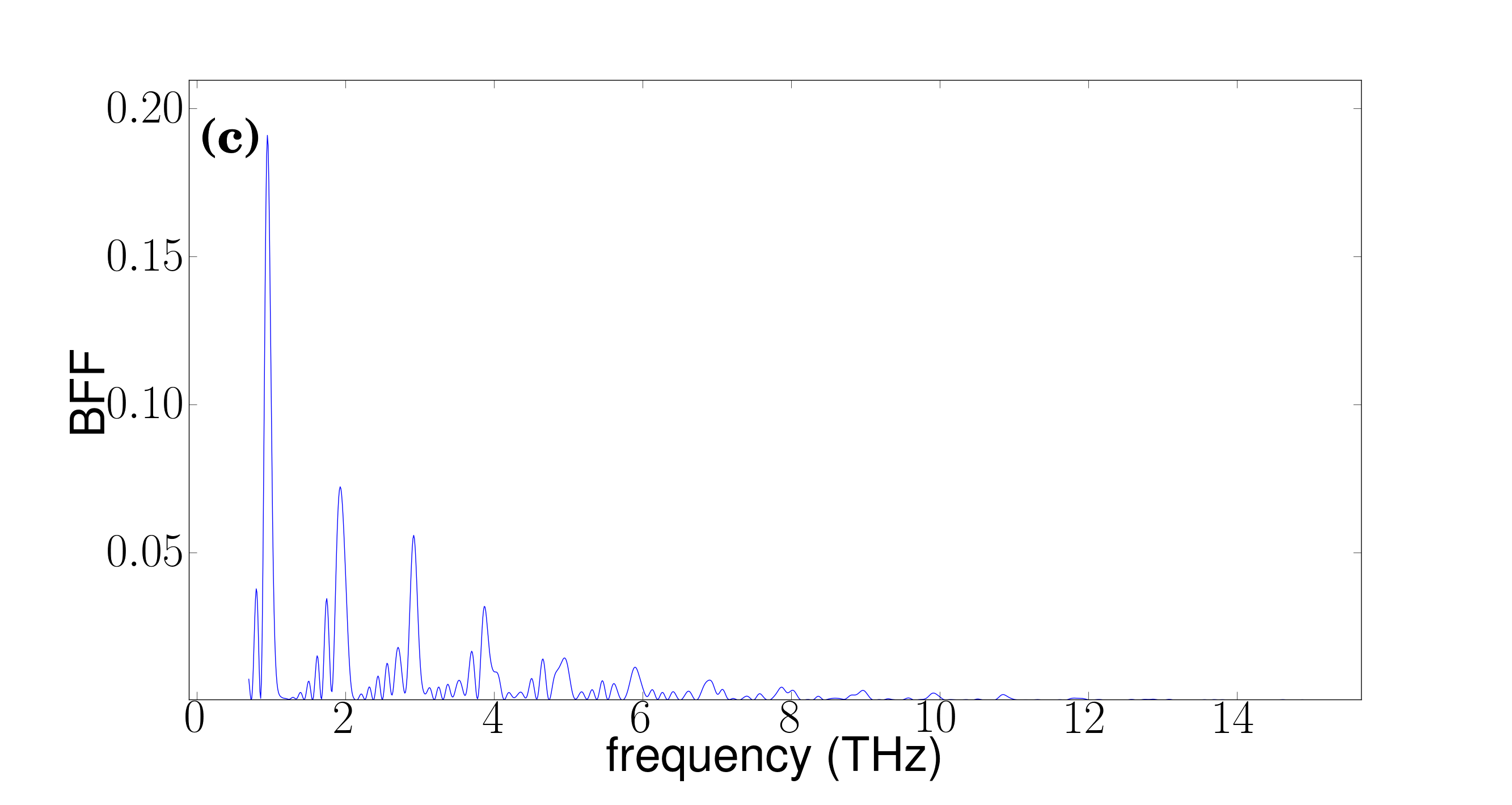
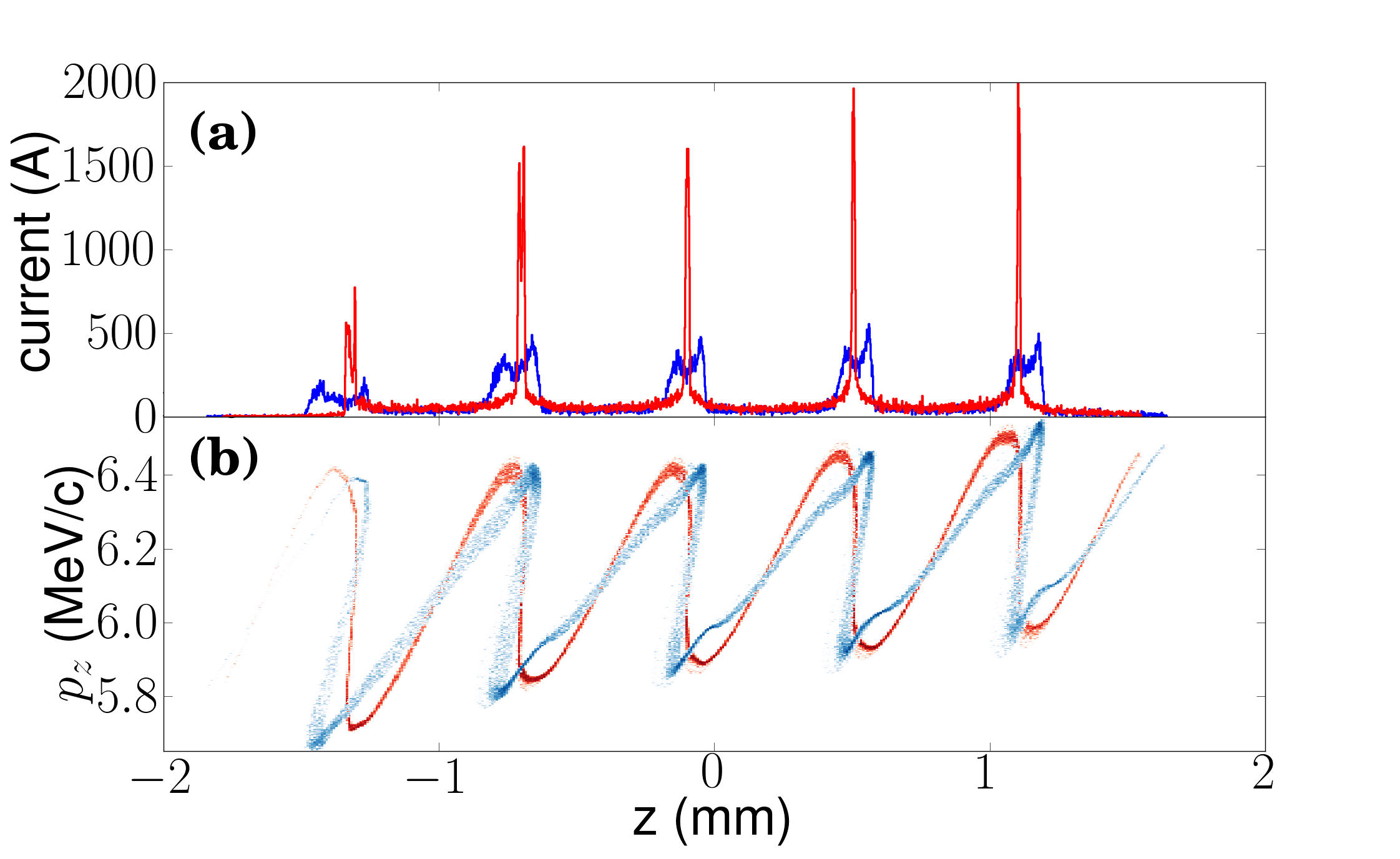
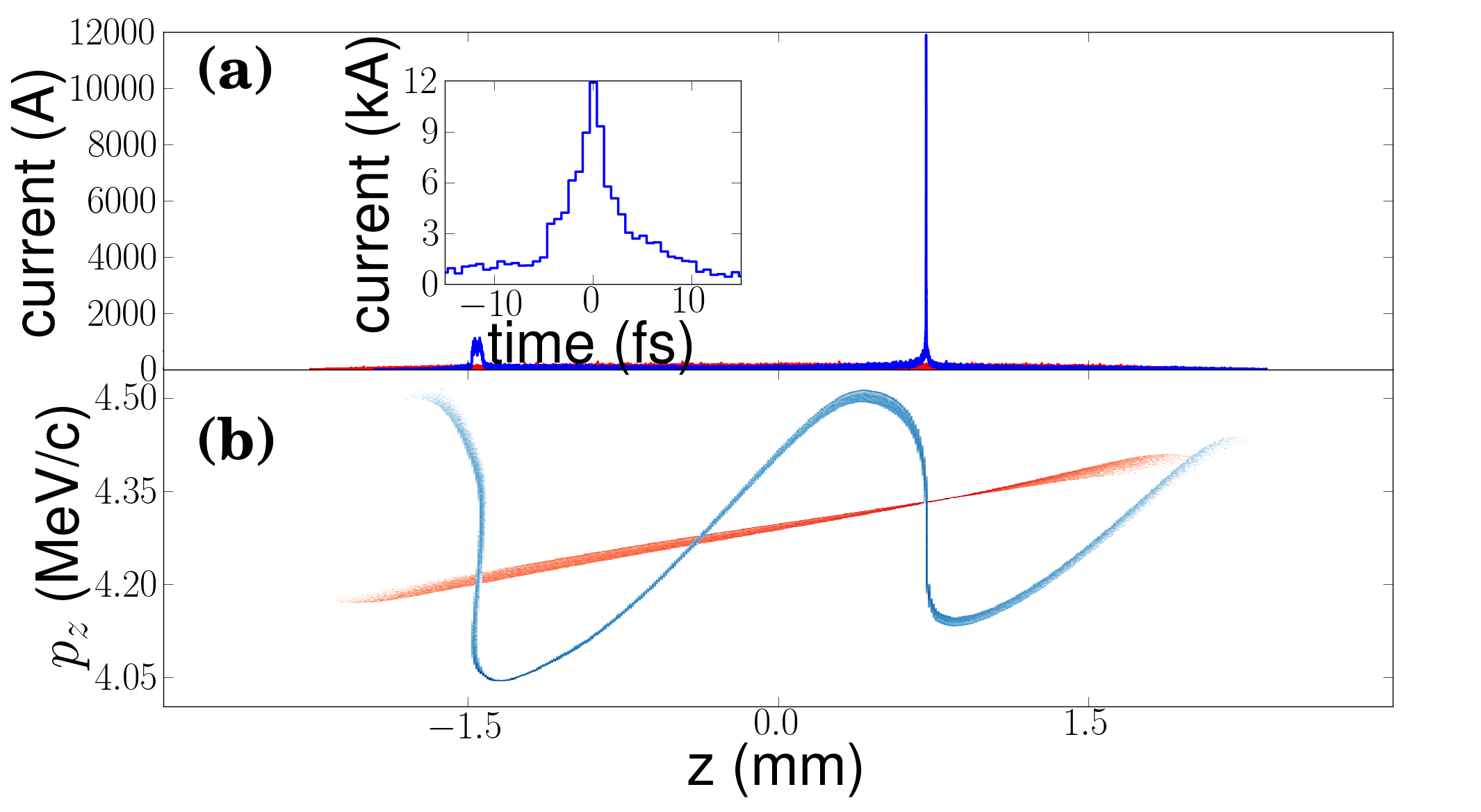
The current and LPS distributions at the DLW entrance and at the location of maximum bunching (at m from the photocathode) appear in Fig. 6. Peak current on the order of 1 kA are achieved for a beam with mean momentum of MeV/c. The shortest current spike generated has an full-width half-max (fwhm) duration of fs. These results are comparable to the one experimentally obtained through wave-breaking in Ref. renkai albeit with a much higher contrast ratio pietroLSC . The origin of the non-uniform bunching across the beam with peak-to-peak variation in the microbunch current is twofold. First, the slice-energy-spread positional variation along the bunch affects the shortest structure achievable at a given location. Second, the LPS prior to the DLW has initial correlations [as seen on the blue density plotted in Fig. 6(b)] which affect the bunching uniformity across the microbunches. This latter initial correlation is also responsible for the apparent “walk-off” feature (the microbunches spread apart from each others as they drift) of the microbunches visible in Fig. 5(b). Figure 6(c) indicates strong harmonic content at the second and third harmonic frequencies of is also observed at the location of maximum bunching.
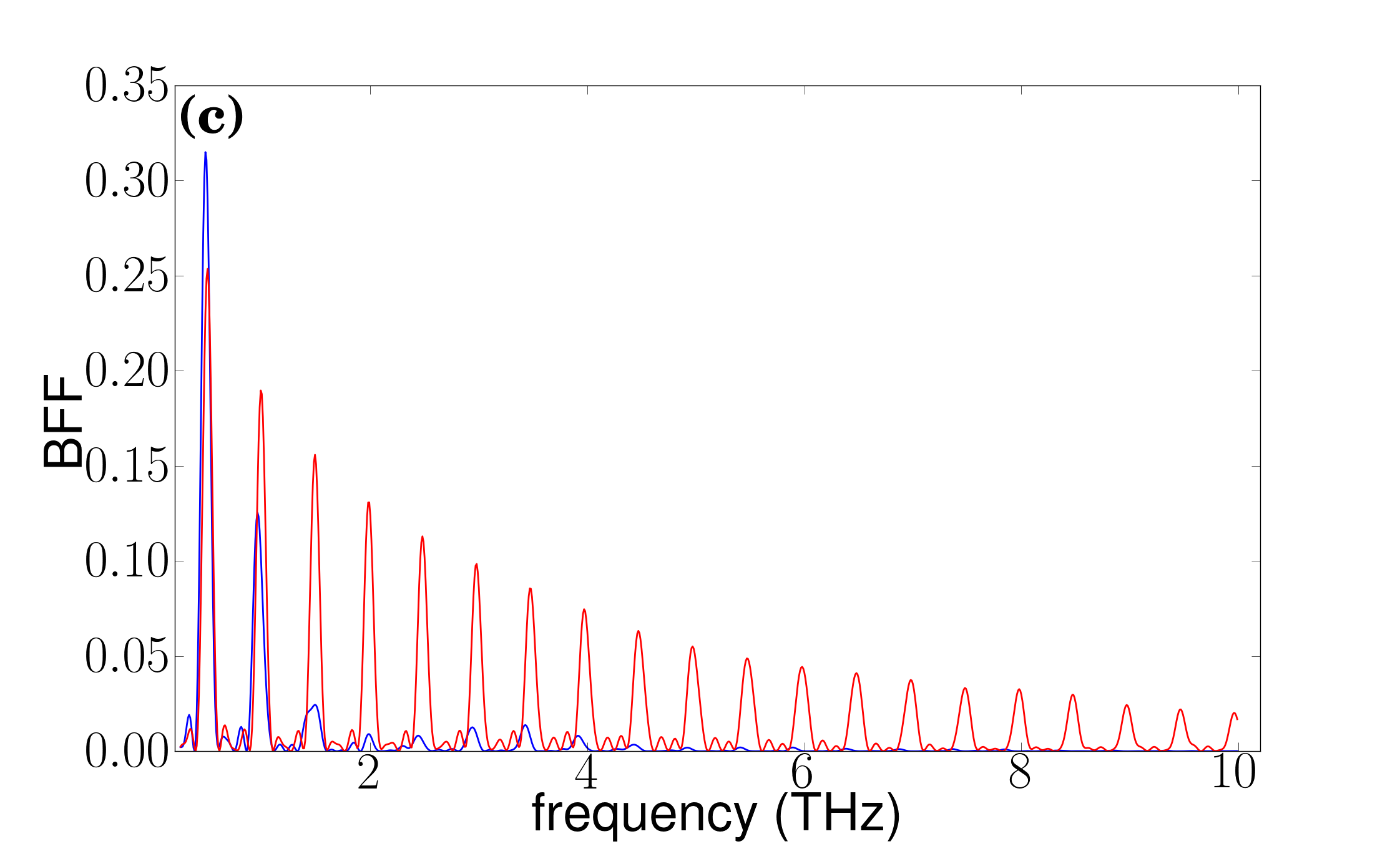
Moreover, the higher harmonics are limited by the precision of the micro-bunch spacing within the bunch; a higher frequency DLW will lead to more micro bunches which will be more limited by the initial correlated LPS. We can investigate this feature by using a lower frequency structure of 500 GHz in the same context of the 1 THz example illustrated above. The current and LPS is shown in Fig. 7(a,b) and associated BFF over the frequency range (0.25 THz, 10 THz), is shown in Fig. 7(c) for maximum compression (red trace). The very strong higher harmonic content is notably due to the precise spacing of the microbunches. Additionally, we may want to suppress higher harmonics or amplify the fundamental; this can easily be done by selecting a bunch which is under or over-compressed such that the micro-bunches span a larger spatial extent; see Fig. 7(a,b,c) blue trace.
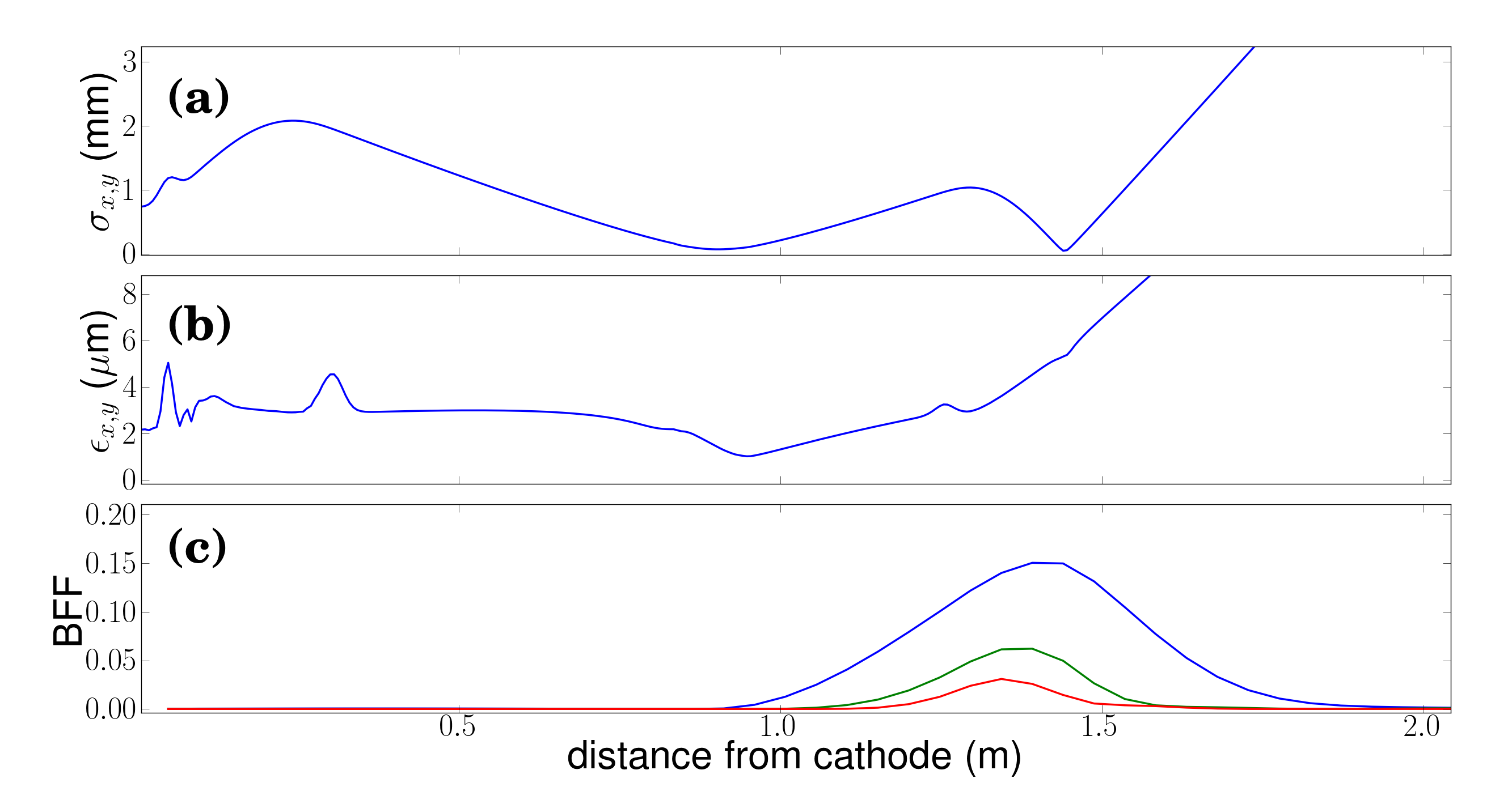
Finally, the evolution of the transverse beam sizes and emittance is respectively shown in Fig. 8(a) and (b) for the case presented in Fig. 6. The addition of a second solenoid at m can transversely focus the beam down to m at an axial location close to the maximum bunching; see Fig. 8(c). The simulated small rms beam size confirms that the one-dimensional BFF approach adopted earlier can accurately be used to estimate the properties of radiation emitted at wavelengths m. It is therefore applicable to the THz regime. The small transverse size could also permit the use of a second DLW as a narrowband THz radiator as explored in Ref. cook .
The location of maximum bunching depends primarily on the wakefield amplitude compared to the average bunch energy. Applying higher peak fields in the RF-gun leads to larger ballistic bunching lengths downstream of the DLW structure and vice versa. Alternatively, shorter bunching lengths can be achieved by decreasing the bunch length at the cost of more microbunches. To confirm the applicability of our concept to other configurations we carried a similar study as the one presented above for the case of an L-band RF gun.
For this case we consider the setup available at the Fermilab’s A0 photoinjector carneiro which incorporates a first-generation L-band gun used at the decommissioned Tesla-test facility at DESY TTF1 . The gun is nested in three solenoidal lenses. An optimization similar to the one carried for the S-band case was conducted and the resulting operating parameters are displayed in Tab. 1 (“L-band” column). For completeness the BFF and longitudinal density evolution downstream of the DLW are shown in Fig. 9. As in the S-band case we observe strong bunching at the DLW fundamental mode’s frequency (in this case m as the DLW parameters are different). But in contrast with the S-band case the higher-harmonic content of the BFF are significantly suppressed. The change in the fundamental frequency as the bunch drift downstream of the DLW appear stronger than for the S-band case and is due to a more prominent “walk-off” effect due to the lower beam energy.
III.2 Passive Bunching and Shaping
We now turn to another potential application of the scheme detailed in Section II to bunch or shape an electron beam produced via photoemission
from an RF gun (this corresponds to the case when ).
To illustrate our point, we consider the case of the L-band gun just discussed in the previous section and instead of using the DLW parameters of Tab. 1, we consider a structure with inner radius m to produce a global correlated energy spread as the fundamental-mode wavelength of the DLW becomes comparable to the bunch length. We use a 10-cm long DLW structure and note that due to the relatively large wavelengths required, the aperture becomes larger and the beam size requirement are significantly relaxed. As mentioned earlier, the inherent nonlinear LPS distortion exhibits a correlation between the depleted energy location and tail that has the proper sign for compression via ballistic bunching.
We exemplify this possibility by exploring the change in peak current downstream of a DLW structure with fixed inner radius m as a function of the fundamental-mode wavelength. The mode’s wavelength is varied with different dielectric thicknesses due to the relatively small impact on the bunching length compared to changing directly. The results appear in Fig. 10 and indicate that a peak current of kA are attained when the fundamental-mode wavelength is mm (corresponding to ).
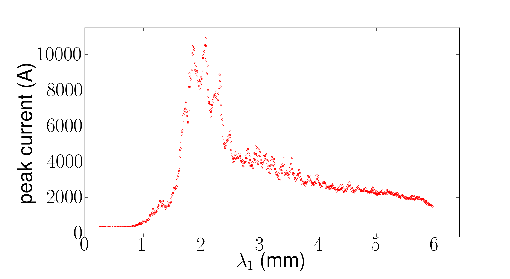
The latter wavelength
corresponds to a structure with outer radius m (or dielectric thickness m). The associated current profiles
and LPS appear in Fig. 11 and illustrates the role of the initial longitudinal emittance of the bunch before the DLW (i.e. the maximum
peak current is achieved for an initial axial slice with the smallest slice energy spread.) In Fig. 11 only 7.1% of the population resides
within the current spike while the rest contributes to the formation of longitudinal tails. This low-current population of the bunch could in principle be reduced via dispersive scraping or by
exploring some energy-transverse correlations in conjunction with transverse collimators. Also, due to the relatively large inner radii needed to support wavelengths comparable to the bunch length, this technique can in principle easily be scaled to higher bunch charges. Finally, we note that the current profiles shown in Fig. 11 can actually find applications,
e.g. to investigate wakefield effects in accelerating structures asset and in compact beam-driven acceleration schemes utilizing low-energy drive
bunches.
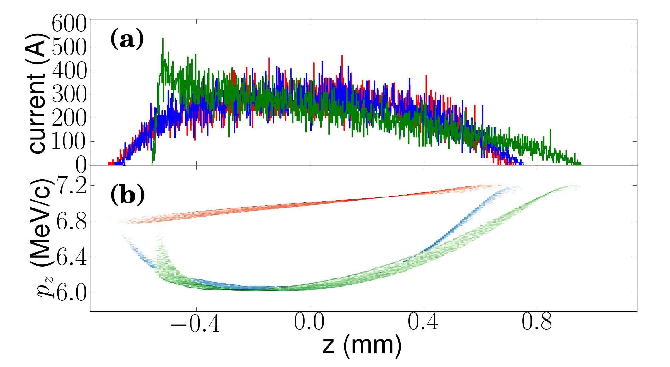
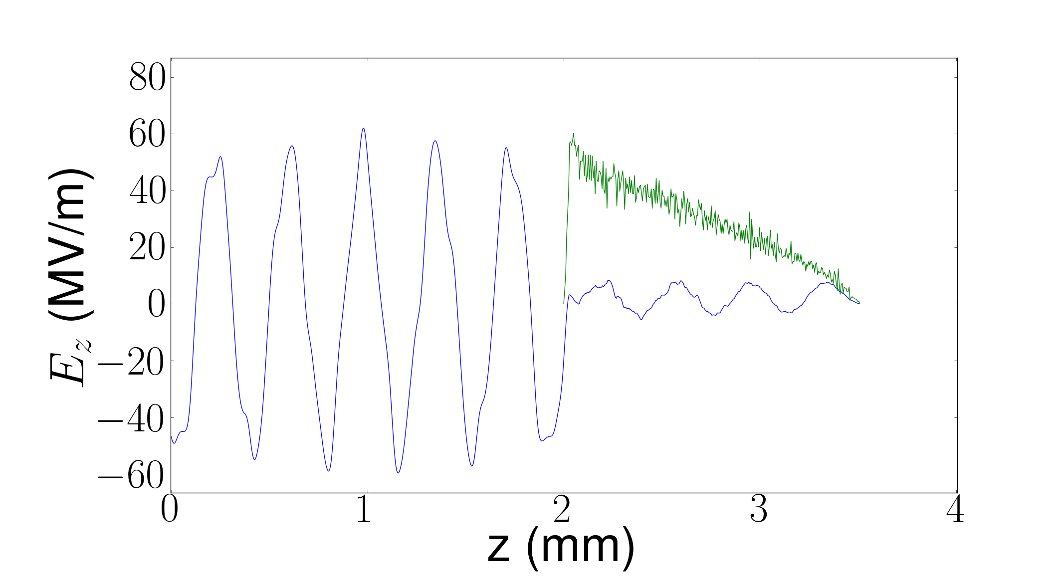
As a final application we investigate the possibility to produce low-energy bunches with linearly-ramped current profiles. This type of distribution is sought after to improve the transformer ratio – the maximum accelerating wakefield over the decelerating field experienced by the driving bunch – in collinear beam-driven acceleration schemes bane . We demonstrate that a standard distribution typically produced downstream of an RF gun can be transformed into a ramped bunch with quasi-linear dependency on . We take the example of the S-band gun considered in Sec. III.1 and set where is the full longitudinal size of the bunch upstream of the DLW structure. For these simulations, the axial-field amplitude at the cathode is set to MV/m. Such an increase (compared to the set of parameters displayed in Tab. 1) was required to mitigate bunch lengthening. Figure 12 depicts the LPS evolution and associated current profiles associate to the bunch as it enters (red trace), exits (blue trace) the DLW and after a drift of 0.2 m (green traces). The interplay of the DLW field and longitudinal-space charge force results in the appearance of nonlinear correlations in the LPS. These nonlinearities provide some control over the current profile.
To quantify the performance of the current profiles simulated in Fig. 12(b, green trace), we compute the expected wakefield that such a bunch would produce in a DLW structure optimized to sustain a large axial field. The structure’s inner and outer radii are respectively m, m and the relative dielectric permittivity is kept to . The resulting wakefield behind the bunch has a peak accelerating field amplitude of MV/m; see Fig. 13. The transformer ratio is numerically inferred as where MV/m is the maximum amplitude of the decelerating electric field within the electron bunch. The achieved transformer ratio of is comparable to the ideal ratio of predicted for an ideal linearly-ramped current profile (here is the number of mode wavelength comprised within the total bunch length) bane . Depending on the desired application, the photoinjector settings and DLW parameters could be adjusted to produce a ramped current profile after further acceleration in a subsequent linac.
Finally, a finer control over the bunch shape could possibly be implemented using several DLW structures with properly selected fundamental-mode wavelengths. Such a multifrequency DLW approach would be an extension of the scheme described in Ref. piotPRLshaping to higher frequencies.
IV SUMMARY
In summary, we presented a relatively simple technique to bunch non-ultrarelativistic beams commonly produced by photoinjectors. The method was shown to support the generation of bunch train consisting of sub-picosecond microbunches. Alternatively, we demonstrated that a DLW with a lower-frequency fundamental mode could act as a passive buncher and produce multi-kA bunches. In addition, we discuss the application of the technique to form bunches with linearly-ramped current profiles as needed to improve the transformer ratio in beam-driven advanced-acceleration techniques. One of the main advantages of the method is that it relies on the bunch interaction with its self-induced fields which are inherently synchronized: the technique is therefore not prone to temporal jitter.
We expect the proposed method to find useful applications that span accelerator-based compact THz-radiation sources, ultra-fast electron diffraction and in photoinjectors for short-wavelength linacs.
It is also worth noting that the scheme could in principle be combined with other electron-emission process (e.g. thermionic- or field-emission) but a detailed exploration is beyond the scope of the present study.
Finally, other wakefield mechanisms, e.g., the use of a corrugated pipe marcus2 ; corrugated could provide an alternative to DLW and lead to similar results PIERS . Our
selection of a DLW structure was mainly motivated by its manufacturing simplicity and wide use in advanced accelerator R&D.
This work was supported by the Defense Threat Reduction Agency, Basic Research Award # HDTRA1-10-1-0051, to Northern Illinois University and by the Department of Energy contracts No. DE-FG02-08ER41532 and No. DE-SC0011831 with Northern Illinois University. PP is partially supported by DOE contract DE-AC02-07CH11359 to the Fermi research alliance LLC.
References
- (1) A. H. Zewail and J. M. Thomas, 4D Electron Microscopy: Imaging in Space and Time, Imperial College Press, London, 2010.
- (2) R. K. Li, P. Musumeci, H. A. Bender, N.S. Wilcox, M. Wu, J. Appl. Phys. 110 (7), 074512 (2011).
- (3) A. Gover, Phys. Rev. ST Accel. Beams 8, 030701 (2005).
- (4) A.-S. Müller, Rev. Accl. Sci. Tech., 03, 165 (2010).
- (5) A. Modena, Z. Najmudin, A.E. Dangor, C.E. Clayton, K.A. Marsh, C. Joshi, V. Malka, C.B. Darrow, C. Danson, D. Neely, and F.N. Walsh, Nature (London) 377, 606 (1995).
- (6) D.F. Gordon, A. Ting, T. Jones, B. Ha zi, R.F. Hubbard, P. Sprangle, “Particle-in-cell simulation of optical injector for plasma accelerators”, in Proceedings of the 2003 Particle Accelerator Conference (PAC’03), 1846 (2003).
- (7) B. E. Carlsten and S. M. Russel, Phys. Rev. E 53, R2072-R2075 (1996).
- (8) X. J. Wang, , X. Qiu, and I. Ben-Zvi, Phys. Rev. E 54 R3121 (1996).
- (9) X. J. Wang, X. Y. Chang, Nucl. Instr. Meth. A 507 310 (2003).
- (10) P. Piot, L. Carr, W. S. Graves, and H. Loos, Phys. Rev. ST Accel. Beams 6, 033503 (2003).
- (11) M. Ferrario, et al. Phys. Rev. Lett. 104 054801 (2010).
- (12) T. van Oudheusden, P. L. E. M. Pasmans, S. B. van der Geer, M. J. de Loos, M. J. van der Wiel, and O. J. Luiten Phys. Rev. Lett. 105, 264801 (2010)
- (13) K. Flöttmann, Nucl. Instr. Meth. A 740, 34 (2014).
- (14) C. Sung, S. Ya. Tochitsky, S. Reiche, J. B. Rosenzweig, C. Pellegrini, and C. Joshi, Phys. Rev. ST Accel. Beams 9, 120703 (2006).
- (15) L. J. Wong, A. Fallahi, and F. X. Kärtner, Optics Express, 21 (8), 9792 (2013).
- (16) P. Muggli, V. Yakimenko, M. Babzien, E. Kallos, and K. P. Kusche, Phy. Rev. Lett. 101, 054801 (2008).
- (17) Y.-E Sun, P. Piot, A. Johnson, A. H. Lumpkin, T. J. Maxwell, J. Ruan, R. Thurman-Keup, Phys. Rev. Lett. 105, 234801 (2010).
- (18) P. Piot, Y.-E Sun, T. J. Maxwell, J. Ruan, A. H. Lumpkin, M. M. Rihaoui, and R. Thurman-Keup, Appl. Phys. Lett. 98, 261501 (2011)
- (19) Y.-C. Huang, Int. Jour. Mod. Phys. B 21, 287 (2007).
- (20) M. Bolosco, I. Boscolo, F. Castelli, S. Cialdi, M. Ferrario, V. Petrillo and C. Vaccarezza, Nucl. Instr. Meth. A 577, 409 (2007).
- (21) Y. Li and K.-J. Kim , Appl. Phys. Lett. 92, 014101 (2008).
- (22) P. Musumeci, R. K. Li, and A. Marinelli, Phys. Rev. Lett. 106, 184801 (2011).
- (23) S. Antipov, C. Jing, M. Fedurin, W. Gai, A. Kanareykin, K. Kusche, P. Schoessow, V. Yakimenko, and A. Zholents, Phys. Rev. Lett. 108, 144801 (2012).
- (24) D. R. Hamilton, J. K. Knipp and J. B. Horner Kuper, MIT Radiation Laboratory Series, Klystron and Microwave Triodes (McGraw-Hill, New York, 1948).
- (25) B. C. Yunn, “Physics of th JLAB 350-keV photoinjector”, in Proceedings of the 1999 Particle Accelerator Conference, PAC’99 (New York, 1999), 2453 (1999).
- (26) M. Rosing, and W. Gai, Phys. Rev. D 42, 1829 (1990).
- (27) A. Chao, Physics of Collective Instabilities in High-Energy Accelerators, Wiley Series in Beams & Accelerator Technologies, John Wiley and Sons (1993).
- (28) G. V. Stupakov, Wake and Impedance, report SLAC-PUB-8683, unpublished report available from the Stanford Linear Accelerator Center (2000).
- (29) P. B. Wilson, Introduction to wake fields and wake potentials, reports SLAC-PUB-4547 and SLAC/AP-66, unpublished reports available from the Stanford Linear Accelerator Center (1989).
- (30) S. Antipov, C. Jing, P. Schoessow, A. Kanareykin, B. Jiang, V. Yakimenko, A. Zholents, and W. Gai, AIP Conf. Proc. 1507, 421 (2012).
- (31) S. Antipov, M. Babzien, C. Jing, M. Fedurin, W. Gai, A. Kanareykin, K. Kusche, V. Yakimenko, and A. Zholents, Phys. Rev. Lett. 111, 134802 (2013)
- (32) S. Antipov, C. Jing, P. Schoessow, A. Kanareykin, B. Jiang, V. Yakimenko, A. Zholents, and W. Gai, Rev. Sci. Instrum. 84, 022706 (2013)
- (33) Z. Huang, D. Dowell, P. Emma, C. Limborg-Duprey, “Uncorrelated Energy Spread and Longitudinal Emittance of A Photoinjector Beam”, in Proceedings of the Particle Accelerator Conference, 2005. PAC 2005, 3570 (2005)
- (34) M. Hüning and H. Schlarb, Measurements of the beam energy spread in the TTF photoinjector , in Proceedings of the 2003 Particle Accelerator Conference (PAC03), 2074 (2003).
- (35) K. Flöttmann, astra: A space charge algorithm, User’s Manual, available from the world wide web at http://www.desy.de/mpyflo/AstraDokumentation (unpublished).
- (36) M. Dohlus, K. Flöttmann, and C. Henning, “Fast Particle Tracking With Wake Fields”, preprint arXiv:1201.5270 [physics.acc-ph] (2012); also report DESY 12-02 (available from DESY Hamburg, Germany).
- (37) J. S. Nodvick and D. S. Saxon, Phys. Rev. 96, 180 (1954).
- (38) E. Saldin, E. Schneidmiller, and M. Yurkov, Nucl. Instrum. Methods Phys. Res., Sect. A 539, 499 (2005).
- (39) D. T. Palmer, R. H. Miller, H. Winick, X.J. Wang, K. Batchelor, M. Woodle, and I. Ben-Zvi, “Microwave measurements of the BNL/SLAC/UCLA 1.6-cell photocathode RF gun”, in Proceedings of the 1995 Particle Accelerator Conference, PAC’95 (Dallas, TX, 1995), 982 (1996).
- (40) B. Dwersteg, et al., Nucl. Instr. Meth. A 393, 93 (1997).
- (41) M. Borland and H. Shang, geneticOptizer, private communication (2009).
- (42) P. Musumeci, R. K. Li, K. G. Roberts, and E. Chiadroni, Phys. Rev. ST Accel. Beams 16, 100701 (2013).
- (43) A. M. Cook, R. Tikhoplav, S. Y. Tochitsky, G. Travish, O. B. Williams, and J. B. Rosenzweig, Phys. Rev. Lett. 103, 095003 (2009).
- (44) J.-P. Carneiro, N. Barov, H. Edwards, M. Fitch, W. Hartung, K. Floettmann, S. Schreiber, and M. Ferrario, Phys. Rev. ST Accel. Beams 8, 040101 (2005).
- (45) J. Andruszkow, et al. [TESLA Collaboration], Phys Rev Lett 85, 3825 (2000).
- (46) C. Adolphsen et al. Next Linear Collider (NLC) Newsletter, 1, No. 2, August 2000 unpublished report available from the Stanford Linear Accelerator Center (2000).
- (47) K. L. F. Bane, P. Chen, P. B. Wilson, “On collinear wakefield acceleration”, SLAC-PUB-3662 (1985).
- (48) P. Piot, C. Behrens, C. Gerth, M. Dohlus, F. Lemery, D. Mihalcea, P. Stoltz, M. Vogt, Phys. Rev. Lett. 108, 034801 (2012).
- (49) M. Hüning, H. Schlarb, P. Schmüser, and M. Timm, Phys. Rev. Lett. 88, 074802 (2002).
- (50) P. Emma, M. Venturini, K. L. F. Bane, G. Stupakov, H.-S. Kang, M. S. Chae, J. Hong, C.-K. Min, H. Yang, T. Ha, W. W. Lee, C. D. Park, S. J. Park, and I. S. Ko, Phys. Rev. Lett. 112, 034801 (2014).
- (51) G. Mishra and G. Sharma, Progress In Electromagnetics Research M 36, 47 (2014).