Nonlinear motion and mechanical mixing in as-grown GaAs nanowires
Abstract
We report nonlinear behavior in the motion of driven nanowire cantilevers. The nonlinearity can be described by the Duffing equation and is used to demonstrate mechanical mixing of two distinct excitation frequencies. Furthermore, we demonstrate that the nonlinearity can be used to amplify a signal at a frequency close to the mechanical resonance of the nanowire oscillator. Up to 26 dB of amplitude gain are demonstrated in this way.
Due to their favorable geometry and potentially defect-free growth, nanowire cantilevers are promising as ultrasensitive force transducers for scanning probe microscopy Nichol08 ; Nichol13 ; Feng07 ; Poggio13 . Additionally, their relatively high mechanical resonance frequencies decouple their motion to a large degree from external noise sources, and should permit improved sensitivity in mass-sensing and scanning probe applications. Furthermore, the wide choice of nanowire growth material and the possibility to grow nanowire heterostructures could allow access to different measurement modalities, such as sensing of local electric or magnetic fields. In recent experiments Yeo14 ; Montinaro14 , coupling of optical transitions of a self-assembled quantum dot embedded in a nanowire to the motion of the nanowire through strain was demonstrated, opening the way to investigation of hybrid devices with nanowires as their main building blocks. Nanowire heterostructures are attractive as hybrid systems, as they can combine multiple functionalities in one integrated structure.
Conventionally, in scanning probe experiments oscillatory motion of the cantilever is driven with amplitudes small enough to remain in the linear dynamical regime. Due to a number of reasons Villanueva13 ; Lifshitz08 , including the oscillator geometry, nonlinear damping Eichler11 ; Zaitsev12 , the presence of external potentials, and nonlinear boundary conditions Moon83 ; Tabaddor00 , this linear dynamic range is often quite limited in nanoscale oscillators Antonio12 ; Postma05 ; Husain03 . The nonlinear dynamics occurring when this range is exceeded complicate the analysis of sensing experiments and are therefore generally avoided or compensated for Nichol09 . However, nonlinearities in general can also give rise to a host of useful effects, such as signal amplification Almog06 ; Karabalin11 , noise squeezing Almog07 , and frequency mixing Erbe00 . The nonlinear dynamics of nanowire cantilevers can enable these effects at the nanoscale in mechanical form and have the potential to enhance the performance of cantilever-based sensors.
In this Letter, we study the motion of several GaAs nanowires attached to their GaAs growth substrate (Fig. 1(a)). We observe that, upon driving the periodic bending motion of a nanowire with sufficiently large amplitudes, it can no longer be described by a linear equation of motion. Instead, the nanowire follows the, qualitatively different, nonlinear dynamics of a Duffing oscillator Nayfeh79 . A Duffing nonlinearity can give rise to complex motion of an oscillator, such as hysteresis, cascades of period-doubling, and chaotic motion Barger95 . In the quantum regime, Duffing nonlinearities have recently been studied in the context of mechanical squeezing Lue14 . Furthermore, we find that when applying two driving frequencies, the nanowire motion in the nonlinear regime contains components at frequencies other than the two driving frequencies, as a result of mechanical mixing.
The nanowires under investigation here are still attached to their GaAs growth substrate and are therefore singly clamped (see Fig. 1(a)). They have their fundamental mechanical resonances at frequencies of MHz (some nanowires show two closely spaced resonances, which we attribute to two transverse flexural modes that are non-degenerate due to a slight asymmetry of the nanowire cross-section) and exhibit quality factors of up to (at a temperature of 4.2 K and pressure below mbar), as determined from ringdown measurements. The nanowires were grown on a 4 nm SiO coated (111)B GaAs substrate by the catalyst-free Gallium-assisted method Colombo08 in a DCA P600 solid source molecular beam epitaxy system. Growth has been done under a rotation of 7 rpm, with a growth rate of 0.5s and a substrate temperature of 630∘C. The nanowires mostly exhibit zinc-blende crystal structure, hence hexagonal cross-sections, with typical diameters of 100 nm and lengths up to 25 m.
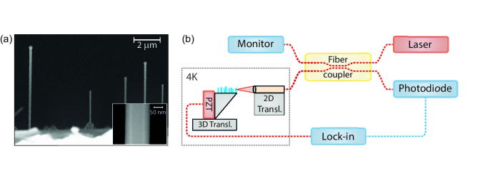
A schematic overview of the measurement setup is shown in Figure 1(b). The displacement of a nanowire is measured via a fiber-based interferometric method Hoegele08 . In this setup, the nanowire forms one reflecting interface of a low-finesse Fabry-Pérot interferometer, while the cleaved surface of a single-mode fiber forms the other interface. The sample is mounted on a stack of positioning stages for three-axis translation control, allowing the nanowire of choice to be positioned in the focal plane of an objective placed in front of the single-mode fiber. A voltage-controlled piezoelectric transducer (PZT) attached to the sample holder is used to drive oscillatory bending motion of the nanowires along the optical axis of the interferometer. A fiber coupler is used to inject light from a laser with a wavelength of 1550 nm into the interferometer. This wavelength is chosen in order to avoid spurious heating of the GaAs nanowires through absorption. The coupler diverts of the laser power towards the nanowire, resulting in a maximum power incident on the nanowire of 5W. The light reflected by the interferometer is collected by a photodiode with a dynamic range of 5 MHz. The oscillator of a lock-in amplifier actuates the PZT and the same lock-in amplifier demodulates the response of the photodiode. Sample and microscope are placed inside a vacuum can, which in turn is mounted inside a liquid helium bath cryostat.
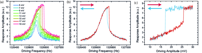
Figure 2(a) shows the measured displacement of a nanowire for various driving amplitudes. As the driving amplitude is increased, the resonance becomes broader and assumes a characteristic shark-fin shape when entering the nonlinear regime, where the frequency associated with maximum displacement increases and moves away from the resonator eigenfrequency . Such behavior is typical for a Duffing oscillator and can be described by the Duffing equation of motion:
| (1) |
Here is the displacement, the damping constant and the time-dependent driving force, here taken to be sinusoidal. The coefficient parametrizes the strength of the cubic nonlinearity. When is positive, as it is in our case, the nonlinearity increases the effective spring constant with increasing driving amplitude, thus stiffening the motion. The observed lineshape at higher driving amplitudes is a consequence of Eq. 1 having two stable solutions within a certain frequency range. This bistability leads to the switching phenomena seen at the right flank of the response peak (Fig. 2(a)). Which of the two solutions is realized, is determined by the initial conditions, and mechanical hysteresis can be observed when adiabatically sweeping the driving frequency or driving amplitude up and down (Figures 2(b) and (c)). The strength of the nonlinearity can be estimated from the shift of the frequency at which the maximum response amplitude occurs, using the relation Nayfeh79 : .
Our interferometer becomes nonlinear for larger driving amplitudes (see Fig. 2(a)), since then the displacement becomes comparable to the width of the interferometer fringes. We use this to infer Dobosz98 a value for the displacement of 250 nm, for a driving amplitude of 19 mV (Fig. 2(a)). We can then estimate to be of order m-2s-2 for this nanowire.
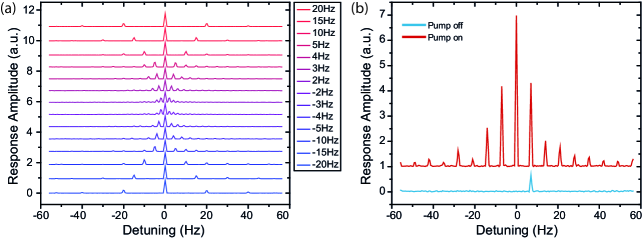
Next, we show that the nonlinearity can be used to turn a nanowire into a mechanical mixer Erbe00 ; Almog07 . Upon excitation with two driving frequencies, , the response shows sidebands additional to the motion at the driving frequencies, as shown in Figure 3(a). We observe up to twelve such sidebands, spaced around the driving frequencies with splittings equal to the detuning between the two driving frequencies, . Note that these measurements were taken with a different nanowire than before, and that higher driving amplitudes were required to enter the nonlinear regime.
This response can be understood from Eq. 1 by taking the cubic term to be a perturbation to the driving force and solving the equation iteratively Nayfeh79 ; Hutter10 . One then obtains new terms in the response at the intermodulation frequencies and (where is an integer) for each iteration. The amplitudes of these new intermodulation terms have coefficients proportional to , with and positive integers and . Hence, intermodulation terms are smaller for driving frequencies that are more detuned from resonance. Since the mixing occurs due to the cubic term in Eq. 1, for the intermodulation terms to be present, at least one of the driving amplitudes needs to be large enough to have an appreciable nonlinear response.
It is evident from Fig. 3 that the energy that is injected into the nanowire oscillator by the driving is distributed among the various intermodulation terms. This redistribution also occurs when one drive (signal) is much smaller than the other (pump), in which case amplification of the signal can take place Almog06 . The signal here is formed by a driving voltage supplied to the PZT, but it could be any force driving the nanowire with a frequency close to the resonance. Fig. 3(b) shows the spectral response of the nanowire motion with the signal drive always on, but with the pump excitation off in one case and on in the other. It is clear that amplification of the signal takes place when the pump excitation is switched on in the form of an increase in amplitude of the response at the signal frequency. Additionally, the appearance of the intermodulation terms, which is conditional on the presence of a signal, provides extra amplification. The total gain can be defined to be the ratio between the summed response amplitudes of all peaks present with pump drive, excluding the peak at the pump frequency itself, and the response amplitude with no pump drive. We observe a maximum gain of 26 dB.
In summary, we have observed and characterized nonlinear motion of as-grown GaAs nanowires. The nonlinearity is already observable for modest driving amplitudes. Furthermore, we have demonstrated that this nonlinearity allows for mechanical mixing of two excitations and amplification of a signal excitation through this mixing. This amplification could be utilized in several scanning probe techniques. For example, in the case where these nanowires act as mechanical force transducers, the observed gain of 26 dB could make force sensitivities of 100 zN/ in a narrow bandwidth feasible. These results indicate that although nonlinear motion can be non-negligible for nanowires, the nonlinearity can also be turned into an advantage using simple measurement schemes. The nonlinearity could in addition lead to coupling of different flexural modes. Such nonlinear mode coupling could have several applications, including tuning the resonance frequency Karabalin09 and quality factor Venstra11 of one mode through driving of the other mode, and implementing quantum non-demolition measurements of mechanical excitation Santamore04 .
Acknowledgements.
We thank Pengfei Wang, Jiangfeng Du, and Sascha Martin for technical support. This work is supported by an ERC Grant (NWscan, Grant No. 334767), the Swiss Nanoscience Institute (Project P1207), QSIT, and the Sino Swiss Science and Technology Cooperation (Project IZLCZ2 1388904).References
- (1) M. Poggio, Nature Nanotech. 8, 482-483 (2013).
- (2) J. M. Nichol, E. R. Hemesath, L. J. Lauhon, and R. Budakian, Appl. Phys. Lett. 93, 193110 (2008).
- (3) J. M. Nichol, T. R. Naibert, E. R. Hemesath, L. J. Lauhon, and Raffi Budakian, Phys. Rev. X 3, 031016 (2013)
- (4) X. L. Feng, Rongrui He, Peidong Yang, and M. L. Roukes, Nano Lett. 7, 1953-1959 (2007).
- (5) I. Yeo, P-L. de Assis, A. Gloppe, E. Dupont-Ferrier, P. Verlot, N. S. Malik, E. Dupuy, J. Claudon, J-M. Gérard, A. Auffèves, G. Nogues, S. Seidelin, J-Ph. Poizat, O. Arcizet, and M. Richard, Nature Nanotech. 9, 106-110 (2014).
- (6) M. Montinaro, G. Wüst, M. Munsch, Y. Fontana, E. Russo-Averchi, M. Heiss, A. Fontcuberta i Morral, R. J. Warburton, and M. Poggio, Submitted manuscript, (2014).
- (7) L. G. Villanueva, R. B. Karabalin, M. H. Matheny, D. Chi, J. E. Sader, and M. L. Roukes, Phys. Rev. B 87, 024304 (2013).
- (8) R. Lifshitz and M. C. Cross, Nonlinear Dynamics of Nanomechanical and Micromechanical Resonators, Reviews of Nonlinear Dynamics and Complexity Vol. 1, 1-52 (Wiley-VCH, Weinheim, 2008).
- (9) A. Eichler, J. Moser, J. Chaste, M. Zdrojek, I. Wilson-Rae, and A. Bachtold, Nature Nanotech. 6, 339-342 (2011).
- (10) S. Zaitsev, O. Shtempluck, E. Buks, and O. Gottlieb, Nonlinear Dyn. 67, 859-883 (2012).
- (11) F. C. Moon and S. W. Shaw, Int. J. Non-Linear Mech. 18, 465 (1983).
- (12) M. Tabaddor, Int. J. Solids Struct. 37, 4915 (2000).
- (13) D. Antonio, D. H. Zanette, and D. López, Nat. Commun., 806 (2012).
- (14) H. W. Ch. Postma, I. Kozinsky, A. Husain, and M. L. Roukesa, Appl. Phys. Lett. 86, 223105 (2005).
- (15) A. Husain, J. Hone, Henk W. Ch. Postma, X. M. H. Huang, T. Drake, M. Barbic, A. Scherer, and M. L. Roukes, Appl. Phys. Lett. 83, 1240 (2003).
- (16) J. M. Nichol, E. R. Hemesath, L. J. Lauhon, and R. Budakian, Appl. Phys. Lett. 95, 123116 (2009).
- (17) R. Almog, S. Zaitsev, O. Shtempluck, and E. Buks, Appl. Phys. Lett. 88, 213509 (2006).
- (18) R. B. Karabalin, R. Lifshitz, M. C. Cross, M. H. Matheny, S. C. Masmanidis, and M. L. Roukes, Phys. Rev. Lett. 106, 094102 (2011).
- (19) R. Almog, S. Zaitsev, O. Shtempluck, and E. Buks, Phys. Rev. Lett. 98, 078103 (2007).
- (20) A. Erbe, H. Krömmer, A. Kraus, R. H. Blick, G. Corso, and K. Richter, Appl. Phys. Lett. 77, 3102 (2000).
- (21) A. H. Nayfeh and D. T. Mook, Nonlinear Oscillations (Wiley, New York, 1979).
- (22) V. Barger and M. Olsson, Classical Mechanics: A Modern Perspective, second edition (McGraw-Hill, Inc., New York, 1995).
- (23) X. Y. Lü, J. Q. Liao, L. Tian, and Franco Nori, arXiv:1403.0049, (2014).
- (24) C. Colombo, D. Spirkoska, M. Frimmer, G. Abstreiter, and A. Fontcuberta i Morral, Phys. Rev. B 77, 155326 (2008).
- (25) A. Högele, S. Seidl, M. Kroner, K. Karrai, C. Schulhauser, O. Sqalli, J. Scrimgeour, and R. J. Warburton, Rev. Sci. Instrum. 79, 023709 (2008).
- (26) M. Dobosz, T. Usuda, and T. Kurosawa, Meas. Sci. Technol. 9, 232 (1998).
- (27) C. Hutter, D. Platz, E. A. Tholén, T. H. Hansson, and D. B. Haviland, Phys. Rev. Lett. 104, 050801 (2010).
- (28) R. B. Karabalin, M. C. Cross, and M. L. Roukes, Phys. Rev. B 79, 165309 (2009).
- (29) W. J. Venstra, H. J. R. Westra, and H. S. J. van der Zant, Appl. Phys. Lett. 99, 151904 (2011).
- (30) D. H. Santamore, A. C. Doherty, and M. C. Cross, Phys. Rev. B 70, 144301 (2004).