A Rotatable Stabiliser for the Control of Pitch and Yaw in a Radio-controlled Aircraft
Abstract
This research implements a design for the control of a rotatable stabiliser which, it is proposed, might augment, or fully replace, the conventional control mechanisms for pitch and yaw in certain types of aircraft. The anticipated advantages of such a device are around 25% less drag, for a capability which ranges between equivalent and greater than twofold that of a conventional tail. The tail of a popular, radio-controlled, model aircraft is replaced with a rotatable stabiliser and its rotation is effected by way of a continuously-rotating servo, modified with a potentiometer. Two hollow, carbon-fibre shafts (one sleeved within the other so as to allow free rotation) serve as the mechanical link between the servo and the tail. Inserting wiring along the full length of the innermost shaft and incorporating three slip rings into its collar, at the forward, servo end, facilitated an electrical supply to the tail. A mapping betweeen the position of the controls and states of the stabiliser is formulated. Small and continuous adjustments cause the stabiliser to rotate in the opposite direction to the controls (when viewed from aft) and the deflection of the hinged control surface is proportional to the radial displacement of the controls from their centred position. For what would amount to large and contradictory rotations of the device in terms of this protocol (rotations greater than 90 ∘), the desired configuration can be more efficiently achieved by regarding the device’s original orientation to differ by 180 ∘ from what it actually is and by reversing the sign of the deflection. One consequence of this latter mode of control is that a symmetrical aerofoil is indicated. General flight, including static longitudinal and directional stability, was not found to be compromised.
Keywords: Rotatable stabiliser; rotatable stabilator; swivelator; tail; horizontal stabiliser; vertical stabiliser; elevator; rudder.
1 Introduction
This research sets out to implement a design for the control of a rotatable stabiliser, an aerofoil whose in-flight orientation is actively adjusted by swivelling around an axis parallel, or approximately parallel, to the aircraft’s longitudinal axis (Childs [1], [2] and [3]). The envisaged purpose of the device, is to augment, or fully replace, the conventional control mechanisms of pitch and yaw in certain types of aircraft. The anticipated advantages of a rotatable stabiliser are around 25% less drag, for a capability which ranges between equivalent and greater than twofold that of the conventional tail. Interference drag should also be eliminated. One, anticipated handicap of the device is the potential for it to stall, from its tips, inward, if rotated too fast. Civil aeroplane designs must, furthermore, demonstrate inherent static longitudinal and directional stability.
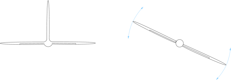
Conventional aircraft tails consist of a horizontal and vertical stabiliser at right angles to each other, as well as their respective control surfaces, the elevator and rudder. The elevator provides for the control of pitch, while the rudder provides for the control of yaw. Both the pitching and yawing forces combine to give a resultant force, the magnitude of which is given by Pythagoras’ theorem. The magnitude of the resultant is always less than the sum of its pitching and yawing components, a fact which infers that the same force can be achieved with a lesser area of aerofoil. It is for this reason that a more efficient device is sought. A single aerofoil in the correct orientation will always be able to produce the same lift force while incurring a much lower penalty in drag. It is for this reason that deploying a rotatable aerofoil (Fig. 1), precisely in the direction in which lift is required, is contemplated as an alternative to the conventional tail.
The function of the vertical stabiliser, is to maintain the aircraft’s static directional stability, while rudder inputs cause the aircraft to yaw. Yawing an aircraft induces a secondary, rolling moment. It causes the outside wing to speed up, to meet the remote, free air flow at a higher incident angle (dependent on sweepback) and, consequently, to lift. It also causes the inside wing to slow down, to meet the remote, free air flow at a lower incident angle (again, dependent on sweepback) and be slightly shielded by the fueselage, thereby losing lift. The aircraft ultimately rolls in the direction of yaw, which happens to be the same direction as the bank the yaw is intended to combine with in a coordinated turn. Of course, when the tail weathervanes, the oscillatory yaw gives rise to an oscillatory version of this yaw-to-roll phenomenon, known as Dutch roll. Dutch roll is particularly problematic in wide-bodied, multi-engined aircraft with pronounced sweepback and a poorly defined, variable centre of gravity; hence higher and offset moments of inertia. Dutch roll is, nonetheless, often considered a small price to pay for the highly desireable stall characteristics produced when sweepback is combined with washout towards the wingtips. It is for this reason that a pronounced vertical stabiliser is often a feature of such aircraft and active yaw damping, by way of the rudder, may even be required. For smaller, unmanned, single-engined aircraft with a well defined and constant centre of gravity and little or no sweepback, the vertical stabiliser is of diminished importance. Examples of such aircraft would include drones, U.A.Vs. and missiles. Wingtip modifications designed to counter induced drag might be predicted to diminish the vertical stabiliser’s significance in future aircraft designs.
The rudder, itself, ordinarily gives rise to an adverse rolling moment about the longitudinal axis. This is due to its asymmetrical positioning relative to that axis, its superior position in the conventional tail configuration. The adverse rolling moment never manifests itself, however, since it is over-compensated for by the aforementioned, yaw-induced rolling moment. Ordinary v-tails, such as the V35 Beechcraft Bonanza, suffer from adverse roll too. Only inverted v-tails (such as that of the Predator drone) and tails in which the vertical stabiliser is positioned below the longitudinal axis do not suffer from adverse roll. They give rise to a moment which reinforces both the yaw-induced roll, as well as the bank the yaw is intended to combine with in a coordinated turn. Such tails have, what might therefore be termed, an advantageous roll as a bi-product. Since the tail mostly exerts a downward force during flight, an anhedral or inverted v-tail has, furthermore, the same levelling tendency as a dihedral wing, whereas the ordinary v-tail has a destabilising effect. A rotatable stabiliser should produce no adverse roll once in the correct orientation. This prediction is based on its proposed symmetrical arrangement about the longitudinal axis. A moment of adverse roll may, however, arise during the rotation of the device; unless seperate control surfaces (or the angles of attack) on either side of the axis, are adjusted in the direction of rotation.
The primary function of the horizontal stabiliser and its control surface, the elevator, is to counter the gravitational moment about the centre of pressure associated with the wing. A centre of gravity forward of the centre of pressure is an arrangement essential to the fundamental stall characteristics any aircraft must possess. Since the elevator is used to adjust the pitch of the aircraft and, therefore, the angle of attack of its wings, a secondary function of the elevator is to determine the speed of the aircraft as well as the lift force, consequently the rate of climb, or descent. When the airspeed drops below that required for the wing to produce sufficient lift, the instinctive pilot-response is for the elevator to be adjusted so as to cause the angle of attack of the wings to exceed the stalling angle. Under such circumstances, the wing is no longer a streamlined body and, since Bernoulli’s equation only applies along a streamline, the wings stall. In comparison, the rudder is mostly used to add yaw while simultaneously banking. This combination of bank and yaw produce either a coordinated turn or, should the controls be crossed, a side-slip. An insufficient rudder input will cause the aircraft to slip in the turn, while an excessive rudder input will cause it to skid. Yawing an aircraft at low airspeeds can result in the inside wing stalling and the aircraft then enters a spin, the remedy for which is an opposite rudder input. In summary, the horizontal stabiliser may be considered more important than the vertical stabiliser, barring certain aerobatic applications and spin recovery. One variation on the horizontal stabiliser theme is worthy of mention, namely the stabilator. The stabilator is a horizontal stabiliser in which the entire stabiliser becomes the control surface. An adjustable angle of attack allows the entire horizontal stabiliser to perform the function of the elevator.
What is ultimately envisaged in this research is an aerofoil whose in-flight orientation is actively adjusted by swivelling111Note the capability implied by the use of the operative word “swivelling” as opposed to “tilting”. relative to the aircraft, around an axis parallel, or approximately parallel, to the longitudinal axis (an axis designed to be approximately parallel to the relative air flow), thereby affording the aerofoil the capability of exerting a lift force in any direction about the said axis. The direction of this lift force can, furthermore, be affected continuously, for all changes. It is anticipated that such a device may be used either aft or forward of the wing and centre of gravity. That is, in either a tail or canard-wing position. The purpose of the envisaged device, is to augment, or fully replace, the conventional control mechanisms of pitch and yaw in aircraft, although more ambitious applications are not excluded. For example, the possibility of implementations in which the device might also augment, or fully replace, the function of the ailerons (a lá elevons) cannot be ignored, should the device have seperate, hinged control surfaces, on either side of the axis about which it rotates (or a split device in the instance of a stabilator-like implementation). Variations on this theme therefore may, or may not, include a split, variable pitch, a mechanism for warping, or similar, for rapid rotation at low airspeeds.
In order to explore the concept further, the conventional tail of a popular, radio-controlled, model aircraft was replaced with a rotatable stabiliser, the electro-mechanical controls of which had to be designed and implemented. To control the orientation of the stabiliser, a continuously-rotating servo was modified by way of a position encoder (variable resistor). This then fullfilled the function of a light-weight stepper motor, since one of sufficiently low mass, size and high torque could not be sourced. It was mounted as close to the aircraft’s original centre of gravity as possible, so as to preserve the aircraft’s fundamental stall characteristics. The tail and servo were connected mechanically by way of a hollow, carbon-fibre shaft, contained within a second, carbon-fibre sleeve. The sleeve allowed the hollow shaft to rotate freely and smoothly inside the tail-boom. Wiring was inserted and run along the inside of the hollow shaft, for its full length. Three slip rings were added at its forward, servo-end and three, corresponding, spring-loaded contacts were mounted on an arm attached to the servo, thereby completing an electrical supply to the tail (a second servo on the tail is needed to control the deflection of the stabiliser’s control surface). For succinctness, the function of the joystick traditionally assigned to the control of ailerons was initially replaced by that traditionally associated with the rudder pedals. Its pitch-controlling function was otherwise designed to be conventional. Convention dictates that, in the absence of any lateral displacement of the joystick, the orientation of the stabiliser and the deflection of its control surface should correspond to those of a horizontal stabiliser and its elevator, respectively. This means that for purely lateral displacements of the joystick, the orientation of the stabiliser and the deflection of its control surface correspond to those of a vertical stabiliser and rudder, respectively. From these embedded substructures it follows that small and continuous adjustments should cause the stabiliser to rotate in the opposite direction to the joystick (when viewed from aft) and the deflection of the hinged control surface is proportional to the radial displacement of the joystick from its centred position. For what, in terms of that protocol, would amount to large and contradictory rotations of the device (rotations greater than 90 ∘), the desired configuration can be more efficiently achieved by regarding its original orientation to differ by 180 ∘ from what it actually is and by reversing the sign of deflection. Once a continuous, one-to-one, conformal mapping, between the position of the controls and the rotatable stabiliser is devised, the more traditional assignment of the controls can be reverted to for the practical purposes of flight testing.
2 The Advantage Over a Conventional Tail
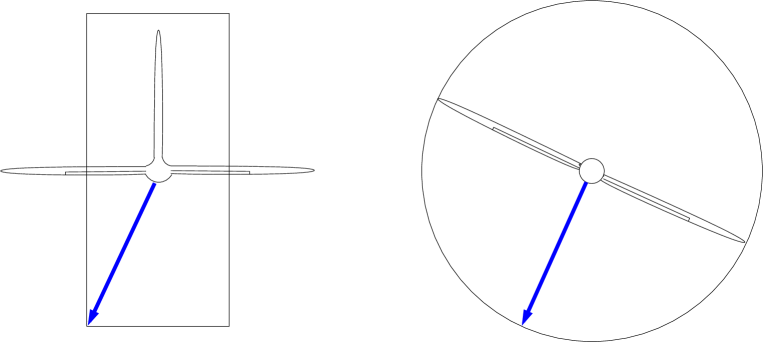
In the case of a conventional aircraft tail the envelope of maximum force is rectangular about the aircraft’s longitudinal axis (Fig. 2), it being limited to exert its maximum in only four, unique directions. In contrast, the rotatable stabiliser is able to exert this maximum in any direction, the envelope of maximum force being circular (Fig. 2).
Consider the capability of a convevtional tail, in which the vertical and horizontal stabiliser are, for simplicity, comprised of three identical members, as depicted in Fig. 2. If the area of each member is , then the maximum resultant is obtained by combining the maximum force exerted by both the horizontal and vertical stabilisers simultaneously, that is
| (1) | |||||
in which , and are the usual, density of the air, coeficient of lift and velocity of the incident air, respectively.
The above result (Eq. 1), is immediately recognizeable as the lift formula for an aerofoil of area . In this way it becomes clear that only of correctly-orientated aerofoil is required to produce the same maximum lift as a area of conventional tail. A far smaller area of aerofoil than the combined area of the horizontal and vertical stabiliser is required to produce the same force. A reduction in drag of approximately 25% is therefore one consequence of resortng to a rotatable stabiliser. The maximum capability is, furthermore, unrestricted in the case of the rotatable stabiliser, whereas the conventional tail is only able to attain this maximum in four, unique directions. The only four directions for which the conventional tail under consideration fairs this well are
radians. For a purely yaw-related requirement, the rotatable device is able to exert more than twice the force of the conventional tail, by Eq. 1. A rotatable stabiliser therefore has the advantage of being able to exert the maximum lift force in any direction, which can amount to more than twice the capability, for a much reduced drag. Of course, the individual members of a conventional tail do not operate independently from an aerodynamic point of view, they operate rather as a single system, the respective flows over each surface interacting with each other. The proposed device might therefore also be expected to facilitate a lower interference drag, there being two less intersecting surfaces.
Such an analysis is, of course, a gross over simplification and the significance of tail drag, itself, needs to be put into perspective. Drag ordinarily depends on the flight regime, the percentage of laminar flow, etc. and induced drag can also become a factor, depending on the speed of the aircraft. The relatively low aspect ratio of the device, preferred for rotation, is a disadvantage from an induced drag point of view. When it comes to parasitic drag, however, a close in engine installation, gear doors and a plethora of other factors are by far the greatest budget of drag on the airframe, the largest contributors to the overall drag. Interference drag, cooling drag and propeller effects in the absence of laminar flow are just a few of the other issues which bring the significance of tail drag into perspective.
Possible disadvantages of a rotatable device are that there is a limit on response time, as will be shown, and a rotating link might exceed the mass of the conventional system of cables and pulleys. In a manned aircraft the response of the normal tail configuration is instantaneous, at least in so far as the human input is. In a remotely controlled aircraft one relies on servos etc. anyway.
3 Mechanical and Electrical Modification of a Radio-controlled, Model Aircraft
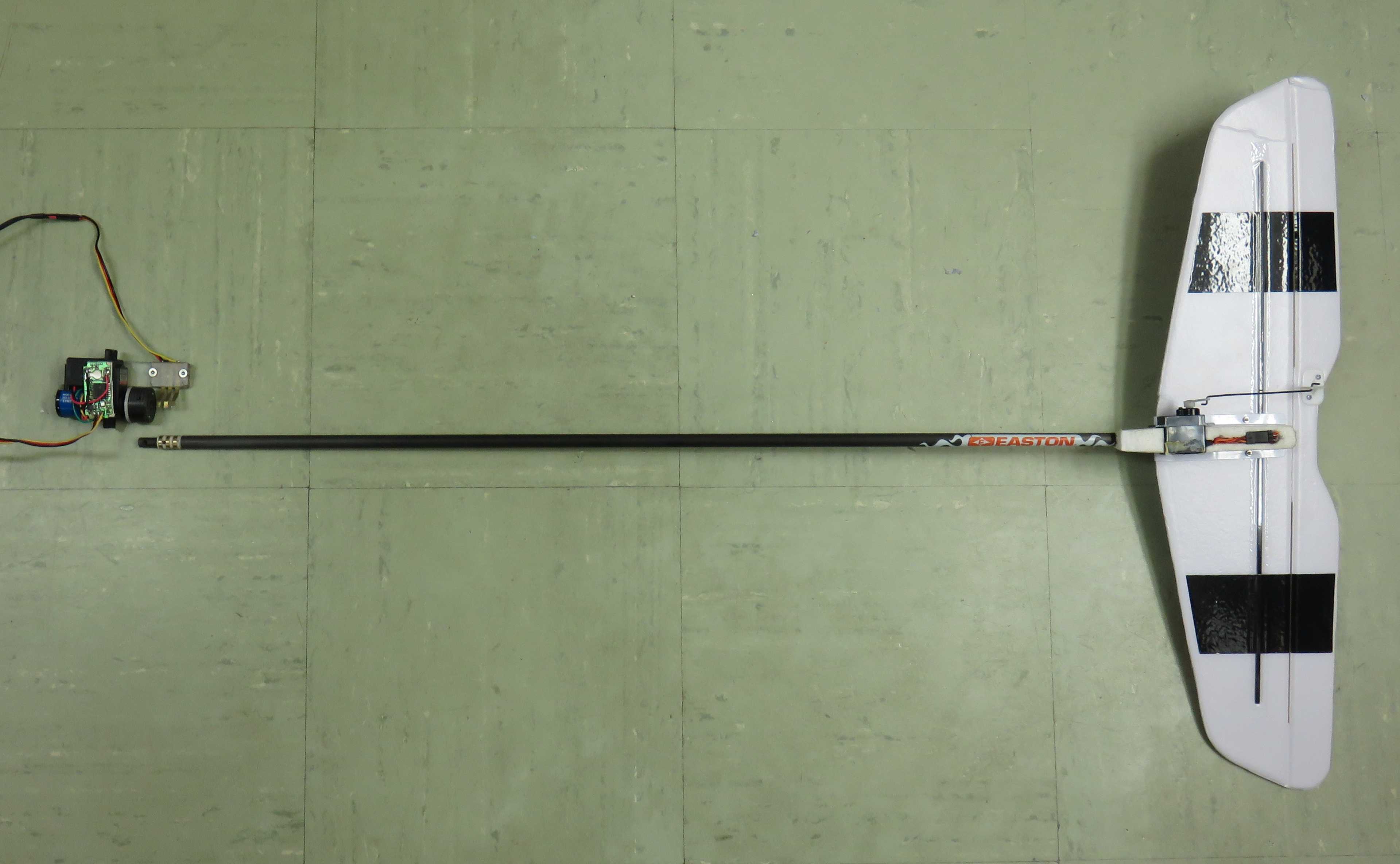
The vertical stabiliser of a popular, radio controlled, model aircraft (the Radian Pro) was removed and its tail-boom drilled out. A hollow, carbon-fibre sleeve, which was chosen to accomodate a second, inner, carbon-fibre shaft in such a manner as to allow its free rotation, was inserted into the tail boom. The original horizontal stabiliser was attached to the back of the internal, rotating shaft while the front of the shaft was attached to a modified servo at the forward, cockpit end (refer to Fig. 3). The carbon-fibre shafts allowed the modified servo to be positioned as close to the aircraft’s original centre of gravity as possible (so as to preserve the aircraft’s fundamental stall characteristics) while simultaneously providing a mechanical connection to the tail.
A stepper motor of sufficiently low mass, size and high torque could not be sourced and so a continuously-rotating servo, modified by way of a position encoder, or variable resistor, was used as a light-weight substitute to fulfill the task of rotating the stabiliser (refer to Fig. 4). The effect of incorporating a 5 , three turn, rotary potentiometer produced a 180 ∘ clockwise and 180 ∘ counter-clockwise rotation, with feedback. The rotating head of the modified servo was altered to feature a chuck, designed to accomodate the tip of the carbon-fibre shaft, held in place with a grub screw. Three, spring-loaded electrical contacts were also mounted on an arm attached to the servo.
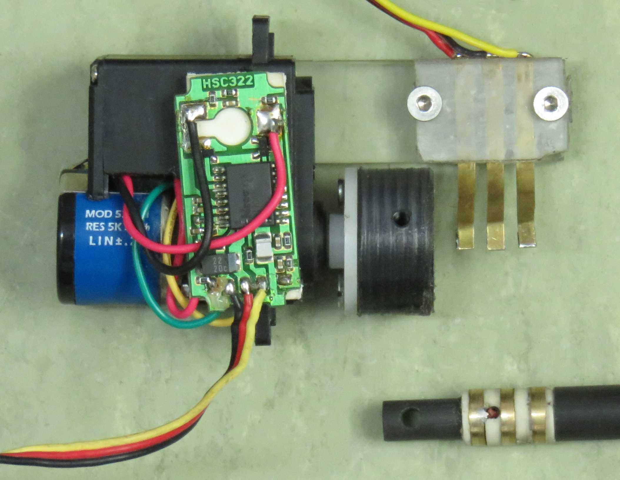
Inserting wiring along the full length of the innermost, hollow, carbon-fibre shaft and incorporating three slip rings into its collar, so as to push against the three, spring-loaded electrical contacts, facilitated an electrical supply to the tail (refer to Fig. 4). The purpose of the electrical wiring is to supply the servo which controls the deflection of the stabiliser’s hinged, control surface.
A standard, remote-control (RC) radio receiver was used to receive the signal from the transmitter. It passes the transmitter-joysticks’ position, by way of a pulsed width modulation (PWM) signal, to the integrated circuit (IC). The integrated circuit has multiple IO lines, 14 of programme memory and a Microchip PIC16F876 microcontroller (Fig. 5) computes the desired output signals for the orientation of the rotatable stabiliser and the deflection of its control surface. An eight-pin IC-socket was included in the circuit to facilitate the connection of a debugger. The circuit has two inputs and two outputs. Both inputs are connected to the radio receiver. The microcontroller converts information on the joystick’s position into an orientation of the stabiliser and deflection of its control surface. This is, in turn, converted to two outputted signals, one for each servo. The outputted signals are sent to the respective servos which control the orientation and deflection. The output signals use the same PWM principle as the input signals. They consist of a high pulse followed by a low pulse, the total duration of which is 20 , from start to start. The duration of the high pulse varies from a minimum of 1 , to a maximum of 2 .
It would have been preferable, though not practical, to place the stabiliser higher up, further out of the downwash. A low and far back horizontal stabiliser has been implicated as a cause of flat spins by some Langley, spin-tunnel tests.
A summary list of the equipment, mechanisms and materials used in the modification would therefore be as follows:
-
1.
Radian Pro Glider.
-
2.
Continuously rotating servo
-
3.
Vishay wirebound potentiometer (533 Series, three turn, 5 ).
-
4.
Microchip PIC16F876 microcontroller.
-
5.
Two carbon-fibre arrow shafts (one to fit within the other, loosely enough so as to allow free rotation).
-
6.
Wiring.
-
7.
Spektrum DX7S Radio.
-
8.
Rod end, aluminium strips and pipe (for a stand, for testing).
4 Design for the Control of a Rotatable Stabiliser
This section sets out to design a protocol for the control of a rotatable stabiliser, such that its in-flight orientation and the deflection of its control surface can be actively adjusted in an intuitively obvious manner.
4.1 Desired Mapping and its Implied Control Protocol
Since the configuration of a rotatable stabiliser involves two degrees of freedom, namely its orientation and the deflection of a hinged control surface (or its angle of attack, for an all-moving, stabilator-like device), any two-axis device will suffice as a controller. For succinctness, a mapping betweeen states of the stabiliser and the position of the simplest two-axis controller (a joystick) is formulated. The function of the joystick traditionally assigned to the control of the ailerons is replaced by that traditionally associated with rudder pedals, for simplicity and ease of understanding. Its pitch-controlling function is otherwise conventional. There is no loss of generality in making this joystick-only simplification. Pedal inputs can just as easily be substituted for the lateral movements of a joystick. The mapping is readily converted to the more conventional controls for pitch and yaw, in either manned aircraft, or radio-controlled aircraft. What follows is a description of how a continuous, one-to-one, conformal mapping, between the position of controls and the state of the rotatable stabiliser, can be devised in order for it to be controlled logically, reflexively and in an elementary and intuitively obvious manner.
4.1.1 Embedded Substructures Within the Domains
Convention dictates that the joystick retains the traditional pitch-altering function of the aircraft. This requires that in the absence of any lateral displacement of the joystick, the orientation of the stabiliser and the deflection of its control surface should correspond to those of a horizontal stabiliser and its elevator, respectively. The preferred orientation of the rotatable stabiliser is therefore parallel to the lateral axis of the aircraft for pitch-only inputs from the joystick. What is traditionally the banking function of the joystick is, however, replaced by the yaw-adjusting function traditionally assigned to the rudder pedals (this is the traditional mode four on most radio-control apparatus). This means that for purely lateral displacements of the joystick, the orientation of the stabiliser and the deflection of its control surface correspond to those of a vertical stabiliser and rudder, respectively.
Fig. 6 relates the orientation of a rotatable stabiliser and the deflection of its hinged control surface to positions of the controls. The circle in Fig. 6 represents the boundary of the domain of any two-axis controlling device e.g. a joystick, or a combination of one axis of a joystick and pedals. Superimposed at four positions on it are the corresponding states of a rotatable stabiliser as seen from aft. Starting from the top of Fig. 6 and moving clockwise: Stick forward, nose pitches down; right pedal or stick, nose yaws right; stick back, nose pitches up; left pedal or stick, nose yaws left.
4.1.2 The Control Protocol which Stems from the Embedded Substructures
A logical outgrowth of the two embedded substructures (Fig. 6) is that small and continuous adjustments cause the stabiliser to rotate in a direction opposite to that of the joystick (when viewed from aft) and the deflection of the hinged control surface is proportional to the radial displacement of the joystick from its centred position. The blue arrows in Fig. 6 indicate the sense of rotation (no translation) between the respective states.
For movements of the controls through the origin, or close to it, it may be preferable to reverse the sense of deflection, rather than have the device rotate excessively. Unproductive and excessive rotation due to small, repetitive corrections and over-corrections can be avoided, in this way. Unproductive and excessive rotation can readily be defined as adjustments of the joystick which require rotation greater than 90 ∘. The proposed remedy is to rotate the device as if its orientation differs by 180 ∘ and to reverse the deflection to be the negative of what it otherwise would have been. Deflection of the hinged control surface is, therefore, not always to the same side, requiring the use of a symmetrical aerofoil.
A more exact formulation of the control protocol follows. Suppose and are used to denote the horizontal displacement of a joystick and, , its angular coordinate. Notice that, if is used to denote the change in this angular coordinate (), then can always be converted to a periodic equivalent, by implementing
| while |
recursively, to insure that . The proposed deployment of the device can then be formulated as follows:
-
1.
The orientation of the aerofoil and the deflection of its control surface correspond to those of a horizontal stabiliser and elevator, respectively, for positions of the joystick on the line . The orientation of the stabiliser and the deflection of its control surface correspond to those of a vertical stabiliser and rudder, respectively, for positions of the joystick on the line and .
-
2.
For small and continuous adjustments of the joystick (the category ) the aerofoil rotates in the opposite direction to the joystick, when the former is viewed from aft. The relation
is one in which the orientation, , of the aerofoil’s lift force can be rotated evenly to starboard and port.
-
3.
The deflection of the hinged control surface (or the angle of attack in the case of a stabilator-like implementation) is proportional to the radial displacement of the stick from the centred position. If is used to denote the deflection of the control surface, then it is related to the position of the joystick by
in which is some constant which callibrates the deflection of the aerofoil to the displacement of the joystick.
-
4.
For adjustments of the joystick which militate a rotation greater than 90 ∘ in terms of the aforementioned protocol, expedience dictates that it be applied as if the actual orientation of the device differs by 180 ∘ from what it actually is and the sign of deflection be reversed. That is, if , then
The above strategy becomes clearer when contemplating the alternative formulation,
in which is the old orientation of the aerofoil.
Notice that however tempting it may be to exploit as a variable with which to further simplify these formulae, the idea is to rapidly recalculate the stabiliser’s configuration (at 25 times per second), before the previously calculated configuration has actually been achieved. The above formulae were incorporated into a programme that was written using the Microchip MPLAB IDE software, which utilizes the Microchip XC8 C compiler. The microcontroller was programmed and debugged using the Microchip ICD2 debugger. The debugger enabled the programme to be stepped through line by line.
In the conventional tail, two linearly independent inputs are mapped to two linearly independent outputs, which combine to give a resultant. In the rotatable-stabiliser concept the two linearly independent inputs are mapped directly to a resultant. Notice that the transformation between states is continuous, conflicting, successive control inputs being the exception. Clearly, there would be a fundamental loss of continuity in the aforementioned diagrams, were a tilting, as opposed to a fully rotating device to be used.
Mistakenly rotating such a device into the vertical position represents a very real danger at low altitudes. One, contemplated safety precaution was to restrict the -axis input so that the device is never tilted at an angle greater than e.g. 27 ∘ to the horizontal. This can easily be accomplished by implementing the formula
to restrict and modify the -input from the joystick.
Pedal inputs can just as easily be substituted for the lateral movements of a joystick, thereby converting the mapping to one associated with the more conventional controls for pitch and yaw in manned aircraft. Likewise, the mapping can also be readily converted to one associated with the more conventional controls for pitch and yaw in radio-controlled aircraft, simply by switching the transmitter, from its mode 4, to its mode 2.
5 Rapid Rotation at Low Speeds and its Implications for the Angle of Attack
One, anticipated handicap of a rotatable stabiliser is the potential for it to stall, from its tips, inward, if rotated too fast. Once rotation is underway, the angle of attack is no longer simply that between the chord and the remote, free air flow. Under such circumstances the incident air acquires an additional component of velocity, opposite to the direction of rotation. Rapid rotation of the device could therefore be a complication in slow moving aircraft. Rotation of the device at maximum deflection (the stalling angle) could, likewise, be predicted to be problematic. The outer tip of the aerofoil will begin to stall during rotation, should rotation cause the maximum angle of attack to be exceeded. Either the aerofoil must be rotated at a slower speed or a differential angle of attack must be added and subtracted from either side of the axis of rotation.
The deviation in the angle of attack, , brought about by rotation is readily calculated according to the formula
| (4) | |||||
in which the radius referred to is the distance along the aerofoil from the point of rotation. From this formula one immediately observes that short spans are conducive of small deviations in the angle of attack, as are the kind of high airspeeds one normally associates with missiles and their like. The area, hence lift, lost in shortening the span can, to a certain extent, be recouped by means of a longer chord.
For a radio controlled aircraft with a rotatable stabiliser of 40 and a 16 stall speed, one would expect rotation at a rate of to induce a departure from the angle of attack, at the tips, which would never exceed 4 ∘. What kind of stalling angles are contemplated? Symmetrical aerofoils with a high stalling angle, such as the NACA 0015, are a common choice for stabilators. In theory this aerofoil stalls just above 22 ∘ while simultaneously delivering a lift coefficient just greater than 1.5 and a lift-to-drag ratio slightly above 95 (Jacobs et al. [4]). In the real world induced drag and atmospheric conditions, e.g. wind shear and gusting, can dramatically reduce this angle and the margin of safety. The functional range of angles of attack for aerofoils, in general, is usually cited as being in the -4–16 ∘ range by more practical references concerned with less ideal conditions (e.g. Thom [5]). It was decided to set the rate of aerofoil rotation to just over (15 ) in the radio-controlled, model aircraft.
6 Testing the Rotatable Stabiliser
The first stage of testing involved the completed aircraft simply being suspended from a tether and being subjected to its own propwash (refer to Fig. 7).
Thereafter the model aircraft, sans wings, was attached by way of a cradle, to a rod-end (or universal joint), thereby allowing it to be either mounted above a car (driven at around 30 ) or placed in a make-shift wind tunnel (the entrance to a hospital air-conditioning unit). This was to test and familiarise the authors with the controls. The third stage of tests involved re-attaching the wings and flying the aircraft. The device was initially tested using mode 4 of the radio. This was subsequently changed to mode 2 for the flight tests.
7 Results
The modified, radio-controlled aircraft flew successfully and its performance lived up to the authors’ best expectations. Surprisingly, no side effects arising from the omission of a vertical stabiliser were evident and the flight of the modified, model aircraft did not seem to be impaired by its absence. The drag on the tail seemed to be sufficient for the purposes of static longitudinal and directional stability.
The orientation of the stabiliser is clearly visible, as the aircraft turns to starboard, in the Fig. 8, clockwise sequence. The orientation of the stabiliser is also clearly visible, as the the aircraft performs a steeper, aerobatic turn to starboard, in the Fig. 9, clockwise sequence. The Fig. 10, winding sequence depicts a turn to port. The Fig. 11 sequence shows a purely yaw-induced bank to port (no aileron), at the end of which the control surface unexpectedly detaches under the stress.
8 Conclusions
This research implements a design for the control of a rotatable stabiliser which, it is proposed, might augment, or fully replace, the conventional mechanisms for pitch and yaw in certain types of aircraft. The anticipated advantages of such a device are around 25% less drag, for a capability which ranges between equivalent, to greater than twofold that of the conventional tail (refer to Eq. 1 and Fig. 2). Interference drag should also be eliminated.
Whether the controls are a single joystick, two joysticks, or a combination of joystick and pedals as in manned aircraft, their relevant position may be described by two coordinates, and . A change in their angular coordinate can always be expressed in a format , by implementing
| while |
recursively, for initially assumed to be from . The two modes of control implemented are then as follows: If , the orientation of the aerofoil, , and the deflection, , of its control surface are calculated according to
Otherwise, if , the configuration of the stabiliser is calculated according to
The result is that, for a pitch-only input, the orientation of the stabiliser and the deflection of its control surface correspond to those of a horizontal stabiliser and its elevator, respectively. Conversely, for a yaw-only input, the orientation of the stabiliser and the deflection of its control surface correspond to those of a vertical stabiliser and rudder, respectively. Small and continuous adjustments cause the aerofoil to rotate in the opposite direction to the controls (when viewed from aft) and the deflection of the hinged control surface is proportional to the radial displacement of the joystick from its centred position. For what, in terms of that protocol, would amount to large and contradictory rotations of the aerofoil (rotations greater than 90 ∘) the desired configuration is more efficiently achieved by regarding its original orientation to differ by 180 ∘ from what it actually is and by reversing the sign of the deflection. This second mode of control obviously implies the use of a symmetrical aerofoil, such as the NACA 0015. This should not be a cause for concern, however, since the NACA 0015 has an almost identical performance to that of the NACA 2412 (Jacobs et al. [4]), the latter being the preferred choice in many Cessnas. The algorithm to determine the aerofoil’s orientation and the deflection of its control surface was run 25 times per second.
One, anticipated handicap of such a device is the potential for it to stall, from its tips, inward, if rotated too rapidly. The deviation in the angle of attack, , brought about by a rapid adjustment can be calculated according to the formula
in which the radius referred to is the distance along the aerofoil from its axis of rotation. A restriction on the speed of rotation therefore exists and a strategy in which the device is never rotated with its control surface at maximum deflection is obviously prudent. The rate of the aerofoil’s rotation was set to just over (15 ) in the radio-controlled model. This was slow enough to prevent any noticeable, outboard stalling, yet fast enough to prevent any noticeable lag in control. No problems were encountered in the radio-controlled model, however, the danger of a large-span stabiliser stalling, from its tips, inward, at low airspeeds during rotation, make the device ideally suited to high speed aircraft, missiles and drones. The former pair are both craft in which either a short tail-span or fins are preferred. A high-performance response is usually not required from drones and their tendency not to engage in rapid aerobatic manoeuvres should permit slow rotation, making them just as likely candidates for the implementation of a rotatable stabiliser. In a manned aircraft the response of the normal tail configuration is instantaneous, at least in so far as the human input is. In a remotely controlled aircraft one relies on servos, anyway. Setting a different pitch on either side of the axis of rotation, or even incrementally warping the aerofoil along its full length, should that be possible, would be one counter measure to the problem of stalling at the tips during rotation.
No weathervaning of the tail, something which ultimately manifests itself as Dutch roll, was observed in the many flights of the radio-controlled, model aircraft. It should, however, be emphasised that the model aircraft’s wing had no, or little sweepback (curved along the leading edge) and a small amount of in-flight dihedral. The radio-controlled aircraft’s small scale, low speed and, consequently, the low Reynolds number of the airflow around it severely limit the extrapolation of these results to large, fast aircraft, missiles and even drones. Although the radio-controlled aircraft appeared to demonstrate good, inherent, static longitudinal and directional stability, intensive experimentation would obviously be required before the deployment of such a device in any civil aircraft could be contemplated.
The ever-present danger of a pilot inadvertantly making a yaw-only input is a real concern. Rotating the aerofoil into the vertical at low level has obvious consequences. Devising and programming a precautionary control strategy against such an eventuality is, nonetheless, no insurmountable obstacle, to the extent it might, more aptly, be considered a topic for further experimentation and debate, rather than one of research. A very minor, nonetheless, important problem, a solution is necessary. The precautionary mode, whereby the -axis input is restricted to
(so that the device is never tilted at an angle greater than 27 ∘ from the horizontal), had the unpleasant side-effect of disabling all yaw control, from time to time. It was found to be too restrictive and abandoned. Another, untested alternative would be to stipulate a minimum -axis input, to be triggered by yaw-only inputs. A myriad of options, with variations in a conflated pitch input whose decay ranges from linear to exponential, exist. The inherent danger obviously diminishes as an aircraft’s design approaches that of a so-called flying-wing (e.g. the radio-controlled Wombat, the more extreme Horten Ho 229 or Northrop-Grumman X-47B), envisaged by many to be the future of aviation. In view of the alarm expressed at this work from certain quarters, it should also be pointed out that the Horten Ho 229 reportedly only suffered from moderate lateral instability and videos of the Northrop-Grumman X-47B are not suggestive of any instability at all. This in the complete absence of any stabilisers at all! Wingtip modifications designed to counter induced drag might also be predicted to diminish the vertical stabiliser’s significance in future aircraft designs.
Although the modified servo’s limitation of was never encountered during any of the test flights, that limitation would easily be eliminated by the deployment of a stepper motor, in conjunction with a shaft encoder, in a slightly larger aircraft. A limit of finite rotation could be a very real risk to any aircraft of value. Were a tilting, as opposed to a rotating device to be used, there would clearly be a fundamental loss of continuity in the movement of the device and therefore the control of the aircraft. In the case of a 90 ∘-tilting device, for example, one cannot effect a continuous transition between a nose-up to nose-down input, while simultaneously maintaining a yaw input, as this results in a lateral inversion of the yaw.
Although it is contended that the mapping betweeen states of the device and the position of a single, two-axis controller (e.g. a joystick) is the most logical, it was found that even the best radio-pilots could not overcome their reflexes. The mapping was readily converted to the more conventional controls for pitch and yaw in radio-controlled aircraft; that is, implemented under the standard mode two of the radio, rather than its mode four. Pedal inputs can similarly be substituted for the lateral movements of a joystick.
The Parkzone Radian Pro was selected on the basis of it being fairly ubiquitous. This may not have been the most astute choice, in retrospect, since its flexibility often led to an elastic response and the tailboom meant that the stabiliser had to be placed close to downwash. It would also have been preferable not to have positioned the device in the propwash. The Skysurfer may have been a better choice.
The only difference between a canard-wing type deployment and the tail implementation which is the topic of this work, would be that the deflection of the hinged control surface is in the opposite direction. For a stabilator-like device, the specified deflection relates to the trailing edge, instead of a hinged control surface. In helicopters the tail consists of a rotor with pitch and speed control, which complicates matters only very slightly. In such circumstances the direction of the deflection can be taken to specify the direction of thrust, instead. While the concept of directed lift is presently developed in the context of an aerofoil, an analogous description for a rotor is easily deduced. If one were to coin a term for a whole family of such devices e.g. ‘swivelator’ it would refer to an aerofoil (or rotor) whose in-flight orientation is actively adjusted by swivelling333Note the capability implied by the use of the operative word “swivelling” as opposed to “tilting”., relative to the aircraft, around an axis parallel, or approximately parallel, to the longitudinal axis, thereby affording the device the capability of exerting a lift force in any direction about that axis. The magnitude of the lift force is designed to be adjustable by way of a hinged control surface, changing the angle of attack (a lá a stabilator), or additionally, in the case of a rotor blade, spinning faster or changing the pitch of the rotor blades. Aileron-like inputs might also be superimposed (as in elevons) in implementations where the rotatable stabiliser has separate control surfaces on either side of the axis about which it rotates.
9 Acknowledgements
Michael Mettler, Pieter Botes and Adriaan Hugo provided work-shop assistance. The authors are indebted to Reynard Myburgh and Danie Krugel for assistance in putting the radio-controlled, model aircraft through its paces. Johan Meyer and Glen Taylor are also deserving of thanks.
References
- [1] S. Childs. Swivelator. Provisional patent 2004/7616. 2004.
- [2] S. Childs. Swivelator. Provisional patent 2004/10179. 2004.
- [3] S. Childs. Swivelator. Provisional patent 2005/05287. 2005.
- [4] E.N. Jacobs, K.E. Ward, and R.M. Pinkerton. The characteristics of 78 related airfoil sections from tests in the variable-density wind tunnel. Technical Report 460, National Advisory Committee for Aeronautics, 1933.
- [5] T. Thom. The Aeroplane – Technical, volume 4 of The Air Pilot’s Manual. 1993.
Appendix
Notation
| Symbol | Description |
|---|---|
| coeficient of lift | |
| deflection of the hinged control surface | |
| constant callibrating the deflection of the aerofoil | |
| to the displacement of the joystick | |
| area | |
| velocity of the incident air | |
| lateral displacement of the joystick, or pedal input | |
| longitudinal displacement of the joystick | |
| change in the angle of attack | |
| angle between the stabiliser and the lateral axis | |
| old orientation of the stabiliser | |
| density of the air | |
| angular coordinate of the joystick’s position | |
| previously recorded angular coordinate of the joystick |
Algorithm
The programme for the control of the rotatable stabiliser, written in C, is as follows.