Room-Temperature Quantum Memory for Polarization States
Abstract
An optical quantum memory is a stationary device that is capable of storing and recreating photonic qubits with a higher fidelity than any classical device. Thus far, these two requirements have been fulfilled in systems based on cold atoms and cryogenically cooled crystals. Here, we report a room-temperature quantum memory capable of storing arbitrary polarization qubits with a signal-to-background ratio higher than 1 and an average fidelity clearly surpassing the classical limit for weak laser pulses containing 1.6 photons on average. Our results prove that a common vapor cell can reach the low background noise levels necessary for quantum memory operation, and propels atomic-vapor systems to a level of quantum functionality akin to other quantum information processing architectures.
A readily available, technologically simple, and inexpensive platform for optical quantum memories is the cornerstone of many future quantum technologies Kimble2008 ; Lvovsky2009 ; Bussieres2013 ; Northup2014 . The practical implementation of such devices is fundamental to realizing deterministic logic gates for optical quantum computing Fan2012 ; Monroe2014 , and creating quantum repeater stations that overcome the current distance-limits of quantum key distribution DLCZ . A robust and truly scalable architecture may benefit from room-temperature, easy-to-operate quantum light-matter interfaces. Despite much progress Maurer2012 ; Saeedi2013 ; Eisaman2005 ; Reim2011 ; Hosseini2011_2 ; Sprague2014 , the storage of qubits in a room-temperature system has not yet been demonstrated Novikova2011 .
Room-temperature systems have shown much promise towards advanced optical technologies with progressions such as the miniaturization of vapor cells Baluktsian2010 and their integration into photonic structures for applications like light slow down Ghosh2006 , four-wave mixing Londero2009 , cross-phase modulation Venkataraman2013 and storage Sprague2014 . Furthermore, a warm vapor alleviates the need for laser trapping and cooling in vacuum or cooling to cryogenic temperatures.
The storage of light in atomic vapor can operate with high efficiency (87%) Hosseini2011_1 , large spectral bandwidth (1.5 GHz) Reim2010 and storage times on the order of milliseconds Novikova2011 . Vapor systems have proven their ability to preserve non-classical properties in the storage and retrieval of quantum light states Novikova2011 . In regard to qubits, polarization states were shown to be stored with high fidelity in experiments involving bright light pulses Cho2010 ; England2012 . However, complete quantum memory operation [i.e. storage of polarization qubits] using warm atomic vapors has yet to be achieved Novikova2011 due to large control-field-related background photons constraining the signal-to-background-ratio (SBR) during retrieval.
Here we demonstrate the first room-temperature implementation of an optical quantum memory for qubits, by mapping arbitrary polarization states of light into and out of a warm rubidium vapor. The memory performance is tested with weak coherent pulses containing on average 1.6 photons. The average fidelity is measured to be 71.5 1.6%, with qubit coherence times on the order of 20 µs. We also show a detailed analysis of the background noise and its influence on the quantum memory fidelity.
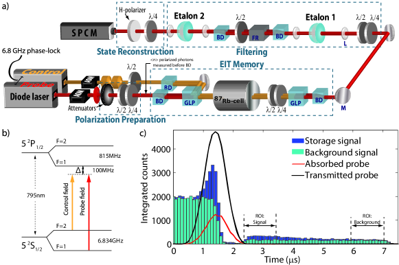
To store a polarization qubit of the form cossin (where and refer to horizontal and vertical polarization states and and correspond to the polar and azimuthal angles on the Poincaré sphere, respectively), we map the photonic polarization mode onto two spatially separated atomic ensembles concurrently under conditions of electromagnetically-induced transparency (EIT), in a single 87Rb vapor cell at C, containing Ne buffer gas (Figure 1a).
We employed two external-cavity diode lasers phase-locked at 6.8 GHz to resonantly couple a Lambda configuration composed of two hyperfine ground states sharing a common excited state. The probe field frequency is stabilized to the transition at a wavelength of 795 nm (red detuning =100 MHz) while the control field interacts with the transition.
The pulse shapes for both the probe and control fields are independently controlled with acousto-optical modulators. Two polarization beam displacers are used to create a dual-rail set-up allowing simultaneous light-storage in both rails. A set of polarization elements supply 42 dB of control field attenuation while maintaining 80% probe transmission. Furthermore, two monolithic, temperature-controlled etalon resonators provide a further 102 dB of control field extinction. Both etalons have a thickness of 7.5 mm, radius of curvature of 40.7 mm, free spectral range of 13.3 GHz, finesse of 310 and transmission linewidth of 43 MHz. Together they achieve 16% probe transmission. In between the etalons we have implemented a polarization insensitive Faraday isolator in order to suppress any back reflections off the etalon surfaces (transmission 50 %). Overall, our setup achieves 144 dB control field suppression while yielding a total 4.5% probe field transmission, hence exhibiting an effective, control/probe suppression ratio of 130 dB.
Storage experiments are performed with 1 µs long probe pulses containing 1.6 photons for six different input polarizations (, , , , , , forming three mutually unbiased bases of the qubit Hilbert space. The resulting histograms of photon arrival times at the detector contain information regarding both the storage process and events associated to the control-field induced background (storage histogram, blue in Fig. 1c).
In order to determine the storage efficiency () we integrate the number of counts over the region of interest (ROI) corresponding to the retrieved pulse (from 2.4 to 3.4 µs in Fig. 1c) and subtract the number of counts from a signal-free region of the same histogram (from 6 to 7 µs in Fig. 1c). The efficiency is then calculated by comparing this difference in counts to the total counts in the transmitted probe through the filtering system without atomic interaction (black line in Fig. 1c). The signal to background ratio is obtained in a similar fashion using the counts integrated over the same ROI in the storage histogram (signal+background) and the number of counts over a signal-free region in the same histogram (background). Our SBR is then calculated as [(signal+background)-(background)]/(background) for each polarization input.
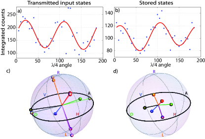
The polarization states retrieved from the EIT memory are evaluated using a polarimeter consisting of a quarter-wave plate and polarizer situated after the final filtering stage (see Fig. 1b). Rotating the quarter-wave plate causes oscillations in the intensity measured after the polarizer (within the previously defined ROI), from which we obtain the Stokes vectors (, normalized by ) through a fitting (see Fig. 2a-b) Berry1977 .
The complete evaluation of the polarization fidelity is performed in four steps: First, we measure the Stokes parameters of our input probe polarization entering the first beam displacer. Second, we perform the same procedure for pulses that have propagated through the entire setup (cell included) and the filtering stages in the absence of EIT conditions (see Fig. 1c, red line). Third, we estimate and apply the unitary rotation to the original input states due to all optical elements by using a least squares fit method which fits them to the transmitted states without changing their lengths (see Fig. 2c).
The fidelity between the rotated inputs () and the transmitted states was greater than 99% on average (green dots in Figure 3a). This step can alternatively be achieved in the system using linear optical elements. Lastly, we perform a polarization analysis of the retrieved pulses () which are then compared directly to the rotated input states to obtain a fair estimation of fidelity with respect to the original input states. The fidelity is evaluated as . We note this procedure is equivalent to utilizing the corresponding density matrices Altepeter2005 .
In Figure 2d, the Poincaré sphere associated with the retrieved states clearly shows orthogonal but shortened vectors (as compared to the input) due to the influence of decoherence processes and the uncorrelated background counts. Table 1 summarizes the storage efficiency, SBR, and fidelity reconstruction for all the polarization inputs for . We see an average fidelity of 71.5 1.6%, clearly surpassing the classical limit of 66%.
| Input | H | V | D | A | R | L | Average |
| SBR | 1.68 | 1.1 | 1.27 | 1.15 | 1.53 | 1.38 | 1.35 .09 |
| Fidelity (%) | 71.3 | 79 | 69.2 | 71.4 | 70.2 | 67.6 | 71.5 1.6 |
| Efficiency ()(%) | 7.9 | 5.3 | 4.6 | 3.8 | 5.6 | 5.9 | 5.5 .6 |
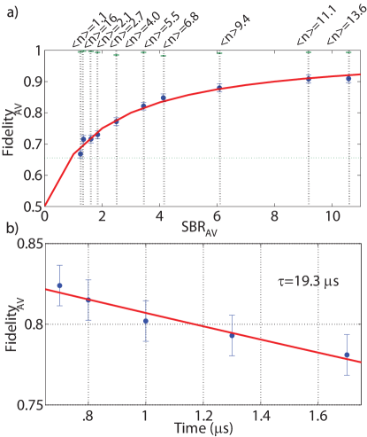
To quantify the influence of the background on the fidelity of the qubit memory, we have performed a series of polarization measurements (using the ROI as before), where we modify the SBR by increasing the input photon number (see Figure 3a). We can see that an average fidelity of 90% can be achieved at a SBR of 8.0. The scaling of SBR can be understood with a theoretical model considering a dual-rail optical quantum memory based on two atomic ensembles, with each ensemble assumed to be a Poissonian source of uncorrelated signal and background photons.
We assume that each of the ensembles stores one of the two polarization components with efficiency before recombination and read out. The probability of producing signal photons and background photons (for both ensembles) is and respectively. Here is the average number of input photons, and is the average number of background photons. Note that two ensembles emitting Poissonian noise with mean photon number into the same spatial mode behave as one noise source with mean photon number .
In the instance of signal and background photons being produced, the probability of detecting a signal photon is simply , and of detecting a background photon is for non photon-number resolving detectors. Then, in general, the probabilities of detecting up to order signal and background photons are
and the fidelity is
The theoretical estimation for the fidelity scaling (solid red line in Fig. 3a) has been calculated using independently measured parameters =0.055 and (see Figs. 4a-b).
Additionally, we have also measured the coherence time of the qubit storage. Figure. 3b shows the decay time of the quantum memory for the case =6, showing a time of 19.3 µs.
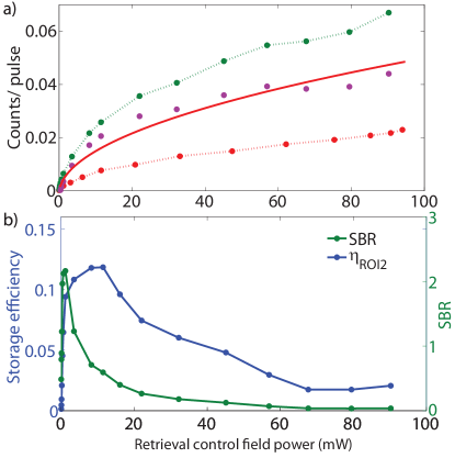
Furthermore, we experimentally characterize the background noise. To do so we integrate the number of counts in the ROI of histograms corresponding to measurements of only the background (cell present, control field only, green dots in Fig. 4a) and only the technical background (control field only, no cell, red dots in Fig. 4a) and divide by the number of experimental runs. This provides the number of background counts per retrieved pulse. We repeat this procedure for several values of the control field power.
We can see that the total background is composed of photons from both leakage of the control field (technical background) and those generated by spontaneous emission and four-wave mixing (FWM) processes Phillips2011 ; Lauk2013 . Background photons due to FWM originate from unprepared atoms in the storage region that are pumped to the F=1 ground state by the control field during retrieval. The number of resulting FWM photons should then scale as (or the square root of the control field power), where is the Rabi frequency of the control field. The purple dots in Fig. 4a show the resultant of the technical counts subtracted from the background and the red line is a fitting of a function , suggesting that our background is dominated by the the FWM mechanism.
Lastly, we analyze the behaviour of the storage efficiency in the ROI (, blue dots in Fig. 4b) and SBR (using the same ROI, green points in Fig. 4b) as a function of the control field power. We can see that the efficiency has a substantially different scaling than the SBR and that their maxima do not match. We notice that while our setup is capable of maximum storage efficiencies of 16% (over a larger ROI), the ideal signal to background value for quantum memory functionality corresponds to suboptimal storage efficiencies.
In summary, we have presented the first, to our knowledge, room-temperature optical quantum memory system capable of storing arbitrary polarization states. We have demonstrated an average fidelity of 71.5 1.6% and storage lifetimes of 20 micro-seconds. We have also investigated the influence of the background in the fidelity of the qubit memory and provided a model explaining the scaling of fidelity with signal-to-background ratio. These measurements demonstrate that a six-fold decrease in background is still necessary for our current implementation to operate simultaneously at higher fidelities and with maximum efficiencies. This could be achieved by using an additional re-pumper scheme Jang2006 or by modifying the one-photon detuning of the laser system. Longer coherence times can be achieved by adding paraffin coating to our current cells Balabas2010 . We believe that the present system has the potential to be implemented on a grand scale and thus paves the way for the creation of novel quantum repeaters and networks based on truly scalable architectures.
We thank A. I. Lvovsky and A. J. MacRae for sharing their etalon design. This work was supported by the College of Arts and Sciences and the Office of the Vice President for Research of Stony Brook University. The authors kindly thank G. Rempe, S. Ritter, A. Neuzner, J. Shupp and A. Reiserer for useful discussions.
References
- (1) H. J. Kimble, Nature 453, 1023 (2008).
- (2) A. I. Lvovsky et al., Nature Photonics 3, 706 (2009).
- (3) F. Bussieres, N. Sangouard, M. Afzelius, H. de Riedmatten, C. Simon, W. Tittel, J. Mod. Opt. 60, 1519 (2013).
- (4) T. E. Northup and R. Blatt, Nature Photonic 8, 356 (2014).
- (5) X. F. Xu, X. H. Bao and J. W. Pan, Phys. Rev. A 86, 050304 (2012).
- (6) C. Monroe, R. Raussendorf, A. Ruthven, K. R. Brown, P. Maunz, L.-M. Duan and J. Kim, Phys. Rev. A 89, 022317 (2014).
- (7) L. M. Duan et al., Nature 414, 413 (2001).
- (8) P. C. Maurer, G. Kucsko, C. Latta, L. Jiang, N. Y. Yao, S. D. Bennett, F. Pastawski, D. Hunger, N. Chisholm, M. Markham, D. J. Twitchen, J. I. Cirac, M. D. Lukin, Science 336, 1283 (2012).
- (9) K. Saeedi, S. Simmons, J. Z. Salvail, P. Dluhy, H. Riemann, N. V. Abrosimov, P. Becker, H. J. Pohl, J. J. L. Morton and M. L. W. Thewalt, Science 342, 830 (2013).
- (10) M. D. Eisaman et al., Nature 438, 837 (2005).
- (11) K. F. Reim et al., Phys. Rev. Lett. 107, 053603 (2011).
- (12) M. Hosseini, G. Campbell, B. M. Sparkes, P. K. Lam, and B. C. Buchler, Nature Physics, 7, 794 (2011).
- (13) M. R. Sprague, P. S. Michelberger, T.F.M.Champion, D.G.England, J.Nunn, X. M. Jin, W. S. Kolthammer, A. Abdolvand, P. St. J.Russell and I. A. Walmsley, Nature Photonics 8, 287 (2014).
- (14) I. Novikova et al., Laser and Photonics Reviews 6, 333 353 (2012).
- (15) T. Baluktsian et al. Opt. Lett. 35, 1950 (2010).
- (16) G. Ghosh et al. Phys. Rev. Lett. 97, 023603 (2006).
- (17) P. Londero et al. Phys. Rev. Lett. 103 043602 (2009).
- (18) V. Venkataraman et al. Nature Photonics 7, 138 (2013).
- (19) M. Hosseini, B. M. Sparkes, G. Campbell, P. K. Lam and B. C. Buchler, Nature Communications 2, 174 (2011).
- (20) K. F. Reim, J. Nunn, V. O. Lorenz, B. J. Sussman, K. C. Lee, N. K. Langford, D. Jaksch and I. A. Walmsley, Nature Photonics 4, 218 (2010).
- (21) Y. W. Cho et al., Opt. Exp. 18, 25786 (2010).
- (22) D. G. England et al., J. Phys. B: At. Mol. Opt. Phys. 45 124008 (2012).
- (23) H. G. Berry, G. Gabrielse and A. E. Livingston, App. Opt. 16, 3200 (1977).
- (24) J.B. Altepeter, E.R. Jeffrey and P.G. Kwiat, Adv. in Atom. Mol. and Opt. Phys. 52, 105 (2005).
- (25) N. B. Phillips, A. V. Gorshkov and I. Novikova, Phys. Rev. A 83, 063823 (2011).
- (26) N. Lauk, C. O Brien and M. Fleischhauer. Phys. Rev. A 88, 013823 (2013).
- (27) W. Jiang, Q. F. Chen, Y. S. Zhang and G. C. Guo, Phys. Rev. A 73, 053804 (2006).
- (28) M. V. Balabas et al., Phys. Rev. Lett. 105, 070801 (2010).