Evidence of surface loss as ubiquitous limiting damping mechanism in SiN micro- and nanomechanical resonators
Abstract
Silicon nitride (SiN) micro- and nanomechanical resonators have attracted a lot of attention in various research fields due to their exceptionally high quality factors (s). Despite their popularity, the origin of the limiting loss mechanisms in these structures has remained controversial. In this paper we propose an analytical model combining acoustic radiation loss with intrinsic loss. The model accurately predicts the resulting mode-dependent s of a low-stress silicon-rich and a high-stress stoichiometric SiN membrane. The large acoustic mismatch of the low-stress membrane to the substrate seems to minimize radiation loss and s of higher modes () are limited by intrinsic losses. The study of these intrinsic losses in low-stress membranes with varying lengths and thicknesses reveals an inverse linear dependence of the intrinsic loss with for thin resonators independent of . This finding was confirmed by comparing the intrinsic dissipation of arbitrary (membranes, strings, and cantilevers) SiN resonators extracted from literature, suggesting surface loss as ubiquitous damping mechanism in thin SiN resonators with and m-1. Based on the intrinsic loss the maximal achievable s and products for SiN membranes and strings are outlined.
pacs:
Since the discovery of the exceptionally high quality factors () of nanomechanical silicon nitride (SiN) resonators Verbridge et al. (2006); Zwickl et al. (2008), SiN strings and membranes have become the centerpiece of many experiments in the fields of cavity optomechanics Thompson et al. (2008); Gavartin et al. (2012); Purdy et al. (2013); Brawley et al. (2014); Wilson et al. (2009); Faust et al. (2012); Anetsberger et al. (2010); Hammerer et al. (2009); Camerer et al. (2011); Andrews et al. (2014); Bagci et al. (2014) and sensor technology Hanay et al. (2012); Barton et al. (2010); Yamada et al. (2013); Schmid et al. (2013); Larsen et al. (2013); Schmid et al. (2014). For example in cavity optomechanics a high at high frequencies is required in order to advance towards the quantum regime of the mechanical resonators, and in resonant sensors a high enables a better resolution. Despite the continuous effort to understand and optimize of SiN resonators, the underlying source of the limiting mechanism has remained controversial. On the one hand it has been suggested by several groups that SiN resonators are limited by intrinsic losses Schmid et al. (2011); Unterreithmeier et al. (2010); Adiga et al. (2012). On the other hand it has recently been suggested that radiation loss is the limiting factor for in SiN membranes Chakram et al. (2014). In this paper we show that a model which combines intrinsic and acoustic radiation losses accurately predicts the mode-dependent s of low- and high-stress SiN membranes. Finally, we show that the intrinsic loss in thin arbitrary SiN resonators scales with thickness. This is evidence that surface loss is the ubiquitous limiting damping mechanism in micro- and nanomechanical SiN resonators, such as strings, membranes, and cantilevers.
The exceptionally high s of SiN resonators originate from the high intrinsic tensile stress which increases the stored energy without significantly increasing the energy loss during vibration Unterreithmeier et al. (2010); Schmid et al. (2011); Yu et al. (2012). Assuming the energy loss to be coupled to the local out-of-plane bending during vibration, the intrinsic quality factor of a square membrane under tensile stress is given by Yu et al. (2012)
| (1) |
with
| (2) |
where is the intrinsic quality factor of the relaxed resonator without the tensile stress (like for example a cantilever), are the mode numbers, the Young’s modulus, the thickness, and is the side length. The expression for strings can also be developed and the final result is (1) with and as the mode number, which is equal to an earlier model for of loaded wires Gonzfilez and Saulson (1994). The value in square brackets in (1) is a -enhancing factor that comprises two terms. The left term is independent of the mode number and comes from the local curvature of the resonator at the clamped ends. The right term is dependent on the mode numbers and originates from the curvature of the anti-nodes. As per definition of a string or membrane Boisen et al. (2011). Hence, the left term is a lot larger, that is, the damping due to the membrane curvature at the clamped ends usually dominates . The local bending at the clamping is decreasing exponentially with a decay length Gonzfilez and Saulson (1994); Cagnoli et al. (2000); Yu et al. (2012). For stoichiometric SiN and the peak intrinsic damping for a 30 nm thick resonator thus happens within a 150 nm wide band at the resonator ends close to the clamping.
Besides the intrinsic energy loss, the resonators can lose energy through phonons tunneling into the substrate, so-called acoustic radiation loss. It has been suggested that acoustic radiation loss in SiN membranes is strongly mode dependent and that modes with low mode numbers typically are limited by radiation loss Wilson-Rae (2008). An analytical model based on the coupling of membrane modes to free modes of the substrate has been fully developed Wilson-Rae (2008); Wilson-Rae et al. (2011). For the sake of simplicity, we provide here the asymptotic limit for a square membrane Wilson-Rae-asym
| (3) |
with the ”acoustic mismatch” (phase velocity ratio) between a semi-infinite substrate and the resonator
| (4) |
with the mass densities and of the substrate and resonator, respectively, and the Young’s modulus of the substrate . The pre-factor is a fitting parameter correcting for substrate imperfections resulting from the specific chip mounting conditions. Under ideal conditions of a semi-infinite substrate . Eq. (3) is valid under the condition . Typically, for SiN membranes and thus the radiation loss model is valid for all . Destructive interference of the waves radiating into the substrate can lead to a suppression of the acoustic radiation loss for increasing harmonic modes () Wilson-Rae (2008). From (3) it can be seen that acoustic radiation loss is minimal for harmonic modes and the envelope of maximal values is increasing linearly with the mode numbers . For strings, is predicted to be a function of the string width Cross and Lifshitz (2001). This effect has been observed with SiN strings where increased with decreasing width and approached an asymptotic limit given by intrinsic losses Schmid et al. (2011).
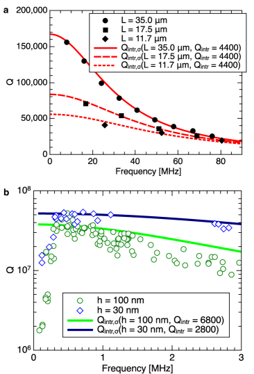
First, examples of values of stoichiometric SiN strings and membranes from literature are discussed with respect to the intrinsic (1) and acoustic radiation loss (3). In Fig. 1a, the intrinsic damping model (1) is applied to values from nanomechanical SiN string resonators Unterreithmeier et al. (2010). The intrinsic model accurately predicts the measured s of several modes of 3 strings with different lengths for a common . Apparently, these strings are narrow enough such that acoustic radiation losses can be neglected and the measured s are clearly limited by intrinsic damping, thereby confirming the conclusions made by the authors of the original paper Unterreithmeier et al. (2010); Faust et al. (2014). The of these strings is relatively large and the influence of the anti-nodal bending becomes significant which can be seen in the steep decrease with higher modes.
In Fig. 1b, the intrinsic model is applied to the measured maximal s of two SiN membrane resonators with a different thickness Chakram et al. (2014). There are two regimes: an initial increase of with frequency (below kHz) and a maximal plateau with a -envelope that slightly decreases with higher frequencies (above kHz). In the former regime, is increasing with frequency and it has repeatedly been shown that s of these lower modes can be increased by minimizing the contact between chip and support Wilson et al. (2009); Wilson (2012); Chakram et al. (2014). Thereby could be lifted up to the maximal plateau, while the magnitude of the plateau remained independent of the mounting condition (see Supplementary Information) Wilson et al. (2009); Wilson (2012). A similar effect has been observed with SiN strings where the free suspension of the chip suppressed the string width-dependent radiation losses (see Supplementary Information) Schmid et al. (2011). It can thus be concluded that radiation loss is responsible for the low s at low frequencies. In the latter plateau regime on the other hand, the observed slight downwards trend is accurately predicted by the intrinsic damping model. With a minute the additional intrinsic loss from the anti-nodal bending of the membrane is low and the maximal plateau remains relatively high also at higher modes. In contrast, the radiation loss model (3) predicts a envelope that is linearly increasing with frequency, which is not the case. The accurate congruence of the experimental data for higher modes with the intrinsic model (1) strongly suggests that the maximal values of higher modes are ultimately limited by intrinsic losses. This evidence is contradicting the conclusions made by the authors of the original paper who argued that radiation loss is the only limiting damping mechanism in both regimes Chakram et al. (2014).
According to (3), is a function of the acoustic mismatch between the resonator and a semi-infinite substrate. At low frequencies however, the resulting wavelengths in the substrate can become larger than the Si chip. In this case the chip-mount (including chip holder, glue, tape, piezo-shaker, etc) has to be considered part of the substrate. Besides the higher radiation loss at lower modes according to (3), the higher sensitivity of the lower frequency s in Fig. 1b to the chip mounting conditions can be explained by a reduced due to the longer wavelengths (an approximate model taking into account the wavelength-dependent is presented in the Supplementary Information). Accordingly, it has recently been demonstrated that of nanomechanical SiN strings deteriorates when the acoustic mismatch is reduced by touching the anchor area with an AFM tip Rieger et al. (2014). A successful way of suppressing radiation losses is to locate the mechanical structure within a well designed phononic bandgap structure. This removes the free frame modes around the membrane and suppresses the probability of phonon tunnelling, i.e. radiation loss Tsaturyan et al. (2014); Yu et al. (2014). The measured maximal s of modes with negligible radiation loss of such a SiN membrane had maximal values that correspond to expected values obtained with similar membranes without the phononic bandgap. This is a strong evidence that s in SiN membranes ultimately can be limited by intrinsic losses if the chip is mounted carefully.
This reduction of for low mode numbers has been observed several times and it is been associated with radiation loss Yu et al. (2012); Wilson et al. (2009); Wilson (2012); Jöckel et al. (2011). Indeed, there are strong indications that the overall mode dependence of Q is best described by a combination of both models. In order to test this we compare low-stress silicon-rich SiN (SR-SiN) (from Norcada) and high-stress stoichiometric SiN (fabricated in-house) membrane data to a combined model that takes into account both, intrinsic and acoustic radiation losses
| (5) |
The membranes were characterized in the frequency domain with a lock-in amplifier (Zurich Instruments HF2PLL) in high vacuum (pressure mbar) at room temperature. The membrane motion was actuated in the linear regime with a piezoelectric shaker and detected with a laser vibrometer (MSA-500 Polytec GmbH).
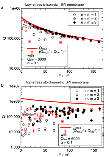
Figs. 2a&b show the measured s for various modes of a SR-SiN and stoichiometric SiN membrane, respectively, with equal dimensions. The combined model (5), based on the exact solution of the radiation loss model Wilson-Rae et al. (2011), is predicting the measured values of both membranes with good accuracy for a single chosen set of parameters and . All the modes in Fig. 2 fulfill the conditions required for the validity of the radiation loss model. The maximal s of the low-stress membrane Fig. 2a are producing an envelope of maximal values which is accurately described by the intrinsic damping model (1) (red line). Hence, the maximal s of the SR-SiN membrane seem to be clearly limited by intrinsic losses. In contrast, the peak s of the high-stress membrane are below the intrinsic loss envelope and they thus seem to be limited by radiation loss. The combined model (5) is shown as red stars. In both membranes, modes with are suppressed strongest by acoustic radiation loss, as predicted by the model, and as it was suggested by Yu et al. (2012). Both Si chips were fixed to the piezoelectric actuator with a double sticky carbon tape. The resonance frequencies are in the MHz-regime which results in wavelengths in the Si that are larger than the Si chip thickness. Hence, the carbon tape and the piezo-shaker become part of the substrate. The lower Young’s modulus of the tape reduces the acoustic mismatch compared to a pure Si substrate, which is reflected in the fit parameter . The lower stress in the SR-SiN membrane results in a better acoustic mismatch and a lower -envelope so that the maximal s are limited by intrinsic losses, which entails s that are less scattered compared to the high-stress membrane. The same effect has been observed with high- and low-stress SiN strings Schmid et al. (2011). Also, the relatively large has the consequence that the damping contribution from the anti-nodal bending becomes significant, which yields the peculiar reduction of with higher mode numbers, as can also be seen e.g. in Fig. 1a. This distinct pattern of intrinsic damping increases the confidence in the correct model application. SR-SiN membranes are thus the optimal structures to investigate the origin of the intrinsic loss, which is presented in the following part.
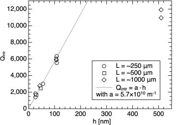
Fig. 3 shows the extracted from the maximal envelope given by intrinsic losses (1) from a set of square SR-SiN membranes with varying thicknesses and lengths . The complete set of measured are plotted in the Supplementary Information. The values increase steadily with membrane thickness , independent of the membrane size . For low the increase is following a linear trend (see linear slope line). In accordance with this trend are the observed thickness dependent s obtained from the intrinsic model in Fig. 1b. A similar linear trend has been observed with Qs of SiN micro cantilevers and was assigned to surface loss , with a slope Yasumura et al. (2000). Hence, the observed linear relationship in Fig. 3 of with is strong evidence of surface loss. For structures with a reduced surface to volume ratio, surface loss will become obsolete and the intrinsic loss will be dominated by volume loss . This can be summarized by the formula
| (6) |
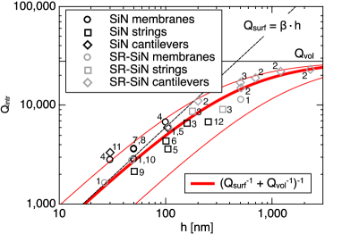
In order to get more data to test the model (6), we extract values for diverse SiN resonators from literature. The values are obtained directly from maximal s of un-stressed cantilevers, and calculated by means of (1) from pre-stressed strings and membranes. All values are listed in Fig. 4 together with the average values from Fig. 3. All values are fitted with (6). Apparently, the trend of all s of all different SiN structures is described accurately by a combination of surface and volume loss. Our membranes had relatively large variations in , , and of %, %, and %, with respect to their nominal values, which propagates to a total uncertainty in the extraction of of %. We took this as our error estimation for all values (thin red lines). From the fit, an average surface loss parameter of m-1 and a volume loss related can be extracted. It seems that all different structure types made from either SR-SiN or stoichiometric SiN are ultimately limited by surface loss. Volume loss starts to significantly contribute in thicker resonators.
The origin of the observed surface loss could be manifold, e.g. surface impurities or surface roughness. The chemical analysis with XPS (X-ray photoelectron spectroscopy) of the surface of two SiN membranes (one commercial stoichiometric LPCVD SiN membrane from Norcada, and one stoichiometric LPCVD SiN membrane fabricated in-house) revealed a high concentration of oxygen and carbon (see Supplementary Information). The same finding was made earlier by Yang et al. Yang et al. (1998) who found oxygen and carbon concentration on the surface of LPCVD SiN of 22 % and 10 %, respectively. It has further been shown that these specific SiN surface impurities remain after cleaning with hydrofluoric acid French et al. (1997). Surface impurities seem to be ubiquitous in LPCVD SiN films. Surface roughness of untreated LPCVD SiN has found to be in the range of 0.3 - 3 nm Yang et al. (1998); Gui et al. (1997). Hence, surface roughness can become a significant fraction of the total SiN thin film thickness.
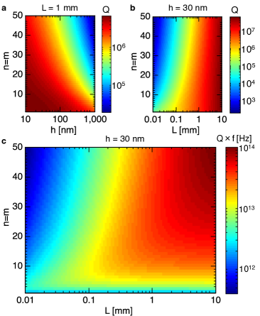
Based on the master-curve for SiN from Fig. 4, it is now possible to predict the maximal obtainable s for harmonic modes of square SiN membranes that are limited by intrinsic loss. From Fig. 5a it becomes evident that the thickness does not significantly influence of thin membranes at low mode numbers, an effect that has been observed experimentally Adiga et al. (2012). This is a direct effect of the that decreases with thickness and hence counteracts the -enhancing effect of a small in (1). Thinner membranes only result in higher s at higher modes. For Fig. 5b the thickness is fixed to 30 nm. It is not surprising that larger membranes result in higher s. For large membranes, is stable over many modes, which again can be seen in Fig. 1b. But starts to deteriorate with mode numbers when becomes large, an effect that can be seen with short SiN strings in Fig. 1a. In quantum cavity optomechanics a figure of merit is the product. It is a direct measure for the decoupling of the mechanical resonator from the thermal environmental bath with temperature . With , Hz is the minimum requirement for room-temperature quantum optomechanics Aspelmeyer et al. . In that case the thermal decoherence can be neglected over one mechanical period of vibration . The maximal product obtainable with a SiN membrane at room temperature is shown in Fig. 5c. It seems that the limit can not be overcome in the fundamental mode independent of membrane size, confirming the experimental findings from Wilson et al. Wilson et al. (2009). For SiN string resonators, the maximal values for low mode numbers are equal to the ones displayed in Fig. 5a&b, but the product values have to be divided by . It has been shown that intrinsic damping is reduced at cryogenic temperatures which means that all predicted values in Fig. 5 will increase accordingly Tsaturyan et al. (2014); Faust et al. (2014); Southworth et al. (2009).
In conclusion, in pre-stressed SiN micro- and nanomechanical resonators is limited by a combination of intrinsic and acoustic radiation loss. In membranes, both respective s scale linearly with the dimensions (). Hence, the limiting damping mechanism is mainly determined by the acoustic mismatch of the membrane to the substrate (). In high-stress SiN membranes, is reduced and the maximal intrinsic loss -limit is increased, hence the resulting values are strongly mode dependent and are scattered due to radiation loss. The maximal s can become limited by intrinsic loss by maximizing the acoustic mismatch e.g. by mounting the chip freely or with a phononic bandgap structure. In contrast, low-stress SiN membranes have a higher acoustic mismatch to the substrate and the maximal intrinsic -limit is lower. Hence, the resulting s of higher mode numbers () reach an upper envelope that is limited by intrinsic losses, while lower mode numbers () can be limited by radiation loss. Generally, radiation loss is minimal for symmetric modes (). In SiN strings, radiation loss scales inversely with width and narrow strings can become limited by intrinsic loss.
The intrinsic quality factors of thin low-stress SiN membranes scale linearly with the membrane thickness, which is strong evidence of surface loss. The same linear scaling of has been confirmed by independent SiN data taken from literature (cantilevers, strings and membranes) which is evidence that surface loss is the ubiquitous limiting damping mechanism in thin arbitrary SiN resonators with a scaling factor m-1. For thin pre-stressed resonators that are limited by intrinsic loss, the thickness dependent surface loss is counteracting the -enhancement at low mode numbers and can only significantly be increased with the size . Finally, it seems that Hz required for quantum cavity optomechanics at room temperature can not be reached with the fundamental mode, independent of resonator length.
Acknowledgements.
The authors would like to acknowledge A. Boisen for her support, and the staff in DTU-Danchip for help in the fabrication of the membranes. The authors further thank B. Amato for the help in the laboratory, A. Schliesser for his valuable input, and I. Wilson-Rae for the generous support with the radiation loss model. This research is supported by the Villum Foundation’s Young Investigator Program (Project No. VKR023125) and the Swiss National Science Foundation (PP00P2 144695).References
- Verbridge et al. (2006) S. S. Verbridge, J. M. Parpia, R. B. Reichenbach, L. M. Bellan, and H. G. Craighead, Journal of Applied Physics 99, 124304 (2006).
- Zwickl et al. (2008) B. M. Zwickl, W. E. Shanks, A. M. Jayich, C. Yang, B. Jayich, J. D. Thompson, and J. G. E. Harris, Applied Physics Letters 92, 103125 (2008).
- Thompson et al. (2008) J. D. Thompson, B. M. Zwickl, A. M. Jayich, F. Marquardt, S. M. Girvin, and J. G. E. Harris, Nature 452, 72 (2008).
- Gavartin et al. (2012) E. Gavartin, P. Verlot, and T. J. Kippenberg, Nature Nanotechnology 7, 509 (2012).
- Purdy et al. (2013) T. P. Purdy, R. W. Peterson, and C. A. Regal, Science 339, 801 (2013).
- Brawley et al. (2014) G. A. Brawley, M. R. Vanner, P. E. Larsen, S. Schmid, A. Boisen, and W. P. Bowen, (2014), arXiv:1404.5746 .
- Wilson et al. (2009) D. J. Wilson, C. A. Regal, S. B. Papp, and H. J. Kimble, Phys. Rev. Lett. 103, 207204 (2009).
- Faust et al. (2012) T. Faust, P. Krenn, S. Manus, J. Kotthaus, and E. Weig, Nature Communications 3, 728 (2012).
- Anetsberger et al. (2010) G. Anetsberger, E. Gavartin, O. Arcizet, Q. P. Unterreithmeier, E. M. Weig, M. L. Gorodetsky, J. P. Kotthaus, and T. J. Kippenberg, Physical Review A 82, 061804 (2010).
- Hammerer et al. (2009) K. Hammerer, M. Wallquist, C. Genes, M. Ludwig, F. Marquardt, P. Treutlein, P. Zoller, J. Ye, and H. Kimble, Physical Review Letters 103, 063005 (2009).
- Camerer et al. (2011) S. Camerer, M. Korppi, A. Jöckel, D. Hunger, T. W. Hänsch, and P. Treutlein, Physical Review Letters 107, 223001 (2011).
- Andrews et al. (2014) R. W. Andrews, R. W. Peterson, T. P. Purdy, K. Cicak, R. W. Simmonds, C. A. Regal, and K. W. Lehnert, Nature Physics 10, 321 (2014).
- Bagci et al. (2014) T. Bagci, A. Simonsen, S. Schmid, L. G. Villanueva, E. Zeuthen, J. Appel, J. M. Taylor, A. Sø rensen, K. Usami, A. Schliesser, and E. S. Polzik, Nature 507, 81 (2014).
- Hanay et al. (2012) M. S. Hanay, S. Kelber, A. K. Naik, D. Chi, S. Hentz, E. C. Bullard, E. Colinet, L. Duraffourg, and M. L. Roukes, Nature Nanotechnology 7, 602 (2012).
- Barton et al. (2010) R. A. Barton, B. Ilic, S. S. Verbridge, B. R. Cipriany, J. M. Parpia, and H. G. Craighead, Nano Letters 10, 2058 (2010).
- Yamada et al. (2013) S. Yamada, S. Schmid, T. Larsen, O. Hansen, and A. Boisen, Analytical Chemistry 85, 10531 (2013).
- Schmid et al. (2013) S. Schmid, M. Kurek, J. Q. Adolphsen, and A. Boisen, Scientific Reports 3, 1288 (2013).
- Larsen et al. (2013) T. Larsen, S. Schmid, L. G. Villanueva, and A. Boisen, ACS Nano 7, 6188 (2013).
- Schmid et al. (2014) S. Schmid, K. Wu, P. E. Larsen, T. Rindzevicius, and A. Boisen, Nano Letters 14, 2318 (2014).
- Schmid et al. (2011) S. Schmid, K. D. Jensen, K. H. Nielsen, and A. Boisen, Physical Review B 84, 165307 (2011).
- Unterreithmeier et al. (2010) Q. P. Unterreithmeier, T. Faust, and J. P. Kotthaus, Physical Review Letters 105, 27205 (2010).
- Adiga et al. (2012) V. P. Adiga, B. Ilic, R. A. Barton, I. Wilson-Rae, H. G. Craighead, and J. M. Parpia, Journal of Applied Physics 112, 064323 (2012).
- Chakram et al. (2014) S. Chakram, Y. S. Patil, L. Chang, and M. Vengalattore, Physical Review Letters 112, 127201 (2014).
- Yu et al. (2012) P.-L. Yu, T. Purdy, and C. Regal, Physical Review Letters 108, 1 (2012).
- Gonzfilez and Saulson (1994) G. I. Gonzfilez and P. R. Saulson, Journal of the Acoustical Society of America 96, 207 (1994).
- Boisen et al. (2011) A. Boisen, S. Dohn, S. S. Keller, S. Schmid, and M. Tenje, Reports on Progress in Physics 74, 036101 (2011).
- Cagnoli et al. (2000) G. Cagnoli, J. Hough, D. Debra, M. M. Fejer, E. Gustafson, S. Rowan, and V. Mitrofanov, Physics Letters 272, 39 (2000).
- Wilson-Rae (2008) I. Wilson-Rae, Physical Review B 77, 245418 (2008).
- Wilson-Rae et al. (2011) I. Wilson-Rae, R. A. Barton, S. S. Verbridge, D. R. Southworth, B. Ilic, H. G. Craighead, and J. M. Parpia, Physical Review Letters 106, 47205 (2011).
- (30) The asymptotic limit of the radiation loss model Wilson-Rae et al. (2011) was derived and generously provided by I. Wilson-Rae .
- Cross and Lifshitz (2001) M. C. Cross and R. Lifshitz, Physical Review B 64, 85324 (2001).
- Faust et al. (2014) T. Faust, J. Rieger, M. J. Seitner, J. P. Kotthaus, and E. M. Weig, Physical Review B 89, 100102 (2014).
- Wilson (2012) D. J. Wilson, Cavity Optomechanics with High-Stress Silicon Nitride Films, Ph.D. thesis, California Institute of Technology (2012).
- Rieger et al. (2014) J. Rieger, A. Isacsson, M. J. Seitner, J. P. Kotthaus, and E. M. Weig, Nature Communications 5, 1 (2014).
- Tsaturyan et al. (2014) Y. Tsaturyan, A. Barg, A. Simonsen, L. G. Villanueva, S. Schmid, A. Schliesser, and E. S. Polzik, Optics Express 22, 6810 (2014).
- Yu et al. (2014) P.-L. Yu, K. Cicak, N. S. Kampel, Y. Tsaturyan, T. P. Purdy, R. W. Simmonds, and C. A. Regal, Applied Physics Letters 104, 023510 (2014).
- Jöckel et al. (2011) A. Jöckel, M. T. Rakher, M. Korppi, S. Camerer, D. Hunger, M. Mader, and P. Treutlein, Applied Physics Letters 99, 143109 (2011).
- Yasumura et al. (2000) K. Y. Yasumura, T. D. Stowe, E. M. Chow, T. Pfafman, T. W. Kenny, B. C. Stipe, and D. Rugar, Journal of Microelectromechanical Systems 9, 117 (2000).
- Verbridge et al. (2008) S. S. Verbridge, H. G. Craighead, and J. M. Parpia, Applied Physics Letters 92, 013112 (2008).
- Southworth et al. (2009) D. R. Southworth, R. A. Barton, S. S. Verbridge, B. Ilic, A. D. Fefferman, H. G. Craighead, and J. M. Parpia, Physical review letters 102, 225503 (2009).
- Suhel et al. (2012) A. Suhel, B. D. Hauer, T. S. Biswas, K. S. D. Beach, and J. P. Davis, Applied Physics Letters 100, 173111 (2012).
- Yang et al. (1998) G.-R. Yang, Y.-P. Zhao, Y. Hu, T. Paul Chow, and R. J. Gutmann, Thin Solid Films 333, 219 (1998).
- French et al. (1997) P. J. French, P. M. Sarro, R. Malle, E. J. M. Fakkeldij, and R. F. Wolffenbuttel, Sensors and Actuators A: Physical 58, 149 (1997).
- Gui et al. (1997) C. Gui, H. Albers, J. G. E. Gardeniers, M. Elwenspoek, and P. V. Lambeck, Microsystem Technologies 3, 122 (1997).
- (45) M. Aspelmeyer, T. J. Kippenberg, and F. Marquardt, arXiv:1303.0733 .