Tunable beam displacer
Abstract
We report the implementation of a tunable beam displacer, composed of a polarizing beam splitter (PBS) and two mirrors, that divides an initially polarized beam into two parallel beams whose separation can be continuously tuned. The two output beams are linearly polarized with either vertical or horizontal polarization and no optical path difference is introduced between them. The wavelength dependence of the device as well as the maximum separation between the beams achievable is limited mainly by the PBS characteristics.
pacs:
42.79.Fm, 07.60.-jA beam displacer (BD) is a device that splits an input polarized beam into two spatially separated beams that propagate parallel with orthogonal polarizations. Commercially available BD are made of birefringent materials like Calcite crystal, Barium Borate () crystal, Rutile crystal or Yttrium Vanadate () among others BeamDisplacers . In these devices, due to the intrinsic birefringence of the material, the propagation direction of the ordinary polarized beam is unchanged whereas the extraordinary component deviates inside the crystal Fowles1975 . The resulting beam separation is specific for each material and its maximum value depends on the crystal length, which is typically on the order of centimeters, limiting the maximum separation achievable to a few millimeters. Apart from a spatial separation, typical BD also introduce a temporal delay between the beams with orthogonal polarization, which may be detrimental in some applications.
Adding tunability to the spatial separation introduced by a BD is desired in applications where one needs to maintain the direction of propagation and control the spatial overlap between two beams Susa2012a ; Craven2012 . To the best of our knowledge, tunable beam displacers (TBD) are implemented by either using a tweaker plate (for instance, Thorlabs - XYT-A), or thin film polarizers (for instance II-VI UK LTD - ZnSe TFP). A proposal to add tunability to a BD was presented by Feldman et al. Feldman2006 , where an adjustable Wollaston prism is implemented. In this work, we present an implementation of a TBD that allows to generate a considerably large and controllable beam separation. Our TBD is based on the device described by Feldman et al. Feldman2006 with the difference that our device does not use quarter waveplates that limit the spatial quality of the beam and the wavelength range of operation.
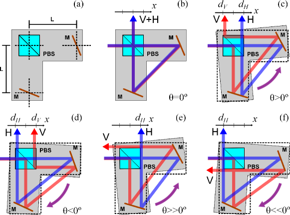
The geometry of our implementation of a TBD is shown in Fig. 1 (a). Two mirrors are positioned equidistant at a distance from a polarizing beam splitter (PBS) and fixed to a L-shaped plaque that is free to rotate an angle with respect to the PBS center. When , as shown in Fig. 1 (b), the two output beams with orthogonal polarizations propagate collinearly superimposed on each other. On the other hand, when the platform is rotated, the beams with orthogonal polarizations no longer overlap in space and emerge at the output separated by a distance that depends on the angle , , the size of the PBS and the beam diameter. In Fig. 1 (c), and correspond to the beam separations for the horizontal and vertical output components, measured with respect to the central position of the beams, when the platform is not rotated. When , anti-clockwise rotation as shown in Fig. 1 (c), the beam with horizontal polarization is separated by a distance with respect to the reference position, whereas for the beam with vertical position . In contrast, when the platform is rotated in the opposite direction, , clockwise rotation as shown in Fig. 1 (d), the polarization of the output beams are reversed and thus the sign of and . Figs. 1 (e) and 1 (f) illustrate the limiting cases where the angle is such that the beam with vertical polarization is no longer reflected by the PBS and thus it is not collinear to its output pair with horizontal polarization.
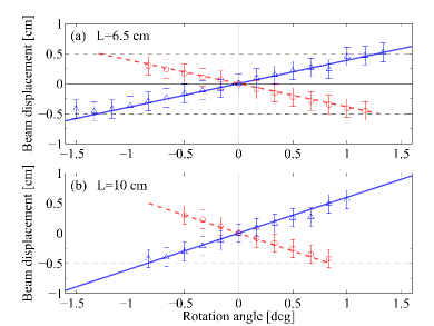
It would be desirable to obtain an analytical expression that would relate the beam displacement with , , the size of the PBS and the input beam diameter. Even though, the geometry of the TBD is simple, such an analytical expression for the displacement is not straightforward because the relationship between the angle and the orientation of the mirrors is not easily manageable. Fortunately, since the device can be modeled only by consecutive reflections on the mirrors and the PBS (refractions on the PBS can be neglected due to the fact that all the beams impinging and emerging from the PBS are perpendicular to its surface), a numerical model is at hand. We developed a ray tracing model in which reflections are calculated according to the law of reflection considering the position where a beam hits the mirror. In addition, the PBS is modeled as a two sided mirror in which the vertical polarization reflects two times and the horizontal component is only transmitted. The solid and dashed lines in Fig. 2 show the beam displacements for the output beams with horizontal (solid) and vertical (dashed) polarizations obtained with our ray tracing model, as a function of . The two figures correspond to different values of .
In all cases, it is observed a central region where the separation between the beams varies linearly with the angle . Beyond this region, our model is not valid: presents a discontinuity that corresponds to values of in which the vertical component is no longer reflected on the PBS and thus the output beams with vertical and horizontal polarizations do not propagate collinearly [see Figs. 1 (e) and 1 (f)]. The maximum separation, shown as horizontal dashed lines in Figs. 2 (a) and 2 (b), is limited by the PBS size. As increases, the sensitivity of the tunability of the device improves, which is revealed by noticing that for both polarizations, the slope of the beam displacement in Fig. 2 (b) is steeper than the corresponding slope in Fig. 2 (a).
Our ray tracing model also reveals a useful feature of the TBD: the temporal delay between the orthogonally polarized beams, arising from the optical path difference, is zero. At first sight, since the beams impinge on different regions of the mirrors and PBS, one expects that they travel a different optical path; however, our ray tracing model reveals that this is not the case. Interestingly, this feature is valid for any value of , and adds a unique feature to our TBD with respect to other beam displacers.
To corroborate our theoretical model, we implemented an experimental setup corresponding to Fig. 1 (a). As input beam we used a He-Ne laser with a Gaussian beam profile (beam diameter: ) polarized at by using a polarizer. This beam impinges on a PBS, antireflection coated for , and the two orthogonal polarization components separated by the PBS are then reflected by aluminium mirrors (diameter ) placed on the L-shaped platform that is allowed to rotate at specific values of by using a manual rotational stage. At the output, the beam position is recorded by a camera and the centroid of the different images define and , accordingly.
For initial alignment, is set to zero and the angle for each mirror is set such that each beam reflected on the mirrors propagates towards the PBS center and only one beam is seen in the camera. The centroid of this image sets the reference to measure and [Fig. 1 (b)]. The experimental results for and , in the interval , are depicted in Fig. 2 (a) for and in Fig. 2 (b) for . The experimental results and the predictions from the ray tracing model are in excellent agreement in the region where two parallel beams with orthogonal polarizations are obtained at the output.
In conclusion, we have presented a tunable beam displacer, composed of a PBS, two mirrors and a rotating platform, where the mirrors are fixed, that allows to transform a polarized beam into two parallel beams spatially separated by a tunable distance. The wavelength dependence of the device and the range of tunability of the separation are only limited by the characteristics of PBS and mirrors. In particular, we obtained experimentally beam displacements up to limited only by the PBS size. An additional interesting characteristic of the TBD we proposed here is the absence of a temporal delay between the horizontal and vertical output beams. This feature is relevant for applications where temporal compensation is not available.
We acknowledge support from the Spanish government projects FIS2010-14831 and Severo Ochoa programs, and from Fundació Privada Cellex, Barcelona. LJSS and AV acknowledges support from Facultad de Ciencias, Universidad de los Andes Bogotá, Colombia.
References
- (1) Some of the most popular manufacturers of beam displacers are Thorlabs, Altechna, Precision micro-optics and EKSMA.
- (2) G. R. Fowles, “Introduction to modern optics”, Dover, (1975).
- (3) Y. Susa, Y. Shikano, and A. Hosoya, Phys. Rev. A. 85, 052110 (2012).
- (4) J. Craven-Jones, M. W. Kudenov, E. L. Dereniak, Opt. Eng. 51, 013002 (2012).
- (5) M. Feldman, A. El-Amawy, A. Srivastava, and R. Vaidyanathan, Rev. Sci. Instrum. 77, 066109 (2006).