Intermittency in an Optomechanical Cavity Near a Subcritical Hopf Bifurcation
Abstract
We experimentally study an optomechanical cavity consisting of an oscillating mechanical resonator embedded in a superconducting microwave transmission line cavity. Tunable optomechanical coupling between the mechanical resonator and the microwave cavity is introduced by positioning a niobium-coated single mode optical fiber above the mechanical resonator. The capacitance between the mechanical resonator and the coated fiber gives rise to optomechanical coupling, which can be controlled by varying the fiber-resonator distance. We study radiation pressure induced self-excited oscillations as a function of microwave driving parameters (frequency and power). Intermittency between limit cycle and steady state behaviors is observed with blue-detuned driving frequency. The experimental results are accounted for by a model that takes into account the Duffing-like nonlinearity of the microwave cavity. A stability analysis reveals a subcritical Hopf bifurcation near the region where intermittency is observed.
pacs:
46.40.- f, 05.45.- a, 65.40.De, 62.40.+ iThe field of cavity optomechanics Braginsky and Manukin (1967); Marquardt and Girvin (2009); Girvin (2009); Kippenberg and Vahala (2008) deals with a family of systems, each is composed of two coupled elements. The first one is a mechanical resonator, commonly having low damping rate, and the second one is an electromagnetic cavity, which is typically externally driven. Both radiation pressure Corbitt et al. (2007); Gigan et al. (2006); Arcizet et al. (2006); Schliesser et al. (2006); Thompson et al. (2008); Nichols and Hull (1901); Carmon et al. (2005a); Jayich et al. (2008); Schliesser et al. (2008) and bolometric force Metzger and K.Karrai (2004); Jourdan et al. (2008); Metzger et al. (2008); Marino and Marin (2010); Restrepo et al. (2011); Liberato et al. (2010); Marquardt et al. (2006); Paternostro et al. (2006); Aubin et al. (2004); Marquardt et al. (2006); Zaitsev et al. (2011b); Zaitsev et al. (2012) can give rise to the coupling between the mechanical resonator and the cavity. In recent years a variety of cavity optomechanical systems have been constructed and studied Hane and Suzuki (1996); Kippenberg and Vahala (2008); Corbitt and Mavalvala (2004); Corbitt et al. (2007); Metzger and K.Karrai (2004); Gigan et al. (2006); Arcizet et al. (2006); Kleckner and Bouwmeester (2006); I. Favero et al. (2007); Regal et al. (2008); Carmon et al. (2005b); Schliesser et al. (2006); Thompson et al. (2008); Chan et al. (2011); Teufel et al. (2011a, b); O Connell et al. (2010); Gr blacher et al. (2013), and phenomena such as mode cooling Teufel et al. (2011a, b); Gröblacher et al. (2009); Schliesser et al. (2009); Chan et al. (2011), self-excited oscillations Hane and Suzuki (1996); Kim and Lee (2002); Aubin et al. (2004); Carmon et al. (2005b); Marquardt et al. (2006); Corbitt et al. (2006); Carmon and Vahala (2007); Metzger et al. (2008); Regal et al. (2008) and optically induced transparency Weis et al. (2010); Karuza et al. (2013); Safavi-Naeini et al. (2011); Ojanen and Borkje (2014) have been investigated. In addition to applications in metrology Braginsky and Khalili (1995); Clerk et al. (2010) and photonics Hossein-Zadeh and Vahala (2010); Bagheri et al. (2011); Zhou et al. (2013), the appeal of optomechanics lies in the potential for observation of macroscopic quantum behavior in mechanical systems Teufel et al. (2011b); O Connell et al. (2010); Kimble et al. (2001); Genes et al. (2008); Teufel et al. (2010); Rodrigues and Armour (2010); Qian et al. (2011); Palomaki et al. (2013); He and Reid (2013); Pikovski et al. (2012); Poot and van der Zant (2012); Meaney et al. (2011); Walter et al. (2013); Lörch et al. (2014); Galland et al. (2013); Kiesewetter et al. (2013); Bahrami et al. (2014); Farace et al. (2013); Xu et al. (2013); Weinstein et al. (2014); Xu et al. (2014). While much experimental and theoretical progress has been made in reaching the ground state and observing the linear dynamics of mechanical objects, it is becoming appreciated that nonlinearity allows the creation of non-classical mechanical states L rch et al. (2014) and can be exploited for improving the efficiency of optomechanical cooling Nation et al. (2008). It is therefore important to study and shed light on the nonlinear dynamics of these devices.

In this work we experimentally study self-excited oscillations in an optomechanical cavity operating in the microwave band. We introduce a novel method for achieving strong and tunable optomechanical coupling, which is based on positioning a metallically coated optical fiber near the mechanical resonator. The microwave cavity, which is made of a superconducting aluminum microstrip, exhibits Kerr type nonlinearity Dahm and Scalapino (1997); Suchoi et al. (2010); Yurke and Buks (2006); B rkje et al. (2013), which significantly affects the dynamics of the entire optomechanical system Nation et al. (2008). We study the dependence of the self-excited oscillations on the driving parameters of the cavity and found that a good agreement with theory can be obtained provided that cavity nonlinearity is taken into account Nation et al. (2008). We experimentally find that in a certain region of drive parameters the system exhibits random jumps between a limit-cycle (i.e. self-excited oscillations) and a steady-state. A theoretical stability analysis reveals that this observed intermittency behavior occurs near a subcritical Larson and Horsdal (2011); Holmes et al. (2012); Blocher et al. (2013); Meaney et al. (2011) Hopf bifurcation Walter et al. (2013); Lörch et al. (2014).
The experimental setup is schematically depicted in Fig. 1. Magnetron DC sputtering is employed for coating a high resistivity silicon wafer with aluminum. The aluminum layer is annealed in situ at 400∘C for minutes to reduce internal stress in the layer Jaecklin et al. (1994). A standard photo-lithography process is used to pattern the microwave microstrip cavity. At the open end of the microstrip a 100nm thick SiN membrane is fabricated Zaitsev et al. (2011b). The mechanical resonator is made by releasing a m2 trampoline supported by four beams using electron cyclotron resonance (ECR) dry etch. At the other end the cavity is weakly coupled to a feedline, which guides both the injected and reflected microwave signals. The results presented here are obtained with a device having a fundamental cavity resonance frequency GHz, cavity linear damping rate 420kHz, fundamental mechanical resonance frequency 12.1kHz and mechanical Q-factor .
As can be seen in Fig. 1, a single mode optical fiber coated with niobium is placed above the suspended trampoline. In the presence of the coated fiber two optomechanical cavities are formed, one in the microwave band and the other in the optical band Zaitsev et al. (2011a). The fact that both optomechanical cavities share the same mechanical resonator can be exploited for conversion between microwave and optical photons Andrews et al. (2013); Jiang et al. (2014); Fong et al. (2014); Clader (2014); Bochmann et al. (2013). However, in the present work we employ the optical cavity and the optical setup seen in Fig. 1 only for fiber positioning and for characterization of the mechanical resonator at high temperatures, whereas all low temperature measurements that are discussed below are done in the microwave band only.
We employ a telecom single mode optical fiber having a fiber Bragg grating (FBG) mirror Zaitsev et al. (2011a) and a focusing lens, made by melting the fiber tip. Magnetron DC sputtering is used for coating the fiber with niobium. To allow optical transmission, we etch the niobium coating using focused ion beam (FIB), exposing thus the core of the fiber at the tip. A cryogenic piezoelectric 3-axis positioning system having sub-nanometer resolution is employed for manipulating the position of the optical fiber.
Optomechanical coupling between the microwave cavity and the mechanical resonator is introduced due to the capacitance between the coated fiber and the suspended trampoline, which is given by approximately Russel (1922), where =350 m is the radius of curvature of the melted fiber tip, is the fiber-trampoline distance and is the vacuum permittivity. A hole of diameter 2.4mm and depth 2.7mm is drilled in the sample package, which is made of copper, above the trampoline in order to allow inserting the optical fiber, which has an outer diameter of 125 m. When the fiber is centered inside the hole, the fiber-package coaxial capacitance is given by Pozar (1998). When radiation loss is disregarded, the effect of the coated fiber on microwave cavity modes can be accounted for by assuming that a termination having purely imaginary impedance given by , where , has been introduced between the microstrip end and ground. The frequencies of the cavity modes can be found by solving Pozar (1998), where the propagation constant is related to by , is the propagation velocity in the microstrip, is the length of the microstrip, and 48 is its characteristic impedance. Comparison between the measured and calculated values of the cavity fundamental mode frequency is seen in panel (d) of Fig. 1. The dependence of on fiber-trampoline distance allows the extraction of optomechanical coupling coefficient , which is found to be given by =55MHz m-1 for our chosen operating point, where m is the mechanical zero point amplitude, and where kg is the effective mass of the mechanical mode.
The microwave cavity is excited by injecting a monochromatic pump signal having frequency and amplitude into the feedline and monitoring the off-reflected signal using either a spectrum analyzer or a diode connected to an oscilloscope [see panel (a) of Fig. 1]. The amplitude is related to the pump power by , where represents the contribution to the total cavity linear damping rate due to cavity-feedline coupling Yurke and Buks (2006). In the absence of any optomechanical coupling (i.e. when the fiber is positioned far from the trampoline) the cavity reflectivity exhibits bistability in a certain region in the plane of pump parameters (frequency and amplitude ) originates by cavity Kerr nonlinearity. The border line of this region contains a cusp point, which is also known as the onset of bistability point Yurke and Buks (2006). The values of pump frequency and pump amplitude at that critical point are labeled by and , respectively. In what follows we employ normalized and dimensionless parameters for the pump detuning and for the pump amplitude .
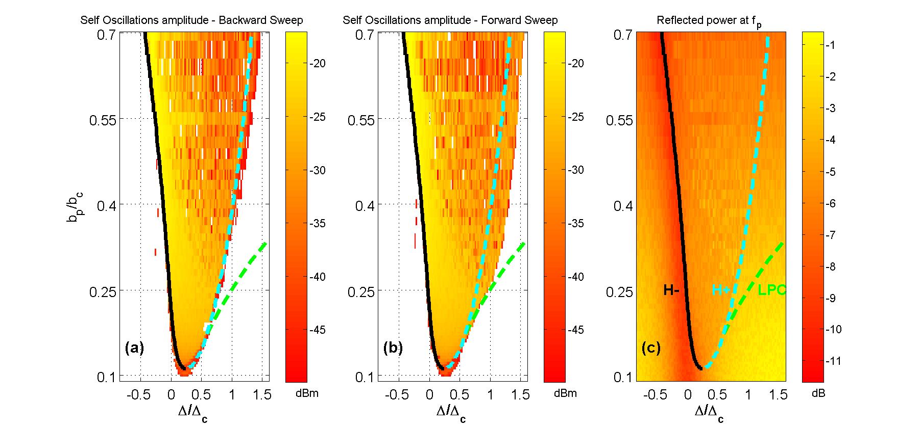
Panels (a) and (b) of Fig. 2 show the reflected microwave power, which is measured using a spectrum analyzer, at frequency , where is the mechanical resonance frequency, for both forward and backward sweeps of the pump frequency . A strong peak is found at frequency [as well as at other harmonics where is integer, as can be seen in panel (a) of Fig. 3] in a certain region in the the plane of normalized pump parameters and , inside which self-excited oscillations occur. The height of the peak at frequency is plotted in panels (a) and (b) of Fig. 2. The results obtained with backward sweep [panel (a)] differ from those obtained with forward sweep [panel(b)], which indicates that the cavity response is hysteretic due to bistability. Panel (c) depicts the reflected power at .
Cavity nonlinearity plays a crucial role in the observed behavior of the system. We employ the theoretical modeling of Refs. Nation et al. (2008); Buks (2012) to account for cavity Kerr nonlinearity Tholen et al. (2007); Dahm and Scalapino (1997). The equations of motion in the rotating frame of the cavity for the annihilation operators and of the cavity and mechanical resonator, respectively, are found to be given by and where
| (1) |
| (2) |
and where is the effective cavity detuning, is the optomechanical coupling coefficient, is the cavity Kerr nonlinearity constant, () is the cavity (mechanical) angular resonance frequency, () is the cavity (mechanical) linear damping rate, is the cavity nonlinear damping rate, is the cavity number operator and is the pump amplitude. The terms and represent white noise having (frequency independent) power spectrum given by and , respectively, where , , is Boltzmann’s constant and is the temperature.

The stability map of the system is obtained using the numerical continuation package MATCONT (URL: http://www.matcont.ugent.be/). First, a steady state solution (i.e. solution to ) is found for each operating point in the plane of pump parameters. Note that for the region seen in Fig. 2 the steady state is unique (since ). Then MATCONT is employed to identify bifurcations. The solid black, dotted cyan and dotted green lines in Fig. 2 represent, respectively, supercritical Hopf (labeled as ), subcritical Hopf (labeled as ) and limit point of cycle (LPC) bifurcations. In the numerical investigation noise is disregarded and the operators and are treated as c-numbers. The cavity parameters that are used for the numerical calculation are listed in the caption of Fig. 2. The bifurcation lines divide the region in the plane of pump parameters seen in Fig. 2 into three zones. In the zone between the and bifurcations only a single limit-cycle is found to be locally stable (though the existence of other locally stable solutions cannot be ruled out), in the zone between the and LPC bifurcations bistability of a limit-cycle and a steady state occurs, whereas elsewhere only a unique steady state is found.
Intermittency, i.e. random jumps between the limit-cycle and the steady state, is experimentally observed for . Fig. 3 shows frequency and time domain measurements taken with normalized pump amplitude given by . Panel (a) shows the frequency decomposition of the reflected signal as the pump frequency is scanned and the white line shows the reflected power at frequency . Regular self-excited oscillations in the time domain can be seen in panel (c) for normalized detuning . At larger detuning (in the bistable zone), however, random transitions between the limit cycle and the steady state occur, as can be seen in panel (b). The limit cycle and the steady state in the complex projection plane of phase space are plotted in panel (d). Note that the dynamics near the steady state remains relatively slow even when it becomes locally unstable (i.e. in the zone between the H- and H+ bifurcations). Consequently, in the presence of noise even a locally unstable steady state can give rise to intermittency-like behavior provided that it is sufficiently close to the limit cycle. Indeed, intermittency is experimentally observed on both sides of the H+ bifurcation.
In summary, we find that a subcritical Hopf bifurcation is the underlying mechanism that is responsible for the experimentally observed intermittency. While the current study is focused on the classical dynamics, future study will explore the possibility of exploiting dynamical bistability for the creation of macroscopic non-classical states of the optomechanical system Armour and Rodrigues (2012).
This work was supported by the Israel Science Foundation, the bi-national science foundation, the Deborah Foundation, the Israel Ministry of Science, the Russell Berrie Nanotechnology Institute, the European STREP QNEMS Project and MAFAT. The authors thank Ya’akov Schneider for helping in sample fabrication.
References
- Andrews et al. (2013) Andrews, R., R. Peterson, T. Purdy, K. Cicak, R. Simmonds, C. Regal, and K. Lehnert, 2013, arXiv preprint arXiv:1310.5276 .
- Arcizet et al. (2006) Arcizet, O., P.-F. Cohadon, T. Briant, M. Pinard, and A. Heidmann, 2006, Nature 444, 71.
- Armour and Rodrigues (2012) Armour, A. D., and D. A. Rodrigues, 2012, Comptes Rendus Physique 13(5), 440.
- Aubin et al. (2004) Aubin, K., M. Zalalutdinov, T. Alan, R. Reichenbach, R. Rand, A. Zehnder, J. Parpia, and H. Craighead, 2004, J. MEMS 13, 1018.
- Bagheri et al. (2011) Bagheri, M., M. Poot, M. Li, W. P. H. Pernice, and H. X. Tang, 2011, Nature Nanotechnology 6, 726.
- Bahrami et al. (2014) Bahrami, M., M. Paternostro, A. Bassi, and H. Ulbricht, 2014, arXiv:1402.5421 .
- Blocher et al. (2013) Blocher, D., R. H. Rand, and A. T. Zehnder, 2013, International Journal of Non-Linear Mechanics 52, 119.
- Bochmann et al. (2013) Bochmann, J., A. Vainsencher, D. D. Awschalom, and A. N. Cleland, 2013, Nature Physics 103, 122602.
- Braginsky and Khalili (1995) Braginsky, V., and F. Khalili, 1995, Quantum Measurement (Cambridge University Press, Cambridge).
- Braginsky and Manukin (1967) Braginsky, V., and A. Manukin, 1967, Soviet Physics JETP 25, 653.
- B rkje et al. (2013) B rkje, K., A. Nunnenkamp, J. D. Teufel, and S. M. Girvin, 2013, Phys. Rev. Lett. 111, 053603, URL http://link.aps.org/doi/10.1103/PhysRevLett.111.053603.
- Buks (2012) Buks, E., 2012, C. R. Physique 13, 454.
- Carmon et al. (2005a) Carmon, T., H. Rokhsari, L. Yang, T. J. Kippenberg, and K. J. Vahala, 2005a, Phys. Rev. Lett. 94, 223902.
- Carmon et al. (2005b) Carmon, T., H. Rokhsari, L. Yang, T. J. Kippenberg, and K. J. Vahala, 2005b, Phys. Rev. Lett. 94, 223902.
- Carmon and Vahala (2007) Carmon, T., and K. J. Vahala, 2007, Phys. Rev. Lett. 98, 123901.
- Chan et al. (2011) Chan, J., T. Alegre, A. Safavi-Naeini, J. Hill, A. Krause, S. Gröblacher, M. Aspelmeyer, and O. Painter, 2011, Nature 478(7367), 89.
- Clader (2014) Clader, B., 2014, arXiv:1403.7056 .
- Clerk et al. (2010) Clerk, A., M. Devoret, S. Girvin, F. Marquardt, and R. Schoelkopf, 2010, Reviews of Modern Physics 82(2), 1155.
- Corbitt et al. (2007) Corbitt, T., Y. Chen, E. Innerhofer, H. Müller-Ebhardt, D. Ottaway, H. Rehbein, D. Sigg, S. Whitcomb, C. Wipf, and N. Mavalvala, 2007, Physical review letters 98(15), 150802.
- Corbitt and Mavalvala (2004) Corbitt, T., and N. Mavalvala, 2004, Journal of Optics B: Quantum and Semiclassical Optics 6(8), S675.
- Corbitt et al. (2006) Corbitt, T., D. Ottaway, E. Innerhofer, J. Pelc, and N. Mavalvala, 2006, Phys. Rev. A 74, 21802.
- Dahm and Scalapino (1997) Dahm, T., and D. J. Scalapino, 1997, Journal of Applied Physics 81(4), 2002, URL http://dx.doi.org/10.1063/1.364056.
- Farace et al. (2013) Farace, A., F. Ciccarello, R. Fazio, and V. Giovannetti, 2013, arXiv preprint arXiv:1306.1142 .
- Fong et al. (2014) Fong, K. Y., L. Fan, L. Jiang, X. Han, and H. X. Tang, 2014, arXiv:1404.3427 .
- Galland et al. (2013) Galland, C., N. Sangouard, N. Piro, N. Gisin, , and T. J. Kippenberg, 2013, arXiv:1312.4303 .
- Genes et al. (2008) Genes, C., D. Vitali, P. Tombesi, S. Gigan, and M. Aspelmeyer, 2008, Phys. Rev. A 77, 033804.
- Gigan et al. (2006) Gigan, S., H. R. Böhm, M. Paternostro, F. Blaser, J. B. Hertzberg, K. C. Schwab, D. Bauerle, M. Aspelmeyer, and A.Zeilinger, 2006, Nature 444, 67.
- Girvin (2009) Girvin, S., 2009, Physics 2, 40.
- Gr blacher et al. (2013) Gr blacher, S., J. T. Hill, A. H. Safavi-Naeini, J. Chan, and O. Painter, 2013, Applied Physics Letters 103(18), 181104, URL http://scitation.aip.org/content/aip/journal/apl/103/18/10.1063/1.4826924.
- Gröblacher et al. (2009) Gröblacher, S., J. Hertzberg, M. Vanner, G. Cole, S. Gigan, K. Schwab, and M. Aspelmeyer, 2009, Nature Physics 5(7), 485.
- Hane and Suzuki (1996) Hane, K., and K. Suzuki, 1996, Sensors and Actuators A: Physical 51, 179.
- He and Reid (2013) He, Q., and M. Reid, 2013, Physical Review A 88(5), 052121.
- Holmes et al. (2012) Holmes, C. A., C. P. Meaney, and G. J. Milburn, 2012, Phys. Rev. E 85, 066203, URL http://link.aps.org/doi/10.1103/PhysRevE.85.066203.
- Hossein-Zadeh and Vahala (2010) Hossein-Zadeh, M., and K. J. Vahala, 2010, IEEE J. Sel. Top. Quantum Electron. 16(1), 276.
- I. Favero et al. (2007) I. Favero, C. M., S. Camerer, D. Konig, H. Lorenz, J. P. Kotthaus, and K. Karrai, 2007, Appl. Phys. Lett. 90, 104101.
- Jaecklin et al. (1994) Jaecklin, V., C. Linder, J. Brugger, N. de Rooij, J.-M. Moret, and R. Vuilleumier, 1994, Sensors and Actuators A: Physical 43, 269 , ISSN 0924-4247, URL http://www.sciencedirect.com/science/article/pii/0924424793006995.
- Jayich et al. (2008) Jayich, A. M., J. C. Sankey, B. M. Zwickl, C. Yang, J. D. Thompson, S. M. Girvin, A. A. Clerk, F. Marquardt, and J. G. E. Harris, 2008, New J. Phys. 10, 095008.
- Jiang et al. (2014) Jiang, C., Y. Cui, H. Liu, and G. Chen, 2014, arXiv:1404.3928 .
- Jourdan et al. (2008) Jourdan, G., F. Comin, and J. Chevrier, 2008, Phys. Rev. Lett. 101, 133904.
- Karuza et al. (2013) Karuza, M., C. Biancofiore, M. Bawaj, C. Molinelli, M. Galassi, R. Natali, P. Tombesi, G. Di Giuseppe, and D. Vitali, 2013, Physical Review A 88(1), 013804, URL http://dx.doi.org/10.1103/PhysRevA.88.013804.
- Kiesewetter et al. (2013) Kiesewetter, S., Q. He, P. Drummond, and M. Reid, 2013, arXiv preprint arXiv:1312.6474 .
- Kim and Lee (2002) Kim, K., and S. Lee, 2002, J. Appl. Phys. 91, 4715.
- Kimble et al. (2001) Kimble, H. J., Y. Levin, A. B. Matsko, K. S. Thorne, and S. P. Vyatchanin, 2001, Phys. Rev. D 65, 022002.
- Kippenberg and Vahala (2008) Kippenberg, T. J., and K. J. Vahala, 2008, Science 321(5893), 1172.
- Kleckner and Bouwmeester (2006) Kleckner, D., and D. Bouwmeester, 2006, Nature 444, 75.
- Larson and Horsdal (2011) Larson, J., and M. Horsdal, 2011, Phys. Rev. A 84, 021804, URL http://link.aps.org/doi/10.1103/PhysRevA.84.021804.
- Liberato et al. (2010) Liberato, S. D., N. Lambert, and F. Nori, 2010, arXiv:1011.6295 , 1011.6295eprint 1011.6295.
- Lörch et al. (2014) Lörch, N., J. Qian, A. Clerk, F. Marquardt, and K. Hammerer, 2014, Physical Review X 4(1), 011015.
- L rch et al. (2014) L rch, N., J. Qian, A. Clerk, F. Marquardt, and K. Hammerer, 2014, Phys. Rev. X 4, 011015, URL http://link.aps.org/doi/10.1103/PhysRevX.4.011015.
- Marino and Marin (2010) Marino, F., and F. Marin, 2010, arXiv:1006.3509 , 1006.3509.
- Marquardt and Girvin (2009) Marquardt, F., and S. Girvin, 2009, arXiv preprint arXiv:0905.0566 .
- Marquardt et al. (2006) Marquardt, F., J. G. E. Harris, and S. M. Girvin, 2006, Phys. Rev. Lett. 96, 103901.
- Meaney et al. (2011) Meaney, C. P., R. H. McKenzie, and G. J. Milburn, 2011, Phys. Rev. E 83, 056202, URL http://link.aps.org/doi/10.1103/PhysRevE.83.056202.
- Metzger et al. (2008) Metzger, C., M. Ludwig, C. Neuenhahn, A. Ortlieb, I. Favero, K. Karrai, and F. Marquardt, 2008, Phys. Rev. Lett. 101, 133903.
- Metzger and K.Karrai (2004) Metzger, C. H., and K.Karrai, 2004, Nature 432, 1002.
- Nation et al. (2008) Nation, P. D., M. P. Blencowe, and E. Buks, 2008, Phys. Rev. B 78, 104516.
- Nichols and Hull (1901) Nichols, E. F., and G. F. Hull, 1901, Phys. Rev. (Series I) 13, 307, URL http://link.aps.org/doi/10.1103/PhysRevSeriesI.13.307.
- O Connell et al. (2010) O Connell, A. D., M. Hofheinz, M. Ansmann, R. C. Bialczak, M. Lenander, E. L. M. Neeley, D. Sank, H. Wang, M. Weides, J. Wenner, J. M. Martinis, and A. N. Cleland, 2010, Nature 464, 697.
- Ojanen and Borkje (2014) Ojanen, T., and K. Borkje, 2014, arXiv:1402.6929 .
- Palomaki et al. (2013) Palomaki, T., J. Teufel, R. Simmonds, and K. Lehnert, 2013, Science 342(6159), 710.
- Paternostro et al. (2006) Paternostro, M., S. Gigan, M. S. Kim, F. Blaser, H. R. Böhm, and M. Aspelmeyer, 2006, New J. Phys. 8, 107.
- Pikovski et al. (2012) Pikovski, I., M. R. Vanner, M. Aspelmeyer, M. Kim, and Č. Brukner, 2012, Nature Physics 8(5), 393.
- Poot and van der Zant (2012) Poot, M., and H. S. van der Zant, 2012, Phys. Rep. 511, 273.
- Pozar (1998) Pozar, D. M., 1998, Microwave Engineering (John Wiley and sons).
- Qian et al. (2011) Qian, J., A. Clerk, K. Hammerer, and F. Marquardt, 2011, arXiv preprint arXiv:1112.6200 .
- Regal et al. (2008) Regal, C., J. Teufel, and K. Lehnert, 2008, Nature Physics 4(7), 555.
- Restrepo et al. (2011) Restrepo, J., J. Gabelli, C. Ciuti, and I. Favero, 2011, Comptes Rendus Physique 12, 1011.3911.
- Rodrigues and Armour (2010) Rodrigues, D. A., and A. D. Armour, 2010, Phys. Rev. Lett. 104, 053601, URL http://link.aps.org/doi/10.1103/PhysRevLett.104.053601.
- Russel (1922) Russel, A., 1922, Proc. Phys. Soc. London 35, 10.
- Safavi-Naeini et al. (2011) Safavi-Naeini, A. H., T. P. M. Alegre, J. Chan, M. Eichenfield, M. Winger, Q. Lin, J. T. Hill, D. E. Chang, and O. Painter, 2011, Nature 472(7341), 69, URL http://dx.doi.org/10.1038/nature09933.
- Schliesser et al. (2009) Schliesser, A., O. Arcizet, R. Rivière, G. Anetsberger, and T. Kippenberg, 2009, Nature Physics 5(7), 509.
- Schliesser et al. (2006) Schliesser, A., P. Del Haye, N. Nooshi, K. J. Vahala, and T. J. Kippenberg, 2006, Phys. Rev. Lett. 97, 243905.
- Schliesser et al. (2008) Schliesser, A., R. Riviere, G. Anetsberger, O. Arcizet, and T. J. Kippenberg, 2008, Nat. Phys. 4, 415.
- Suchoi et al. (2010) Suchoi, O., B. Abdo, E. Segev, O. Shtempluck, M. Blencowe, and E. Buks, 2010, Phys. Rev. B 81, 174525.
- Teufel et al. (2011a) Teufel, J., T. Donner, D. Li, J. Harlow, M. Allman, K. Cicak, A. Sirois, J. Whittaker, K. Lehnert, and R. Simmonds, 2011a, Nature 475(7356), 359.
- Teufel et al. (2011b) Teufel, J., D. Li, M. Allman, K. Cicak, A. Sirois, J. Whittaker, and R. Simmonds, 2011b, Nature 471(7337), 204.
- Teufel et al. (2010) Teufel, J. D., D. Li, M. S. Allman, K. Cicak, A. J. Sirois, J. D. Whittaker, and R. W. Simmonds, 2010, arXiv:1011.3067 , 1011.3067.
- Tholen et al. (2007) Tholen, E. A., A. Ergul, E. M. Doherty, F. M. Weber, F. Gregis, and D. B. Haviland, 2007, Appl. Phys. Lett. 90, 253509.
- Thompson et al. (2008) Thompson, J., B. Zwickl, A. Jayich, F. Marquardt, S. Girvin, and J. Harris, 2008, Nature 452(7183), 72.
- Walter et al. (2013) Walter, S., A. Nunnenkamp, and C. Bruder, 2013, arXiv preprint arXiv:1307.7044 .
- Weinstein et al. (2014) Weinstein, A. J., C. U. Lei, E. E. Wollman, J. Suh, A. Metelmann, A. A. Clerk, and K. C. Schwab, 2014, arXiv:1404.3242 .
- Weis et al. (2010) Weis, S., R. Riviere, S. Deleglise, E. Gavartin, O. Arcizet, A. Schliesser, and T. J. Kippenberg, 2010, Science 330(6010), 1520, URL http://dx.doi.org/10.1126/science.1195596.
- Xu et al. (2014) Xu, X., M. Gullans, and J. M. Taylor, 2014, arXiv:1404.3726 .
- Xu et al. (2013) Xu, X.-W., H. Wang, J. Zhang, and Y.-x. Liu, 2013, Phys. Rev. A 88, 063819, URL http://link.aps.org/doi/10.1103/PhysRevA.88.063819.
- Yurke and Buks (2006) Yurke, B., and E. Buks, 2006, J. Lightwave Tech. 24, 5054.
- Zaitsev et al. (2012) Zaitsev, S., O. Gottlieb, and E. Buks, 2012, Nonlinear Dyn. 69, 1589.
- Zaitsev et al. (2011a) Zaitsev, S., A. K. Pandey, O. Shtempluck, and E. Buks, 2011a, Phys. Rev. E 84, 046605, URL http://link.aps.org/doi/10.1103/PhysRevE.84.046605.
- Zaitsev et al. (2011b) Zaitsev, S., A. K. Pandey, O. Shtempluck, and E. Buks, 2011b, Phys. Rev. E 84, 046605.
- Zhou et al. (2013) Zhou, X., F. Hocke, A. Schliesser, A. Marx, H. Huebl, R. Gross, and T. J. Kippenberg, 2013, Nature Physics 9(3), 179, URL http://dx.doi.org/10.1038/nphys2527.