Tagging fast neutrons from an 241Am/9Be source
Abstract
Shielding, coincidence, and time-of-flight measurement techniques are employed to tag fast neutrons emitted from an 241Am/9Be source resulting in a continuous polychromatic energy-tagged beam of neutrons with energies up to 7 MeV. The measured energy structure of the beam agrees qualitatively with both previous measurements and theoretical calculations.
keywords:
americium-beryllium, gamma-rays, fast neutrons, time-of-flight1 Introduction
Fast neutrons are important probes of matter and diagnostic tools [1, 2, 3, 4, 5, 6, 7, 8, 9, 10, 11, 12, 13, 14]. Sources of fast neutrons for controlled irradiations include nuclear reactors, particle accelerators, and radioactive sources. Drawbacks associated with nuclear reactors and particle accelerators include their accessibility and availability, as well as the very high cost per neutron. In contrast, radioactive sources provide neutrons with a substantially lower cost per neutron. Drawbacks associated with radioactive sources include the complex mixed field of radioactive decay products which complicate the experimental situation. As a first step towards developing a source-based fast-neutron irradiation facility, we have employed well-understood shielding, coincidence, and time-of-flight (TOF) measurement techniques to attenuate and subsequently unfold the mixed decay-product radiation field provided by an 241Am/9Be (hereafter referred to as Am/Be) source, resulting in a polychromatic energy-tagged neutron beam.
2 Apparatus
2.1 Am/Be source
The heart of the irradiation facility consists of a (nominal) 18.5 GBq Am/Be radioactive source [15]. This source is a mixture of americium oxide and beryllium metal contained in an X.3 capsule222 An X.3 capsule is a tig-welded, double-layered, stainless-steel cylinder approximately 30 mm (height) 22 mm (diameter). (see Fig. 1).
Radioactive 241Am has a half-life of 432.2 years and decays via emission (5 different energies averaging 5.5 MeV) to 237Np. The dominant energy of the resulting background gamma-rays from the decay of the intermediate excited states in 237Np is 60 keV. 237Np has a half-life of over 2 million years. 9Be is stable.
Fast neutrons are produced when the decay particles interact with 9Be. Depending on the interaction and its kinematics, 12C and a free neutron may be produced. The resulting free-neutron distribution has a maximum value of about 11 MeV and a sub-structure of peaks whose energies and relative intensities vary depending upon the properties of the Am/Be source containment capsule and the size of the 241AmO2 and Be particles in the powders employed – see the detailed discussion presented in Ref. [20]. In general, approximately 25% of the neutrons emitted have an energy of less than 1 MeV with a mean energy of 400 keV [15]. The average fast-neutron energy is 4.5 MeV. Both the gamma-ray and neutron dose rates at a distance of 1 m from our unshielded source in the X.3 capsule were measured to be 11 Sv/h, for a total unshielded dose rate of 22 Sv/h. The unshielded source has been independently determinated to emit (1.106 0.015) 106 neutrons per second nearly isotropically [21].
The kinematics and the reaction cross section for the 9Be() interaction determine the state of the recoiling 12C nucleus produced in the reaction. The calculations of Vijaya and Kumar [22] (for example) suggest that the relative populations of the ground/first/second excited states for the recoiling 12C nucleus are 35%/55%/15%. If the recoiling 12C nucleus is left in its first excited state, it will promptly decay to the ground state via the isotropic emission of a 4.44 MeV gamma-ray. Mowlavi and Koohi-Fayegh [23] as well as Liu et al. [24] have measured , the 4.44 MeV -ray to neutron ratio for Am/Be, to be approximately 0.58. Again, this is seemingly dependent upon the Am/Be capsule in question. Regardless, almost 60% of the neutrons emitted by an Am/Be source are accompanied by a prompt, time-correlated 4.44 MeV -ray. We exploit this property of the source to determine neutron TOF and thus kinetic energy by measuring the elapsed time between the detection of the 4.44 MeV -rays and the detection of the fast neutrons. Note that by employing this technique, we necessarily restrict our available “tagged” neutron energies to a maximum value of 7 MeV as 4.44 MeV of the reaction -value are “lost” to the de-excitation gamma-ray.
2.2 YAP:Ce 4.44 MeV gamma-ray trigger detectors
The 2 YAP:Ce333 YAP:Ce stands for Yttrium Aluminum Perovskit:Cerium (YAlO3, Ce+ doped). fast (5 ns risetime) gamma-ray trigger detectors (hereafter referred to as YAPs) were provided by Scionix [25]. A detector (see Fig. 2) consisted of a cylindrical 1” (diameter) 1” (height) YAP crystal [26] coupled to a 1” Hamamatsu Type R1924 photomultiplier tube (PMT) [27] operated at about 800 V. Gains for the YAP detectors were set using a YAP event trigger and standard gamma-ray sources. Typical energy resolution obtained for the 662 keV peak of 137Cs using such a detector was about 10%. YAP:Ce is radiation hard and quite insensitive to neutrons of all energies, which makes it ideal for detecting gamma-rays within the large fast-neutron field of the Am/Be source. We stress that because of their small volume, the YAP detectors were not used for spectroscopy, but simply to trigger on any portion of the energy deposited by the 4.44 MeV gamma-rays emitted by the source. A 3 mm thick Pb sleeve placed around the source (see Sec. 2.4) to attenuate the high intensity 60 keV gamma-ray field and a 350 keVee discriminator threshold proved to be an effective combination for the YAP detection of these 4.44 MeV gamma-rays.
2.3 NE-213 fast-neutron and gamma-ray liquid-scintillator detector
The NE-213 [28] fast-neutron and gamma-ray detector employed in this work is shown in Fig. 3. A 3 mm thick cylindrical aluminum cell with a depth of 62 mm and a diameter of 94 mm housed the NE-213. The inside of the cell was treated with xylene-solvent withstanding EJ-520 [29] titanium dioxide reflective paint. The cell was sealed with a 5 mm thick borosilicate glass plate [30] attached using Araldite 2000 [31] glue, which is highly resistant to both temperature and chemicals. The penetrations into the cell were closed with M-8 threaded aluminum plugs with 20 mm diameter heads and sealed with 14 mm diameter Viton O-rings [32]. The assembled cell was filled with the nitrogen-flushed NE-213 using a nitrogen gas-transfer system.
After the cell was filled, the borosilicate glass window was coupled to a cylindrical PMMA UVT lightguide [33] with a height of 57 mm and a diameter of 72.5 mm. The lightguide wall was painted with water-soluble EJ-510 [34] reflective paint. The lightguide was then pressure-coupled to a spring-loaded, magnetically shielded 3 inch ET Enterprises 9821KB PMT assembly [35] operated at about 2000 V. In order to ensure the reproducibility of the behavior of the detector over an extended period of time rather than maximize light transmission, optical grease was not used in the assembly. Gain for the NE-213 detector was set using an NE-213 detector event trigger and a set of standard gamma-ray sources together with the prescription of Knox and Miller [36].
2.4 Configuration
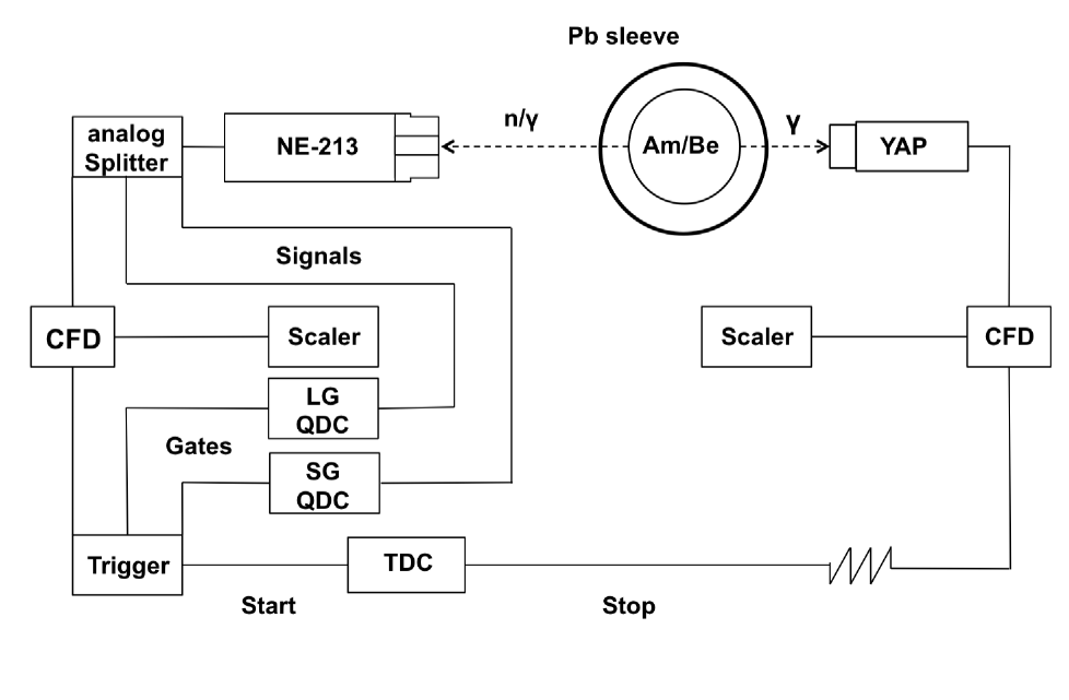
A block diagram of the experiment configuration is shown in Fig. 4. The Am/Be source was placed so that its cylindrical-symmetry axis corresponded to the vertical direction in the lab at the center of a 3 mm thick cylindrical Pb sleeve (with the same orientation) to attenuate the 60 keV gamma-rays associated with the decay of 241Am444 The half-value layer for Pb for 60 keV gamma-rays is 1 mm.. A YAP detector was placed with its crystal approximately 5 cm from the Am/Be source at source height. The crystal orientation was such that its cylindrical symmetry axis also corresponded to the vertical direction in the lab. This detector triggered overwhelmingly on the 4.44 MeV gamma-rays radiating from the source which came from the decay of the first excited state of 12C. A NE-213 detector was placed approximately 68 cm from the Am/Be source at source height. The cylindrical symmetry axis of the NE-213 detector pointed directly at the center of the source. This detector triggered on both 4.44 MeV gamma-rays and fast neutrons coming from the source, as well as cosmic rays and room background555 Room background consisted primarily of 2.23 MeV gamma-rays associated with neutron capture on the hydrogen in the water and paraffin used as general radiation shielding about the source..
2.5 Electronics and data acquisition
The analog signals from the YAP trigger detector and the NE-213 detector were passed to LRS 2249A and 2249W CAMAC charge-to-digital converters (QDCs) and PS 715 NIM constant-fraction (timing) discriminators. The resulting logic signals from the discriminators were passed to LRS 2228A CAMAC time-to-digital converters (TDCs) and LRS 4434 scalers. These signals were recorded on an event-by-event basis for offline processing using a LINUX PC-based data-acquisition (DAQ) system exploiting the ROOT [16] data-analysis framework. Connections to VME and CAMAC crates were respectively facilitated by a SBS 616 PCI-VME bus adapter and a CES 8210 CAMAC branch driver. In YAP calibration mode, signals from a YAP detector were periodically employed to trigger the DAQ and thus monitor the gains of the YAP detectors. In TOF mode, signals from the NE-213 detector were used to trigger the DAQ so that the gain of the NE-213 detector was continuously monitored. The NE-213 detector QDCs included a 60 ns short-gated (SG) QDC and a 500 ns long-gated (LG) QDC, both of which opened 25 ns before the analog pulse arrived. The NE-213 detector also provided the start trigger for the TOF TDC. The YAP trigger provided the stop trigger for the TOF TDC. By triggering our data-acquisition system on the NE-213 detector, we avoided unnecessary deadtime processing events seen only by the YAPs. Two particular source-related occurrences were of special interest: 1) a fast neutron detected in the NE-213 detector starting the TOF TDC with the corresponding 4.44 MeV gamma-ray detected in the YAP detector stopping it; and 2) prompt, time-correlated gamma-ray pairs emitted from the source being detected in coincidence in the NE-213 and YAP detectors (see below).
3 Results
Figure 5 shows a contour plot of the energy deposited in the NE-213 detector as a function of “pulse shape” (PS, see below) versus “L” (the energy deposited in the LG QDC). PS was calculated using the “tail-to-total” method [17, 18, 19]; namely, the difference in the energies registered by the LG and SG QDCs was normalized to the energy registered by the LG QDC. As the NE-213 scintillator responded differently666 In the liquid scintillator NE-213, gamma-ray scintillations are fast while neutron-associated scintillations have pronounced slow components. Analysis of the time structure of the scintillation components leads to particle identification (PID) and is known as pulse-shape discrimination (PSD). to gamma-ray and fast-neutron events, the two distinct distributions appeared in the PS versus L contour plot. Particle identification (PID) based solely upon the pulse-shape discrimination (PSD) characteristics of the NE-213 detector was good, although some overlap between the distributions existed in the vicinty of PS 0.2.
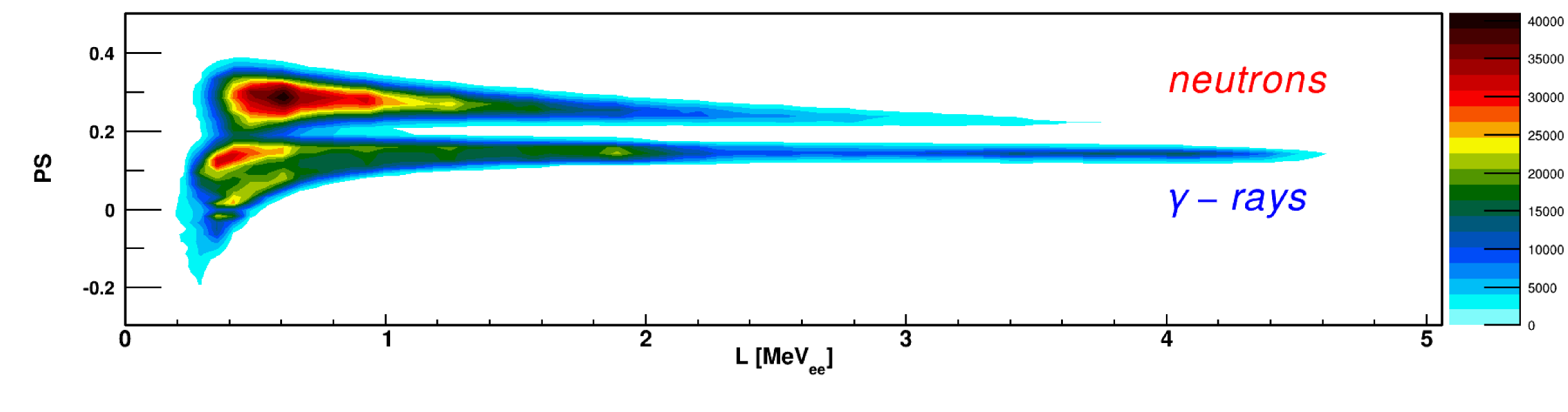
Figure 6 presents the time-of-flight distribution of the data shown in Fig. 5. No software cut on L was applied in mapping the data from Fig. 5 to Fig. 6. The hardware threshold was 250 keVee. The top panel shows a contour plot of PS versus time-of-flight. Time-of-flight based PID is clearly excellent. The bottom panel shows the projection of events from the top panel onto the time-of-flight axis subject to a PS 0.19 cut to separate neutrons from gamma-rays. The sharp (blue) unshaded peak centered at about 2 ns is known as the “-flash”777 The instant of the production in the source of the correlated pair of events which produce the time-of-flight data is known as “T0” and is located at a time-of-flight of 0 ns.. The gamma-flash corresponds to a pair of prompt, time-correlated gamma-rays produced in the source which triggered both the NE-213 detector and the YAP detector. The 1.8 ns FWHM of the gamma-flash is consistent with the timing jitter on our PMT signals. The tail of events to the right of the gamma-flash corresponds to non-prompt gamma-rays888 A non-prompt gamma-ray can result from inelastic neutron scattering. and randoms (see below). The broad (red) shaded peak centered at about 25 ns corresponds to time-correlated 4.44 MeV gamma-ray/fast-neutron pairs where the fast neutron triggered the NE-213 detector while the 4.44 MeV gamma-ray triggered the YAP detector. A neutron with time-of-flight measured in this manner has been tagged. The very low level of background consists of randoms. Random events arose when the NE-213 detector started the time-of-flight measurement, but no correlated stop was received from the YAP. Typical random events included cosmic rays, room background, Am/Be neutrons not correlated with a 4.44 MeV gamma-ray, and Am/Be neutrons where the 4.44 MeV gamma-ray was missed due to YAP inefficiency or geometry.
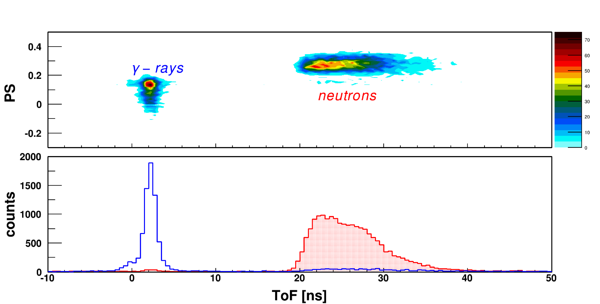
Figure 7 shows our tagged-neutron results together with previous results, the ISO 8529-2 reference neutron radiation spectrum for Am/Be999 While we employ the reference spectrum in our discussion of results, the interested reader may prefer Refs. [40] and [41]. , and theoretical calculations. Our data represent yield – they have not been corrected for neutron-detection efficiency or detector acceptance. In all 3 panels, the maximum values of the spectra at 3 MeV have been normalized to our distribution. The reference neutron radiation spectrum is shown in the top panel together with the full-energy neutron spectrum of Lorch [20] which is widely quoted in conjunction with work with Am/Be sources. Agreement between the Lorch data and the reference spectrum is very good between 2.5 MeV and 10 MeV. The reference spectrum shows some strength above 10 MeV which Lorch did not observe. Our data show no strength above 7 MeV due to the neutron-tagging procedure – 4.44 MeV potentially available to the neutron are “lost” to the creation of the de-excitation gamma-ray. This is neither an acceptance nor an efficiency effect, it is purely energetics. The reference spectrum shows considerable strength below 2.5 MeV. Our data also show some strength in this region. The Lorch data do not. The sharp cutoff at about 2.5 MeV in the Lorch data is not directly discussed in the reference, but based upon its appearance in spectra from several different sources all measured with the same apparatus, we attribute it to an analysis threshold cut as it lies well above their quoted neutron-detector threshold of 1 MeV. Our hardware threshold was 250 keVee corresponding to a neutron energy of 1.3 MeV, and no analysis threshold cut was employed. The agreement between our data, those of Lorch, and the reference spectrum between 2.5 and 5 MeV (in the region of overlap) is excellent. The method of tagging the 4.44 MeV de-excitation gamma-ray and a comparable Am/Be source101010 Their source capsule was slightly smaller and emitted about 50% more neutrons per second. were employed by Geiger and Hargrove [37] in obtaining the results shown in the middle panel. Both the neutrons and the gamma-rays from their source were detected in Naton 136 plastic scintillators. Agreement with our results is very good. We attribute the small difference in the strengths observed in the two measurements to neutron-detection efficiency and acceptance effects which we do not consider. We attribute the relative broadening of their measured neutron distribution with respect to ours to their quoted poorer than 12% energy resolution for neutron detection, which based on the numbers quoted in their manuscript, we gather was calculated at 2 MeV. At 2 MeV, based upon our gamma-flash FWHM of 1.8 ns, time-of-flight path length of 0.675 m, and detector half-depth of 3.1 cm, our energy resolution was 11%. At 4 MeV, our energy resolution was 19%. The three independent theoretical calculations of the tagged-neutron yield shown in the bottom panel come from Vijaya and Kumar [22], Van der Zwan [38], and De Guarrini and Malaroda [39]. The details of these calculations are beyond the scope of this paper, but clearly all three are in reasonable agreement both with each other as well as our results. We conclude we are tagging neutrons.
4 Summary
We have employed shielding, coincidence, and time-of-flight measurement techniques to tag fast neutrons emitted from an Am/Be source as a first step towards developing a source-based fast-neutron irradiation facility. The resulting continuous polychromatic energy-tagged neutron beam has a measured energy structure that agrees qualitatively with both previous measurements and theoretical calculations. We conclude that our approach works as expected, and anticipate that it can provide a cost-effective means for detector characterization and tests of shielding. We note that this technique will work equally well for all Be-compound neutron sources.
Acknowledgements
We thank the Photonuclear Group at the MAX IV Laboratory for providing access to their experimental hall and Am/Be source. We acknowledge the support of the UK Science and Technology Facilities Council.
References
- [1] J. Walker, Phys. Technol. 13 (1982) 239.
- [2] United States Committee on Army Science and Technology for Homeland Defense, Board on Army Science and Technology, Division on Engineering and Physical Sciences, National Research Council, Indications and Warning Technologies, in Science and Technology for Army Homeland Security: Report 1, National Academies Press (2003).
- [3] International Workshop on Fast Neutron Detectors and Applications (FNDA2006), University of Capetown, South Africa (2006), Proceedings of Science (FNDA2006). http://pos.sissa.it/cgi-bin/reader/conf.cgi?confid=25.
- [4] 2nd International Workshop on Fast Neutron Detectors and Applications (FNDA2011), Kibbutz Ein Gedi, Israel (2011), JINST 7 C (2012). http://iopscience.iop.org/1748-0221/focus/extra.proc19.
- [5] Proceedings from the workshop on Neutron, Neutrino, Nuclear, Muon and Medical Physics at ESS, Lund, Sweden (2009). http://www.hep.lu.se/staff/christiansen/proceeding.pdf.
- [6] R. Chandra, G. Davatz, U. Gendotti, A. Howard, IEEE NSS/MIC (2010) 508.
- [7] W.C. Lyons, G.J. Plisga, Drilling and Well Completions, Reservoir Engineering, in Standard Handbook of Petroleum and Natural Gas Engineering, 2nd edition, Elsevier Science (2011).
- [8] R. Chandra, G. Davatz, H. Friederich, U. Gendotti, D. Murer, JINST 7.03 (2012) C03035.
- [9] P. Peerani, A. Tomanin, S. Pozzi, J. Dolan, E. Miller, M. Flaska, M. Battaglieri, R. De Vita, L. Ficini, G. Ottonello, G. Ricco, G. Dermody, C. Giles, Nucl. Instr. and Meth. in Phys. Res. A 696 (2012) 110.
- [10] Workshop on fast neutron applications at spallation sources, Abingdon, UK (2013). http://plone.esss.lu.se/.
- [11] M.R. Islam, M.I. Khan, Current Practice in Well Logging, Reservoir Engineering and Secondary Recovery, in The Petroleum Engineering Handbook: Sustainable Operations, Elsevier Science (2013).
- [12] J.M. Lewis, D. Raetz, D. Murer, K.A. Jordan, 3rd International Conference on Advancements in Nuclear Instrumenation Measurment Methods and their Applications, Marseille, France (2013). http://ieeexplore.ieee.org/stamp/stamp.jsp?tp=&arnumber=6728031.
- [13] A. Tomanin, J. Paepen, P. Schillebeeckx, R. Wynants, R. Nolte, A. Lavietes, Nucl. Instr. and Meth. in Phys. Res. A 756 (2014) 45.
- [14] J.M. Lewis, R.P. Kelley, D. Murer, K.A. Jordan, Appl. Phys. Lett. 105 (2014) 014102.
- [15] supplied by High Tech Sources Limited, Unit 6, Moorbrook, Southmead, Industrial Estate, Didcot, Oxfordshire, UK OX11 7HP; https://www.hightechsource.co.uk/. For details see www.hightechsource.co.uk/Legacy/Resources/Americium-Beryllium.pdf.
- [16] R. Brun and Fons Rademakers, ROOT - An Object Oriented Data Analysis Framework, Proceedings AIHENP’96 Workshop, Lausanne, Sep. 1996; Nucl. Instr. and Meth. in Phys. Res. A 389 (1997) 81-86. See also http://root.cern.ch/.
- [17] A. Jhingan, H. Singh, R.P. Singh, K.S. Golda, P. Sugathan, S. Mandal, R.K. Bhowmik, Nucl. Instr. and Meth. in Phys. Res. A 585 (2008) 165.
- [18] A. Lavagno, G. Gervino and C. Marino, Nucl. Instr. and Meth. in Phys. Res. A 617 (2010) 492.
- [19] I.A. Pawełczak, S.A. Ouedraogo, A.M. Glenn, R.E. Wurtz, L.F. Nakae Nucl. Instr. and Meth. in Phys. Res. A 711 (2013) 21.
- [20] E.A. Lorch, Int. J. Appl. Radiat. Is. 24 (1973) 585.
- [21] testing performed at National Physical Laboratory, Teddington, Middlesex, UK TW11 0LW on 24 January 2012.
- [22] A.D. Vijaya, A. Kumar, Nucl. Instrum. and Meth. 111 (1973) 435.
- [23] A.A. Mowlavi, R. Koohi-Fayegh, Appl. Radiat. Isot. 60 (2004) 959.
- [24] Zhenzhou Liu, Jinxiang Chen, Pei Zhu, Yongming Li, Guohui Zhang, Appl. Radiat. Isot. 65 (2007) 1318.
- [25] Scionix Holland BV. http://www.scionix.nl.
- [26] M. Moszyński, M. Kapustab, D. Wolski, W. Klamra, B. Cederwall, Nucl. Instr. and Meth. in Phys. Res. A 404 (1998) 157.
- [27] Hamamatsu Photonics. http://www.hamamatsu.com.
- [28] NE-213 is no longer produced. Eljen Technologies offers EJ-301 (http://www.eljentechnology.com/index.php/products/liquid-scintillators/71-ej-301) while Saint Gobain offers BC-501 (http://www.detectors.saint-gobain.com/uploadedFiles/SGdetectors/Documents/Product_Data_Sheets/BC501-501A-519-Data-Sheet.pdf).
- [29] http://www.eljentechnology.com/index.php/products/paints/87-ej-520.
- [30] http://www.us.schott.com/borofloat/english/index.html for details. Supplied by Glasteknik i Emmaboda AB, Utvägen 6 SE-361 31 Emmaboda, Sweden.
- [31] Araldite is a registered trademark of Huntsman. http://www.araldite2000plus.com.
- [32] Viton is a registered trademark of DuPont Performance Elastomers LLC.
- [33] Poly(methyl-methacrylate), also known as acrylic, plexiglass, and lucite. Supplied by Nordic Plastics Group AB, Bronsyxegatan 6, SE-213 75 Malmö, Sweden.
- [34] http://www.eljentechnology.com/index.php/products/paints/86-ej-510.
- [35] www.et-enterprises.com/files/file/Pmtbrochure11.pdf for details.
- [36] H.H. Knox, T.G. Miller, Nucl. Instrum. and Meth. 101 (1972) 519.
- [37] K.W. Geiger, C.K. Hargrove, Nucl. Phys. 53 (1964) 204.
- [38] L. Van der Zwan, Can. J. Phys. 46 (1968) 1527.
- [39] F. De Guarrini, R. Malaroda, Nucl. Instr. and Meth. 92 (1971) 277.
- [40] J.W. Marsh, D.J. Thomas, M. Burke, Nucl. Instr. and Meth. in Phys. Res. A 366 (1995) 340.
- [41] Y. Chen, X. Chen, J. Lei, L. An, X. Zhang, J. Shao, P. Zheng, X. Wang, Science China Physics, Mechanics & Astronomy 57 (2014) 1885.