Integration algorithms of elastoplasticity
for ceramic powder compaction
Abstract
Inelastic deformation of ceramic powders (and of a broad class of rock-like and granular materials), can be described with the yield function proposed by Bigoni and Piccolroaz (2004, Yield criteria for quasibrittle and frictional materials. Int. J. Solids and Structures, 41, 2855-2878). This yield function is not defined outside the yield locus, so that ‘gradient-based’ integration algorithms of elastoplasticity cannot be directly employed. Therefore, we propose two ad hoc algorithms: (i.) an explicit integration scheme based on a forward Euler technique with a ‘centre-of-mass’ return correction and (ii.) an implicit integration scheme based on a ‘cutoff-substepping’ return algorithm. Iso-error maps and comparisons of the results provided by the two algorithms with two exact solutions (the compaction of a ceramic powder against a rigid spherical cup and the expansion of a thick spherical shell made up of a green body), show that both the proposed algorithms perform correctly and accurately.
Keywords: Yield function; granular materials; forming of ceramic granulate; integration algorithms of elastoplasticity; cavity expansion.
1 Introduction
Granular and geological materials are employed for many industrial purposes: shock and vibration absorbers, fire protection, thermal barriers, refractory products, wear protectors, electric isolators, and catalysts. They are characterized by pressure-sensitive yielding and dilatant/contractant inelastic behaviour222 These mechanical behaviours are observed in: ceramic and metal powders [36, 37, 6, 24, 25], concrete [4], geomaterials [14, 34, 17, 18, 19, 21, 22, 31, 33, 46, 53], masonry [3, 20, 51], but also metals [10, 15, 16, 23, 27, 32, 38, 52], high strength alloys [5], and shape memory alloys [28, 29, 41, 30, 42, 44, 45, 49]. . Several yield functions have been introduced for the mechanical description of these materials, which have to satisfy different requirements, among which, the most important are convexity and smoothness, two requisites met by the yield function proposed by Bigoni and Piccolroaz [9] (see also [35, 7]), henceforth referred to as the ‘BP yield function’. Moreover, this function has an extreme ‘deformability’, thus results particularly appropriate to describe the granular/solid transition occurring during forming of ceramic powders [11, 48], a crucial process in the production of many ceramic products.
Used in the context of elastoplastic modelling, the BP yield function introduces the problem that to be convex, it has been defined outside certain regions in the stress-space. Therefore, in its original form, the PB yield function cannot be implemented within an elastoplastic integration scheme, if a gradient-based return-mapping algorithm is used, for which the gradient of the yield function is needed everywhere in the stress-space [47]. If a non-convex version of the BP yield function (obtained by squaring the terms) is implemented with a return-mapping algorithm, wrong results can be produced, as a specific example will demonstrate.
The problem of the BP yield surface is also common to other yield surfaces for geomaterials [12], so that the aim of the present article is to overcome the difficulty by proposing two algorithms: one is based on a forward Euler technique with a correction based on a ‘centre-of-mass’ return scheme, fully applicable to the original form of the BP yield function (defined outside the yield surface), and another based on a cutoff- substepping return-mapping algorithm that can be applied on the squared (and non-convex) version of the BP yield function. Iso-error maps and comparisons with two model problems allowing for a semi-analytical solution (the forming of a ceramic powder pressed against a rigid spherical cup and the expansion of a green body spherical shell subject to internal pressure) show that both algorithms perform correctly, with an accuracy comparable in certain regions of the stress state, even if there are regions where each algorithm is superior to the other. In particular, the ‘centre-of-mass’ algorithm is faster that the other, but less accurate near vertices of the deviatoric yield surface, while the cutoff-substepping return-mapping algorithm is always more accurate than the other, but can become slow for stress states near the vertices of the meridian yield surface. Finally, we may conclude that, although both algorithms have their advantages and limitations, generally speaking the cutoff-substepping return-mapping algorithm can eventually be preferred.
2 The ‘centre of mass’ integration algorithm
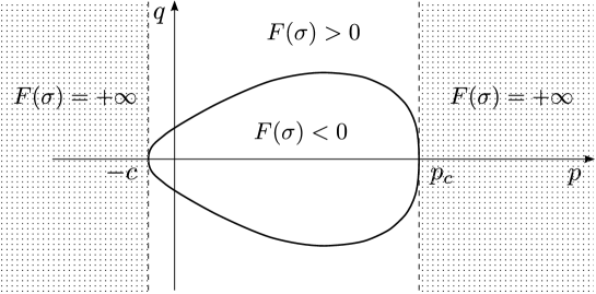
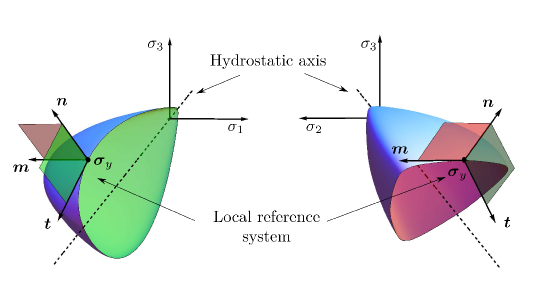
As mentioned in the introduction, the problem with the BP yield function is that it is defined in some regions outside the elastic domain (for ), Fig. 1. Therefore, an integration algorithm based on a standard return mapping technique cannot work, so that the purpose of this Section is to introduce an explicit forward Euler algorithm to solve this problem (while an implicit algorithm will be presented in the next Section defined on a ‘squared version’ of the yield function).
2.1 The BP yield surface and its centre of mass
Bigoni and Piccolroaz [9] (see also [35]) have introduced a new yield function for isotropic materials (called ‘BP’ in the following), defined in terms of the stress tensor by
| (1) |
where, defining the parameter as
| (2) |
the meridian and deviatoric functions are respectively written as333 The expression (3)2 of was proposed by Podgórski [39, 40] and independently by Bigoni and Piccolroaz [9].
| (3) |
in which , and (the Lode’s angle) are the following stress invariants
| (4) |
functions of the second and third invariant of the deviatoric stress
| (5) |
being the identity tensor.
The yield function (1)–(3) is convex when the seven material parameters defining the meridian shape function and the deviatoric shape function lie within the following intervals
| (6) |
Centre of mass of the yield surface
The numerical integration algorithm that will be developed later is based on the knowledge of the centre of mass of the yield surface. This, with reference to Fig. 2, can be obtained as follows.
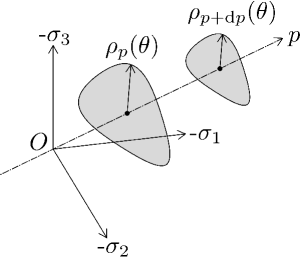
We begin noting that the yield surface possesses the isotropy symmetries in the deviatoric plane (see [9]), therefore, the centre of mass of the yield surface lies on the hydrostatic axis. The infinitesimal area of the deviatoric section can be evaluated as
| (7) |
where
| (8) |
is the radius of the surface boundary evaluated with respect to the hydrostatic axis, so that the area of the deviatoric section is expressed as
| (9) |
On application of the definition of the centre of mass
| (10) |
provides the coordinate of the centre of mass of the BP yield surface along the hydrostatic axis
| (11) |
a formula involving all the meridian parameters of the yield function, except .
2.2 The ‘centre of mass’ return algorithm
We propose a numerical integration procedure for rate elastoplastic constitutive equations based on a return algorithm which is geometrically sketched in Fig. 3 and can be syntetically described with reference to Box 1.

In particular, starting from a given state at a step [point (1) in Box 1] and after the usual trial elastic step [point (2)], the stress point at yielding is found along the line joining the trial and the initial state [point (3)]; from this point, after the purely elastic strain is eliminated from the strain increment [point (4)], a new stress increment is found using the tangent elastoplastic operator [point (5)]; the plastic strain increment is updated [point (6)]; and finally, a return on the updated yield surface is performed along the line joining with the centre of mass of the yield surface [points (7)–(8)].
Box 1: The ‘centre of mass’ integration algorithm
(1)
Given an initial state at step , described by the variables , , and given a strain
increment ;
(2)
evaluate the elastic trial solution
(3)
along the line from to find the stress point at yielding
(4)
evaluate the elastic deformation increment corresponding to
(5)
evaluate the stress increment via the tangent elastoplastic operator
(6)
update the plastic deformation
(7)
find the stress on the updated yield surface
(8)
update the plastic deformation for the final stress state on the yield surface
(9)
EXIT.
There are two ‘find’ in the procedure explained in Box 1: the first is at point (3) and the second is at point (7). Both correspond to a root-finding procedure for a scalar function (the yield function) of tensorial variable (the stress), which can be pursued with different numerical techniques, so that we have employed a bisection method. Regarding the ‘find’ at point (3), the zero of is sought along the segment joining with , while no directions are a-priori prescribed for returning on the yield surface from the stress state at point (5). We propose to find the zero of along the segment drawn from to the centre of mass of the yield surface, [defined by parameter , eq. (11)].
Note finally that the presented numerical algorithm has the inconvenient typical of explicit methods, for which there is a small discrepancy at the end of the procedure, in the sense that the stress point lies on a yield surface which does not correspond to the updated values of hardening. A procedure alternative to the centre-of-mass algorithm is introduced in the next section.
3 The ‘cutoff-substepping’ integration algorithm
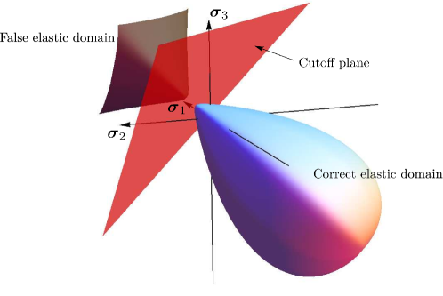
As an alternative to the forward Euler procedure with ‘centre of mass’ return correction introduced in the previous section, we propose an implicit integration scheme. Since the standard return mapping algorithm does not work in a zone of the stress-space, this zone can be delimited by introducing a cutoff plane orthogonal to the hydrostatic axis, so that a new algorithm can be set up in which the return mapping scheme is augmented of a substepping when the trial elastic stress falls within that zone. In particular, if the trial elastic solution falls on the same side of the plane as the starting point, the return mapping algorithm correctly converges (as demonstrated in Section 3.1), while, if it falls beyond the cutoff plane, an iterative subincrementation is performed, in which the strain increment is subdivided and the return mapping is iteratively applied with successive updates of the BP yield function, so that, eventually, the entire initial step will be performed remaining within the correct stress zone.
The position of this cutoff plane depends on shape and size of the BP yield surface, see Fig. 4, and can be determined as follows.
3.1 The squared BP yield function and the cutoff plane
The squared BP yield function is obtained by squaring the terms in equation (3), so that its meridian part (divided by ) can be written as
| (12) |
The first and second derivatives of this function with respect to are
| (13) |
and
| (14) |
respectively. Note that the squared BP yield function is differentiable (its first and second derivatives are defined everywhere), but, in general, is no longer convex and displays a so-called ‘false elastic domain’ (a nomenclature introduced by Brannon and Leelavanichkul [12]), visible in Fig. 4. For this reason, the Newton-Raphson algorithm
| (15) |
in general fails to converge. Nevertheless, it is possible to demonstrate that, for the squared BP yield function, a non-convex region exists in which the Newton-Raphson method still converges, despite the non-convexity. The region is delimited by the above-introduced cutoff plane, which position can be determined as follows.
Position of the cutoff plane
Let us consider the situation sketched in Fig. 5.

The generic points and lie on the meridian function, so that it is possible to calculate in those points the tangents
| (16) |
and
| (17) |
where a prime denotes the derivative with respect to . If we impose that and , we obtain the following non-linear algebraic system
| (18) |
with the unknowns and ; these values, that can be calculated numerically, define the region in which the Newton-Raphson algorithm can be still used, even though the squared BP yield function is not convex.
As a conclusion, is the value defining the position of the cutoff plane, to be used in the subincrementation scheme, as shown in Box 2 (note that is not needed, since in the integration algorithm the trial elastic stress always lies outside the elastic domain).
Box 2: The ‘cutoff-substepping’ integration algorithm
(1)
Given an initial state at step , described by the variables , , and given a strain
increment ;
(2)
Set and (where defines the substep interval);
(3)
INITIALIZE: all variables are set equal to the value at the initial step ;
(4)
DO , ;
(5)
Evaluate the elastic trial solution
(6)
Calculate and by solving eq. (18);
(7)
Check position with respect to the cutoff plane
IF GOTO Standard Return Mapping;
(8)
Substepping procedure
ELSE AND ;
(9)
GOTO (3)
4 The numerical performance: finite step accuracy
The numerical performance of the centre-of-mass integration technique has been tested by comparing results obtained for a prescribed finite step of deformation (taken in different directions in the hyperspace of symmetric tensors as elucidated in Table 1) with those obtained with the cutting-plane return-mapping technique [47] applied to the ‘squared-version’ of the BP yield surface, without subincrementation. In this way, it will become evident that for certain values of the trial elastic stress convergence will not occur for the latter algorithm.
| Deformation | |||
| Test 1 | Isotropic compression | ||
| Test 2 | Isotropic traction | ||
| Test 3 | Negative uniaxial deformation | ||
| Test 4 | Positive uniaxial deformation | ||
| Test 5 | Triaxial compression | ||
| Test 6 | Triaxial extension | ||
| Test 7 | Shear | ||
| 0 | |||
The comparison between the two integration algorithms has been performed by assuming:
-
•
a form of the yield surface, namely,
-
•
elastic parameters in terms of Lamé constants
-
•
linear strain-hardening.
Note that the above parameters have been selected to be representative of a concrete-like material and the linear-hardening elastoplastic model has been implemented as a Umat routine for Abaqus (Ver. 6.10).
The strain steps prescribed in Table 1 for testing the capability of the integration algorithms and the corresponding trial elastic stresses are reported together with the strain-space and stress-space representations of the BP meridian sections, respectively in the upper and lower parts of Fig. 6, where is the Lode’s angle, eq. (4)3. The trial elastic stresses in the deviatoric plane of the BP yield surface are reported in the central part of Fig. 6.
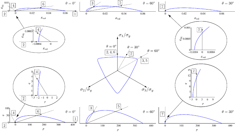
Note that the prescribed trial stresses have been given so that, in all cases, exactly the 20% of its norm lies outside the elastic domain, . Results, in terms of stress and plastic strain reached at the end of the procedure, are reported in Tab. 2 for tests 1 to 6, while results of the test 7 are reported in Tabs. 3 and 4. In addition to the two algorithms under testing, a so-called ‘exact’ result has also been included. This is obtained through successive subdivision of the strain increment into a sufficiently large number of subincrements to achieve convergence within a high tolerance (so that the relative error between the last two subincrements lies below ).
For the isotropic compression deformation path (‘test 1’) the return mapping algorithm fails to converge, as a consequence of the lack of convexity of the squared-version of the BP yield function, and therefore results are not reported in the table.
| Stress | Error | Plastic strain | Error | |||||
|---|---|---|---|---|---|---|---|---|
| % | % | |||||||
| Test 1 | Centre of mass | 0.05 | 0.53 | |||||
| Return mapping | ||||||||
| Exact | ||||||||
| Test 2 | Centre of mass | 0.00 | 0.00 | |||||
| Return mapping | 0.00 | 0.00 | ||||||
| Exact | ||||||||
| Test 3 | Centre of mass | 0.89 | 8.56 | |||||
| Return mapping | 0.45 | 4.25 | ||||||
| Exact | ||||||||
| Test 4 | Centre of mass | 0.23 | 2.14 | |||||
| Return mapping | 0.31 | 2.93 | ||||||
| Exact | ||||||||
| Test 5 | Centre of mass | 0.04 | 0.16 | |||||
| Return mapping | 0.09 | 1.08 | ||||||
| Exact | ||||||||
| Test 6 | Centre of mass | 0.11 | 1.52 | |||||
| Return mapping | 0.00 | 0.22 | ||||||
| Exact | ||||||||
| Stress | Error | ||||
|---|---|---|---|---|---|
| % | |||||
| Test 7 | Centre of mass | 0.61 | |||
| Return mapping | 0.54 | ||||
| Exact | |||||
| Plastic strain | Error | ||||
|---|---|---|---|---|---|
| % | |||||
| Test 7 | Centre of mass | 6.64 | |||
| Return mapping | 5.92 | ||||
| Exact | |||||
Iso-error maps have been plotted to display the error trend of the two algorithms in the stress-space for a set of different strain increments, chosen with the condition that the trial elastic solutions lie respectively in the meridian (denoted as in Fig. 7 on the left) and deviatoric (denoted as in Fig. 7 on the right) planes.
The iso-error maps plotting ranges have been chosen as follows:
| (19) |
where is the considered stress at yielding
| (20) |
The iso-error maps are reported in Fig. 8–11, assuming as yield stresses those corresponding to the tests 3, 4, 5, and 6 of Tab. 1, graphically represented in Fig. 6.
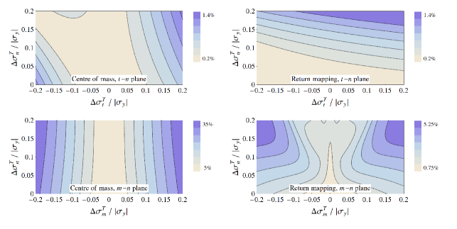
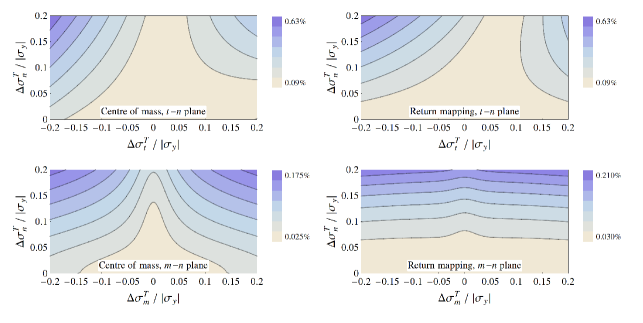
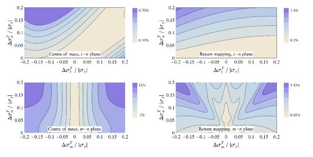
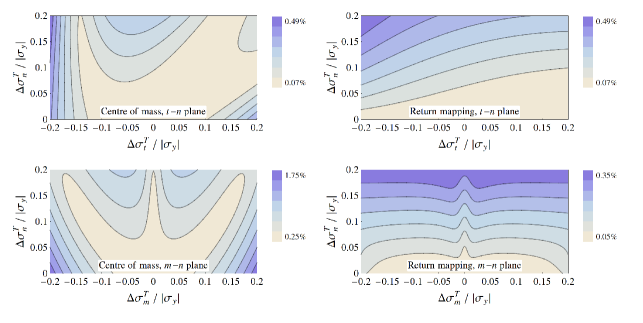
It can be noted from Figs. 8 and 10 (bottom, left) that the centre-of-mass algorithm has a low accuracy when the yield stress lies near the corner of the deviatoric section (see Fig. 6, central part, tests 3 and 5) and the stress increment is not radial. On the other hand, the accuracy is high in both and planes, when the yield stress lies near the flat parts of this section (see Fig. 6, central part, tests 4 and 6), as shown in Figs. 9 and 11.
5 Comparison with semi-analytical solutions
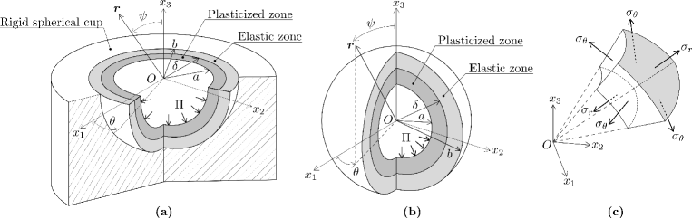
Numerical results obtained by employing the proposed algorithms have been compared with semi-analytical solutions of a simple compaction problem and a deformation of a green body. In particular, in Section 5.1, the forming of a thick perfectly-plastic layer of ceramic powder is considered, pressed against a rigid spherical cup, see Fig. 12a. Moreover, a thick spherical shell of a green body is considered in Section 5.2, subjected to an internal uniform pressure with a traction-free external boundary and expanded until collapse, corresponding to complete plasticization, see Fig. 12b. Due to the spherical symmetry of both the problems, it is possible in both cases to obtain accurate semi-analytical solutions for the stress field by direct numerical integration of the equilibrium equations.
These benchmark problems, differing only in the boundary conditions, are used to check the accuracy and efficiency of the proposed algorithms. They represent only model problem simulations of industrial processes and cannot be considered fully realistic, since hardening (and therefore the evolution of the yield surface) is neglected, so that the increase in cohesion is not taken into account.
The problem of the expansion of a thick spherical shell is interesting in itself, due to the applications in geotechnics, and it has been previously solved under a number of hypotheses [26, 8, 13, 43, 50], although never with the BP yield function. The problem of compaction of a layer of powder against a rigid cup was previously not addressed in analytically.
For both problems, the inner and outer radii of the shell are denoted with and respectively, while the internal pressure is , which is assumed to increase from zero to the maximum value corresponding to the full plasticization of the shell. Since the geometry shows radial symmetry, we assume a spherical coordinate system. The solution is known in the case of perfect plasticity with the Tresca yield criterion [26], so that our objective is to generalize the solution to the BP yield criterion.
Due to the spherical symmetry, the stress and deformation depend only on the radius . The non-vanishing deformation radial azimuthal, and polar components are respectively
| (21) |
where is the radial displacement. The compatibility equation is
| (22) |
while the equilibrium equation in spherical coordinates is
| (23) |
to be complemented by the boundary conditions.
The elastic constitutive equations are
| (24) |
where is the elastic Young modulus and the Poisson’s ratio. The Tresca yield criterion coincides (under the current assumptions) with the von Mises criterion, which can be written as
| (25) |
where is the uniaxial yield stress, while the BP yield criterion (1) writes now in the following form
| (26) |
The elastic solution.
Using equations (22), (23) and (24) we obtain
| (27) |
This equation together with eq. (23) forms a system of ODEs, which can be solved exactly and the solution is given by
| (28) |
where and are constants to be defined through the boundary conditions. The associated deformation and displacement fields are obtained from (24) and (21) and read
| (29) |
| (30) |
5.1 Compaction of a thick layer of perfectly-plastic material obeying the BP yield condition against a rigid spherical cup
For the compaction problem of a thick layer against a rigid spherical cup, Fig. 12a, the boundary conditions write as follows
| (31) |
where is the internal pressure. The material parameters defining the shape of the BP yield surface have been chosen to be representative of alumina powder (Piccolroaz et al., 2006), namely
Note that, since hardening and increasing of cohesion are neglected, we assume an initial state corresponding to an intermediate stage of a densification process.
5.1.1 The elastic solution
Initially the problem is purely elastic, which occurs when the internal pressure is sufficiently small, say, , where is defined as the inner pressure producing the initiation of yielding at the inner radius of the shell.
The solution (28)–(30) together with boundary conditions (31), provides the following stress field within the thick spherical layer, ,
| (32) |
| (33) |
For the von Mises yield criterion, the critical yield pressure is represented by the stress state satisfying
| (34) |
and can be evaluated as
| (35) |
In the following calculations has been assumed. For the BP yield criterion, the critical yield pressure corresponds to a stress state satisfying
| (36) |
so that can be evaluated as the numerical solution of the above equation and it can be numerically shown that the plasticization starts from the inner surface of the layer, .
5.1.2 The elasto-plastic solution
The elasto-plastic solution holds for an internal pressure , which implies both elastic and plastic deformation of the layer. The plastic flow starts from the inner surface of the layer and propagates within a spherical region with inner radius and outer and moving toward . The remaining part of the layer, namely, for , behaves as an elastic layer with inner radius and outer , subject to an internal pressure at the interface with the plasticized zone.
Assuming that the yield pressure at the interface is , a generic yield criterion writes as
| (37) |
which provides a relation between and . For example, the pressure at the interface for the von Mises criterion can be obtained from eq. (35) imposing as
| (38) |
whereas for the BP criterion the pressure has to be evaluated numerically.
The solution for the elastic zone () can be obtained from eqs. (32) and (33) where and are replaced, respectively, by and which are given by (37), so that the stresses become
| (39) |
| (40) |
Hence the elastic part of the solution is known as the relation between the radius and the pressure is known.
The solution for the plasticized zone () is obtained from the algebraic-differential system composed by the equilibrium equations (23), the boundary conditions (31), and the yield condition (25) or (26) (depending on the criterion assumed). This system writes as
| (41) |
which has been solved analytically for von Mises yield and numerically for the BP yield function. In particular, the system (41) admits for von Mises the following solution
| (42) |
and the relation between and the internal pressure writes as
| (43) |
which is a nonlinear relation. Once a fixed value of the radius , representing the amplitude of the plasticized zone, is chosen, it is possible to obtain the internal pressure and the stresses in every part of the layer, namely for .
Results in terms of radial and polar stress components and the two stress invariants and are reported in Fig. 13 as functions of the through-thickness radius (divided by the mean radius of the spherical layer), together with the numerical results obtained with the two proposed algorithms. Three different plastic boundaries have been considered (corresponding to the 20%, 40% and 60 % of the thickness) for both von Mises and the BP yield criterion.
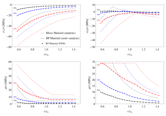
Results presented in the figure fully support the validity of the proposed numerical algorithms, which have given coincident results, superimposed on the semi-analytical solution.
5.2 The expansion of a perfectly plastic thick shell obeying the BP yield condition
For the problem of expansion of a thick spherical shell subjected to an internal uniform pressure, Fig. 12b, the boundary conditions are as follows
| (44) |
where is the internal pressure and the outer boundary is assumed traction-free. The material parameters defining the shape of the BP yield surface have been chosen to be representative of a partially densified ceramic powder, namely
The solution of this problem can be obtained with the same method as that described in Sec. 5.1, since only the boundary conditions are different.
The elastic solution, valid until the internal pressure is sufficiently small, , is given by
| (45) |
For the von Mises yield criterion, , the critical yield pressure is obtained as
| (46) |
whereas for the BP yield criterion, the critical yield pressure is obtained by solving eq. (36) and it can be numerically proven that the plasticization starts from the inner surface of the shell.
The elasto-plastic solution holds for an internal pressure , which implies both elastic and plastic deformation of the shell. The plastic flow starts from the inner surface of the shell and propagates within a spherical region with inner radius and outer and moving toward . The remaining part of the shell, namely, for , behaves as an elastic shell with inner radius and outer , subject to an internal pressure at the interface with the plasticized zone.
The relation between and is obtained by solving eq. (37). For the von Mises criterion is obtained as
| (47) |
whereas for the BP criterion the pressure has to be evaluated numerically.
The solution for the elastic zone, , is given by
| (48) |
The solution for the plasticized zone, , is obtained from the algebraic-differential system (41). This system has a solution with closed form for the simple case of von Mises yield criterion; in this case the stresses take the form
| (49) |
and the relation between and the internal pressure writes as
| (50) |
Once a fixed value of the radius representing the amplitude of the plasticized zone is chosen, it is possible to obtain the internal pressure and the stresses in every part of the shell, namely for .
Results in terms of radial and polar stress components and the two stress invariants and are reported in Fig. 14 as functions of the through-thickness radius (divided by the mean radius of the thick shell), together with the numerical results obtained with the two proposed algorithms. Three different plastic boundaries have been considered (corresponding to the 28%, 55% and 86% of the thickness) for both von Mises and the BP yield criterion.
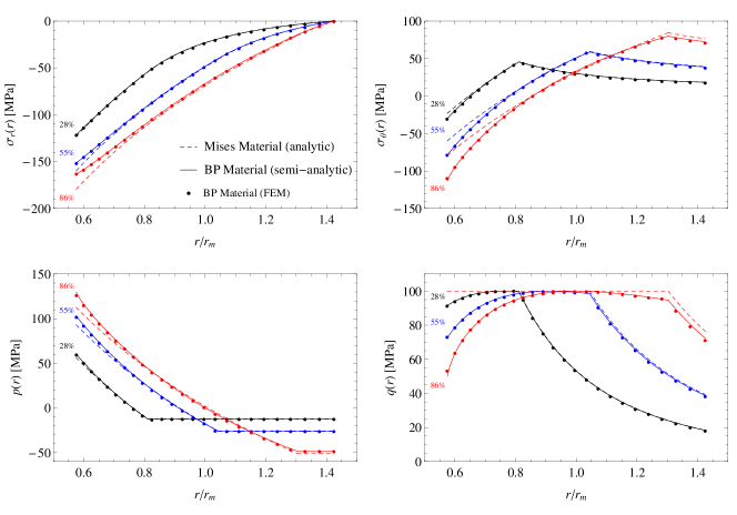
Again the two proposed algorithms have given coincident values, superimposed with the semi-analytical solution, thus confirming once more the validity of the presented numerical approaches.
6 Conclusions
Two different algorithms have been presented for the integration of elastoplastic constitutive equations based on the BP yield function (useful in simulating forming of ceramic powders, deformation of granular bodies and, more in general, damage and failure of rock-like materials). One of the algorithms is based on a forward Euler scheme and the other on a return mapping technique with substepping. Though the former method is in some cases faster, the latter combines accuracy with efficiency and is eventually preferred.
Acknowledgments
Part of this work was prepared during secondment of D.B. at Enginsoft S.p.A. (TN). Discussions with D. Blanco, G. Borzi, M. Gabrielli, L. Gatti are gratefully acknowledged. A.P., D.B. and L.A. gratefully acknowledge financial support from European Union FP7-INTERCER2 project under contract number PIAP-GA-2011-286110. M.P. gratefully acknowledges financial support from European Union FP7-HOTBRICKS project under contract number PIAPP-GA-2013-609758.
References
- [1]
- [2]
- [3] Angelillo, M., Cardamone, L. and Fortunato, A. (2010) A numerical model for masonry-like structures. J. Mech. Materials Structures 5, 583-615.
- [4] Babua, R.R., Benipal, G.S. and Singh, A.K. (2005) Constitutive modelling of concrete: an overview. Asian J. Civil Eng. (Building and Housing) 6, 211-246.
- [5] Bai, Y. and Wierzbicki, T. (2008) A new model of metal plasticity and fracture with pressure and Lode dependence. Int. J. Plasticity 24, 1071-1096.
- [6] Bier, W. and Hartmann, S. (2006) A finite strain constitutive model for metal powder compaction using a unique and convex single surface yield function, Eur. J. Mech. A-Solid. 25, 1009-1030.
- [7] Bigoni, D. (2012) Nonlinear Solid Mechanics. Bifurcation theory and material instability, Cambridge University Press.
- [8] Bigoni, D. and Laudiero, F. (1989), The quasi-static finite cavity expansion in a non-standard elasto-plastic medium, Int. J. Mech. Sci., 31, 825-837.
- [9] Bigoni, D. and Piccolroaz, A. (2004) Yield criteria for quasibrittle and frictional materials. Int. J. Solids Struct. 41, 2855-2878.
- [10] Bolchoun, A., Kolupaev, V.A., Altenbach, H. (2011) Convex and Non-convex Flow Surfaces. Forschung im Ingenieurwesen-Engineering Research 75, 73-92.
- [11] Bosi, F., A. Piccolroaz, M. Gei, F. Dal Corso, A. Cocquio and Bigoni, D. 2013. Experimental investigation of the elastoplastic response of aluminum silicate spray dried powder during cold compaction. J. Europ. Ceramic Soc. Submitted.
- [12] Brannon, R.M. and Leelavanichkul, S. (2010) Received: A multi-stage return algorithm for solving the classical damage component of constitutive models for rocks, ceramics, and other rock-like media. Int. J. Fracture 163, 133 149.
- [13] Cohen T., Masri, R. Durban D. (2009) Analysis of circular hole expansion with generalized yield criteria, Int. J. Solids Struct. 46, 3643-3650.
- [14] Conti, R., Tamagnini, C., DeSimone, A. (2013) Critical softening in Cam-Clay plasticity: Adaptive viscous regularization, dilated time and numerical integration across stress strain jump discontinuities. Comput. Method. Appl. M. 258, 118 133.
- [15] Coppola, T., Cortese, L. and Folgarait, P. (2009) The effect of stress invariants on ductile fracture limit in steels. Eng. Fract. Mech. 76, 1288-1302.
- [16] Coppola, T. and Folgarait, P. (2007) The influence of stress invariants on ductile fracture strain in steels. (in Italian) Proc. XXXVI AIAS Congress, Sept. 4-8, 2007.
- [17] Dal Maso, G., DeSimone, A. and Solombrino, F. (2012) Quasistatic evolution for Cam-Clay plasticity: properties of the viscosity solution. Calculus Variat. Part. Diff. Equat. 44, 495-541.
- [18] Dal Maso, G., Demyanov, A. and DeSimone, A. (2007) Quasistatic Evolution Problems for Pressure-sensitive Plastic Materials. Milan J. Math. 75, 117-134.
- [19] Dal Pino, R., Narducci, P. and Royer-Carfagni, G. (1999) A SEM investigation on fatigue damage of marble. J. Materials Sci. Letters 18, 1619-1622.
- [20] De Faveri, S., Freddi, L. and Paroni, R. (2013) No-tension bodies: A reinforcement problem. Europ. J. Mech. A/Solids 39, 163-169.
- [21] Descamps, F. and Tshibangu, J.P. (2007) Modelling the Limiting Envelopes of Rocks in the Octahedral Plane. Oil & Gas Science and Technology - Rev. IFP, 62, 683-694.
- [22] DorMohammadi, H. and Khoei, A.R. (2008) A three-invariant cap model with isotropic-kinematic hardening rule and associated plasticity for granular materials. Int. J. Solids Struct. 45, 631-656.
- [23] Ebnoether, F. and Mohr, D. (2013) Predicting ductile fracture of low carbon steel sheets: Stress-based versus mixed stress/strain-based Mohr-Coulomb model. Int. J. Solids Struct. 50, 1055-1066.
- [24] Hartmann, S. and Bier, W. (2008) High-order time integration applied to metal powder plasticity. Int. J. Plasticity 24, 17-54.
- [25] Heisserer, U., Hartmann, S., Düster, A., Bier, W., Yosibash, Z. and Rank, E. (2008) p-FEM for finite deformation powder compaction. Comput. Method. Appl. M. 197, 727-740.
- [26] Hill, R., (1950). The Mathematical Theory of Plasticity. Clarendon Press, Oxford.
- [27] Hu, W. and Wang, Z.R. (2005) Multiple-factor dependence of the yielding behavior to isotropic ductile materials. Comput. Mat. Sci. 32, 31-46.
- [28] Laydi, M.R and Lexcellent, C. (2010) Yield criteria for shape memory materials: convexity conditions and surface transport. Math. Mech. Solids 15, 165-208.
- [29] Lavernhe-Taillard, K., Calloch, S., Arbab-Chirani, S. and Lexcellent, C. (2009) Multiaxial Shape Memory Effect and Superelasticity. Strain 45, 77-84.
- [30] Lexcellent, C., Vivet, A., Bouvet, C., Calloch, S., Blanc, P. (2002) Experimental and numerical determinations of the initial surface of phase transformation under biaxial loading in some polycrystalline shape-memory alloys, J. Mech. Phys. Solids 50, 2717-2735.
- [31] Maiolino, S. (2005) Proposition of a general yield function in geomechanics, Comptes Rendus Mecanique 333, 279-284.
- [32] Mirone, G. and Corallo, D. (2013) Stress-strain and ductile fracture characterization of an X100 anisotropic steel: Experiments and modelling. Eng. Fract. Mech. 102, 118-145.
- [33] Mortara, G. (2008) A new yield and failure criterion for geomaterials, Geotechnique 58, 125-132.
- [34] Paluszny, A. and Matthai, S.K. (2009) Numerical modeling of discrete multi-crack growth applied to pattern formation in geological brittle media. 46, 3383-3397.
- [35] Piccolroaz, A. and Bigoni, D. (2009) Yield criteria for quasibrittle and frictional materials: a generalization to surfaces with corners. Int. J. Solids Struct. 46, 3587-3596.
- [36] Piccolroaz, A., Bigoni, D. and Gajo, A. (2006) An elastoplastic framework for granular materials becoming cohesive through mechanical densification. Part. I - small strain formulation. Eur. J. Mech. A-Solid. 25, 334-357.
- [37] Piccolroaz, A., Bigoni, D. and Gajo, A. (2006) An elastoplastic framework for granular materials becoming cohesive through mechanical densification. Part. II - the formulation of elastoplastic coupling at large strain. Eur. J. Mech. A-Solid. 25, 358-369.
- [38] Pietryga, M.P., Vladimirov, I.N., and Reese, S. (2012) A finite deformation model for evolving flow anisotropy with distortional hardening including experimental validation. Mech. Materials 44, 163-173.
- [39] Podgórski, J. (1984) Limit state condition and the dissipation function for isotropic materials. Arch. Mech. Soc. 36, 323-342.
- [40] Podgórski, J. (1985) General failure criterion for isotropic media. J. Eng. Mech. ASCE 111, 188-199.
- [41] Raniecki, B. and Lexcellent, C. (1998) Thermodynamics of isotropic pseudoelasticity in shape memory alloys, Eur. J. Mech. A-Solid. 17, 185-205.
- [42] Raniecki, B. and Mróz, Z. (2008) Yield or martensitic phase transformation conditions and dissipation functions for isotropic, pressure-insensitive alloys exhibiting SD effect. Acta Mech. 195, 81-102.
- [43] Rapoport, L., Katzir, Z. and Rubin, M.B. (2011) Termination of the starting problem of dynamic expansion of a spherical cavity in an infinite elastic-perfectly-plastic medium. Wave Motion 48, 441-452.
- [44] Saint-Sulpice, L., Arbab Chirani, S. and Calloch, S. (2009) A 3D super-elastic model for shape memory alloys taking into account progressive strain under cyclic loadings. Mech. Materials 41, 12-26.
- [45] Sedlak, P., Frost, M., Benesova, B., Ben Zineb, T. and Sittner, P. (2012) Thermomechanical model for NiTi-based shape memory alloys including R-phase and material anisotropy under multi-axial loadings. Int. J. Plasticity 39, 132-151.
- [46] Sheldon, H.A., Barnicoat, A.C. and Ord, A. (2006) Numerical modelling of faulting and fluid flow in porous rocks: An approach based on critical state soil mechanics. J. Struct. Geol. 28, 1468-1482.
- [47] Simo, J. and Hughes, T.J.R. (1987) General return mapping algorithms for rate-independent plasticity. In: Desai, C.S. et al. (Eds.), Constitutive Laws for Engineering Materials: Theory and Applications. Elsevier Science Publ. Co., 221 231.
- [48] Stupkiewicz, S., Piccolroaz, A., and Bigoni, D. (2013) Elastoplastic coupling to model cold ceramic powder compaction. J. Europ. Ceramic Soc. Submitted.
- [49] Taillard, K., Arbab Chirani, S. Calloch, S. and Lexcellent, C. (2008) Equivalent transformation strain and its relation with martensite volume fraction for isotropic and anisotropic shape memory alloys. Mech. Materials 40, 151-170.
- [50] Volokh K.Y. (2011) Cavitation instability in rubber. Int. J. Appl. Mech. 3, 299-311.
- [51] Wang, S.Y., Sloan, S.W., Abbo, A.J., Masia, M.J., and Tang, C.A. (2012) Numerical simulation of the failure process of unreinforced masonry walls due to concentrated static and dynamic loading. Int. J. Solids Struct. 49, 377-394.
- [52] Wierzbicki, T., Bao, Y., Lee, Y-W., Bai, Y. (2005) Calibration and evaluation of seven fracture models. Int. J. Mech. Sci. 47, 719-743.
- [53] Zhou, J., Yang, X., Yang, Z., Li, H., Zhou, H. (2013) Micromechanics damage modeling of brittle rock failure processes under compression. Int. J. Comput. Meth. 10, 1350034.
- [54]