figure \cftpagenumbersofftable
Four-wave mixing in a ring cavity
Abstract
We investigate a four-wave mixing process in an N interaction scheme in Rb vapor placed inside a low-finesse ring cavity. We observe strong amplification and generation of a probe signal, circulating in the cavity, in the presence of two strong optical pump fields. We study the variations in probe field gain and dispersion as functions of experimental parameters with an eye on potential application of such a system for enhanced rotation measurements. A density-matrix calculation is performed to model the system, and the theoretical results are compared to those of the experiment.
keywords:
four-wave mixing, EIT, slow and fast light, ring resonator, Raman amplification, optical gyroscopeAddress all correspondence to: Eugeniy E. Mikhailov, The College of William and Mary, Department of Physic, Williamsburg, P.O. Box 8795, VA 23187, USA; Tel: +1 757-221-3571; Fax: +1 757-221-3540; E-mail: \linkableeemikh@wm.edu
1 Introduction
Recent theoretical proposals, predicting a significant improvements in the laser gyro sensitivity with the use of a “white-light” cavity [1], have motivated a number of theoretical and experimental studies of negative dispersion in various systems [2, 3, 4, 5, 6]. A promising approach relies on manipulation of optical dispersion via coherent interactions of light with resonant atomic media. Processes like electromagnetically induced transparency (EIT), stimulated Raman scattering (SRS), four-wave mixing (FWM), etc., are known to enable group index variation from subluminal (“slow light”, ) to superluminal (“fast light”, ) [7]. Demonstration of a white-light laser gyroscope requires a gain medium with group index tunable around . Several experimental groups have pursued various approaches for the realization of such conditions [2, 8, 9, 5, 10].
Recently our groups demonstrated that the fast light regime with amplification can be achieved in a four-level N interaction scheme, shown in Fig. 1 [11, 12]. In such a configuration the two optical fields—the strong pump field and weak signal field —form a regular system exhibiting EIT and slow light [13]. The four-level N-scheme is then completed with the introduction of the second strong pump field . A strong amplification of the probe field is possible in the case that the selection rules allow the four-wave mixing process [14, 15, 16, 17, 18]. At the same time, the additional Rabi splitting introduced by the second strong optical field provides an extra control mechanism for the probe field dispersion[19, 20, 21]. The possibility of probe field propagation with no optical losses or with gain, with a smooth transition between slow- and fast-light regimes by varying the strength of one of the pump fields () was theoretically demonstrated [11, 12], making it an ideal test bed for explorations of the dispersion effects in a ring cavity laser for gyroscope applications.
 |
In this paper we study the optical characteristics of the N-system (Fig. 1) when the weak probe field is coupled to a low-finesse ring cavity. This is a step towards experimentally testing the concept of a white-light-cavity gyroscope. We observed strong amplification of the circulating probe optical field under the FWM conditions. Moreover, even in the absence of the seeded input, an optical field at the probe frequency was generated inside the cavity in the presence of two pump fields, with a characteristic laser threshold behavior with respect to the power of either pump. We also explored the group delay between input and output amplitude-modulated probe fields, and observed smooth tuning from positive delay (slow light) to negative delay (fast light) depending on the probe two-photon detuning.
2 Experimental apparatus
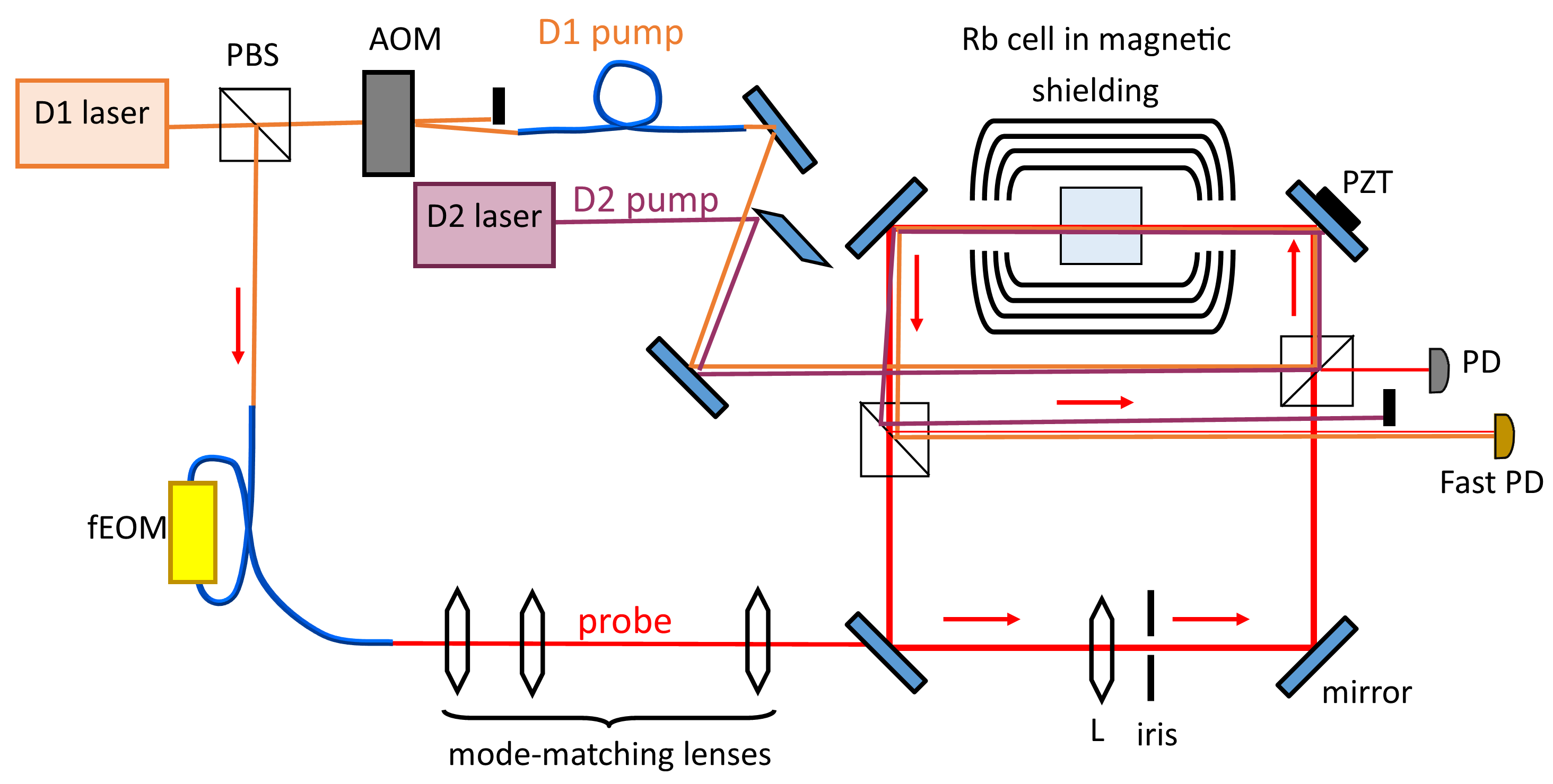 |
A simplified schematic of the experimental setup is shown in Fig. 2. The current version of the experiment uses two external cavity diode lasers, each of which are equipped with a saturation-absorption-spectroscopy frequency reference, not shown in the figure. One laser, tuned to the optical transition of 87Rb, serves as the pump field, and the second laser, operating at the 87Rb line ( nm) is used to generate both pump and probe optical fields. For that purpose the laser output is split with a polarizing beam splitter (PBS). The transmitted beam is coupled into an single-mode optical fiber, and phase-modulated using a fiber-coupled electro-optical modulator (fEOM) operating at the microwave frequency of GHz. The power of the modulation was chosen such that the amplitude of the unmodulated carrier field was suppressed to approximately of its original value, and approximately 40% of the power was transferred to each of the first modulation sidebands. The output of the fiber modulator is coupled into the ring-cavity, with additional lenses to ensure maximum coupling into the fundamental TEM00 spatial cavity mode.
The two pump fields are combined using a sharp-edge mirror at a small angle of approximately mrad and enter the cavity through the input polarizing beam-splitter. They are linearly-polarized and perpendicular to the intra-cavity probe field polarization. The direct output of the nm laser (properly attenuated and linearly polarized) is used for the pump. The laser beam at the cell is oval-shaped, with minimum and maximum diameters of mm and mm. The frequency of the pump is shifted down by MHz using an acousto-optical modulator (AOM) with respect to the nm laser output to ensure that the frequency difference between this optical field and the probe field () GHz is close to the 87Rb ground state hyperfine splitting. This additional shift in optical frequency of the pump helps to eliminate a parasitic interference between this field and the carrier frequency component of the fEOM output (of the original laser wavelength), which partially leaks into the ring cavity. After passing through a single-mode optical fiber, the pump field is collimated into a Gaussian beam with a waist of mm FWHM.
The ring cavity consists of four flat mirrors ( % reflection), arranged in a square configuration, and a convex lens (focal length cm). The total length of the cavity is cm. One of the mirrors is mounted on a piezo-electric device (PZT), which allows sweeping the cavity length to observe its resonances or locking the cavity resonance frequency to the frequency of the circulating optical field using a feedback loop.
For the current experiments we used a cylindrical Pyrex Rb vapor cell (diameter 22 mm; length 25 mm), containing isotopically enriched 87Rb and 5 torr of Ne buffer gas, placed inside a three-layer magnetic shielding to mitigate the effects of any stray magnetic field. The cell is heated to , and the value of the column density was extracted by fitting the weak-probe absorption curve. To realize the four-wave mixing configuration for the probe optical field inside the ring cavity, we have also added two polarizing beam splitters inside the cavity such that the circulating probe field is transmitted, but the two pump optical fields are reflected to overlap with the probe field on the PBS, and then reflected off at the output PBS. After introduction of these optical elements the cavity finesse is approximately for light frequencies not on resonance with the Rb atoms, which means that the power of the circulating optical field reduced to approximately of its initial value after one round-trip inside the cavity [22]:
| (1) |
The free spectral range of the cavity (FSR) was measured to be MHz. Since the different frequencies outputted by the EOM are not simultaneously resonant with the cavity, we are able to couple in only the probe field, without need for additional spectral filtering.
We used a small residual reflection of the probe optical field at the input PBS to monitor its power. To measure its spectral properties we directed the pump field and the probe field, reflected off the output cavity PBS, into a fast photodetector, and monitored their beatnote amplitude and frequency using a spectrum analyzer.
3 Experimental measurements of the probe field amplification and generation
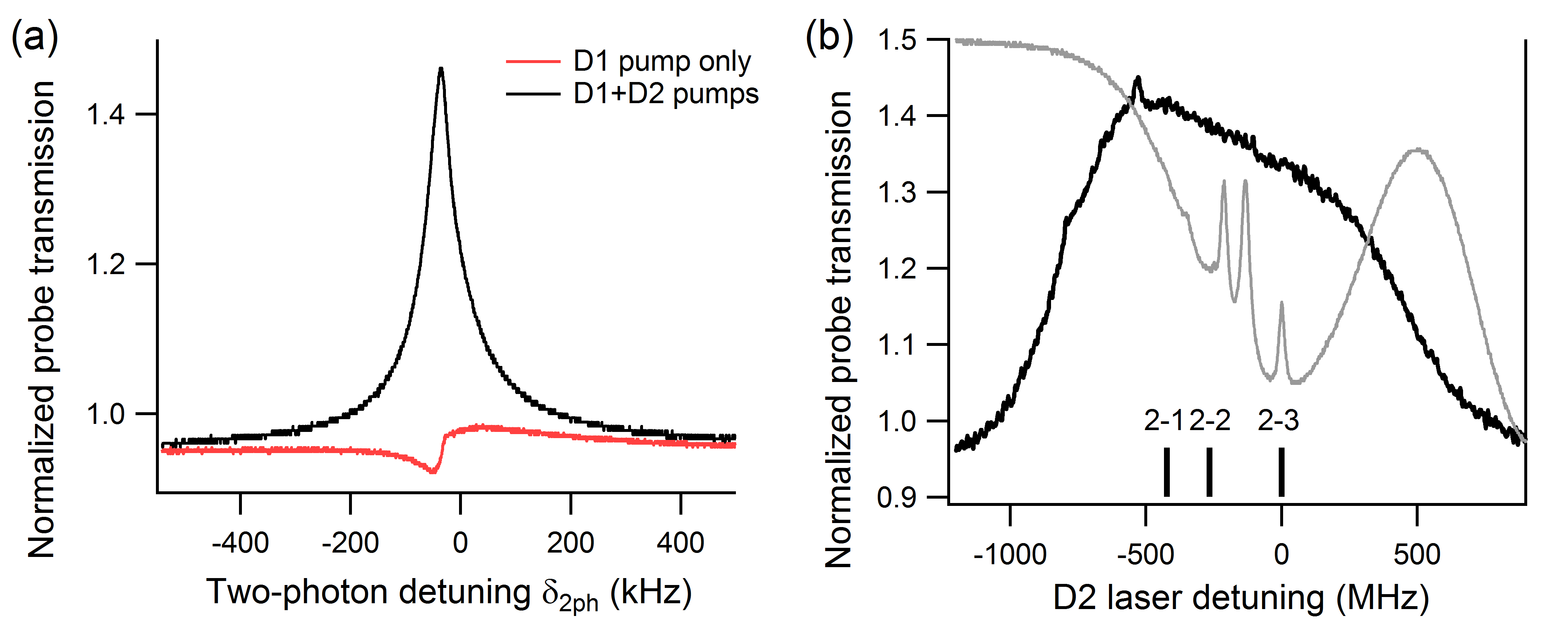
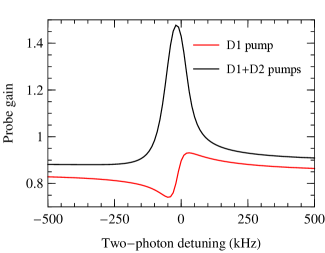
Before placing the atomic medium in the ring cavity we confirmed that it is possible to achieve probe field amplification in our realization of the N interaction scheme. In particular, if only the pump field was present, completing a single link, we observe the usual EIT-like variation in the probe transmission with the two-photon detuning between the probe and the pump fields. Fig. 3(a) demonstrates the two-photon resonance for the laser detuning at the slope of the Doppler-broadened optical transition, chosen to match the experimental conditions in which we observed maximum FWM gain later. Because of this relatively large laser detuning, the shape of the two-photon resonance was asymmetric [23]. We have maintained this detuning value of the laser from the optical transition frequency for all reported measurements. However, it is possible that the value of the laser detuning corresponding to the maximum gain depends on the temperature of the cell, i.e., the resonant absorption can overcome gain produced in the four-wave mixing process. Dependence of FWM on atomic density will be a subject of further studies.
In the presence of the second pump field, forming the N-scheme, the probe field exhibited a strong symmetric amplification peak, with maximum gain of . We also measured the variation of the probe gain with the laser detuning, as shown in Fig. 3(b). While amplification was observed in a relatively wide range of laser frequencies, the highest gain occurred around transitions, for which the selection rules allow the four-wave mixing process.
 |
We observed even stronger amplification when the probe field circulated inside the ring cavity. Fig. 4(a) shows that when both pump fields were tuned to the four-wave mixing gain conditions, the probe field output increased dramatically. While we expect such amplification to be accompanied by the generation of the fourth optical field on the optical transition (as we observed in previous studies [12]), we were not able to directly detect it here, as the experimental arrangement does not favor its amplification. Indeed, this field has to propagate along the pump field to satisfy the phase-matching conditions, and thus it cannot circulate inside the ring cavity due to the small misalignment of the pump field.
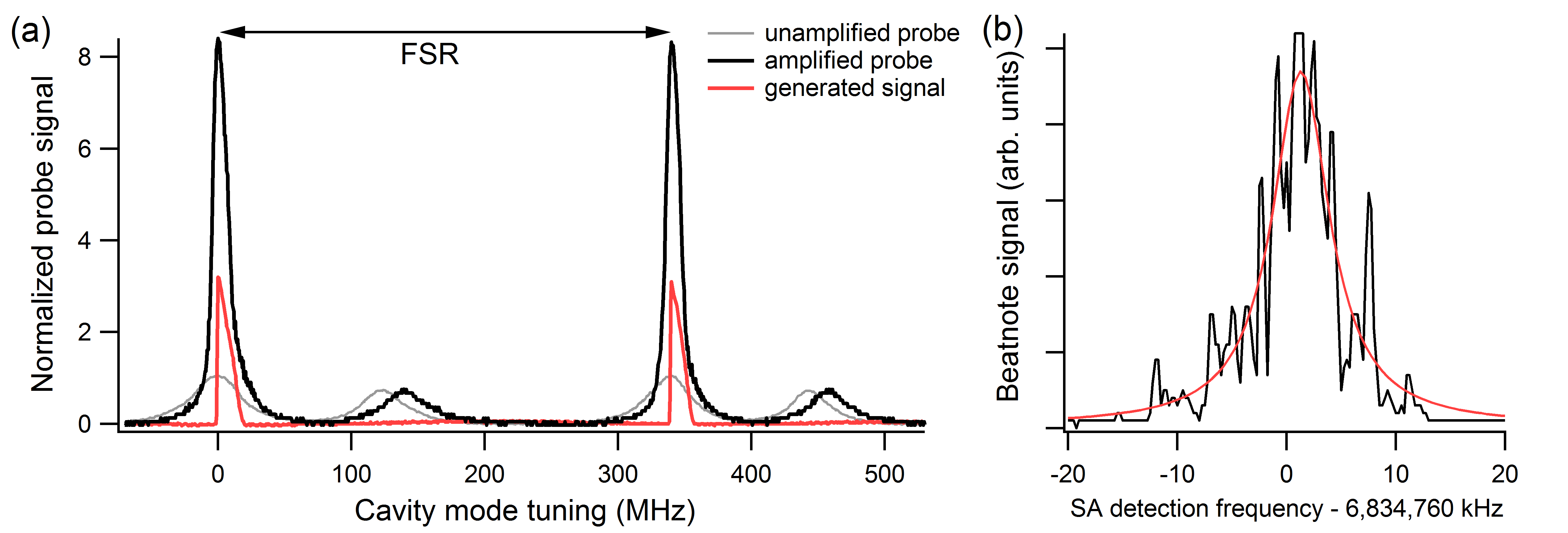 |
When the input probe field blocked, so that only the two pump fields interacted with the atoms, we observed the generation of an optical field at the probe frequency, circulating inside the cavity. The analysis of the beatnote between this new generated field and the pump field indicated that these two fields are phase-coherent. An example of such a beatnote shown in Fig. 4(b) gives a rough width estimate of kHz (FWHM), determined predominantly by the acoustic instabilities of the cavity. The instantaneous width seems to be limited only by the spectrum-analyzer resolution.
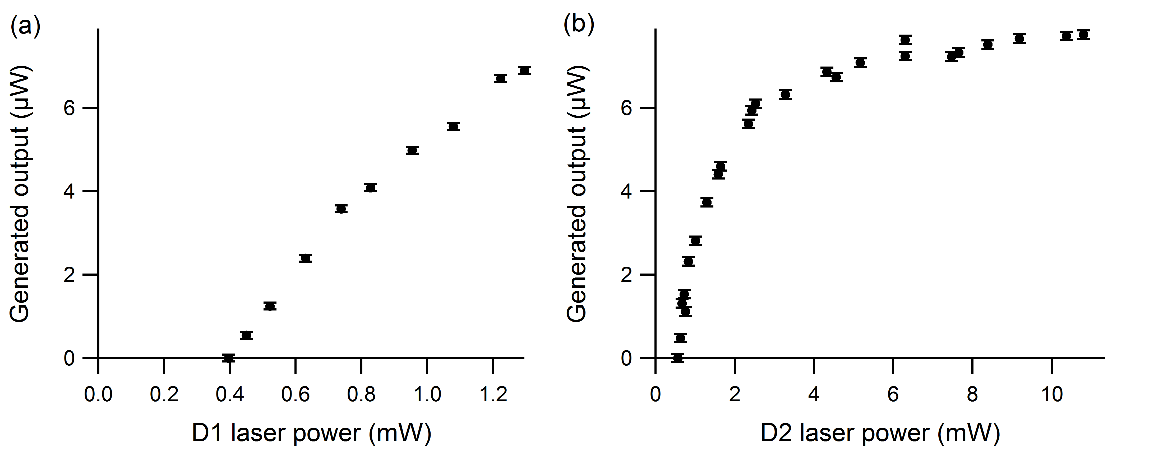
The amplitude of the generated field displayed a typical threshold behavior as a function of the power of either of the pump beams, as shown in Fig. 5. The values of the thresholds also depended on the laser detunings and relative alignment of the pump fields. The fundamental cavity mode had the lowest threshold values, which is not surprising, since this was the mode the seeded probe field is coupled to, and thus the pump laser parameters are optimized to maximize the gain in that mode. However, at higher pump powers, higher spatial modes were generated as well. The threshold values for those modes were typically twice as high as that for the fundamental mode, but they depended strongly on the cavity alignment and pump laser detunings. After the initial fast increase of the generated field amplitude above the threshold, we observed a clear saturation, for which further increase in laser power did not produce significant growth in the probe field power.
 |
4 Density-matrix simulation of the probe field propagation
A density-matrix calculation was performed to model the propagation of the pump and probe fields through the atomic medium, both for the case of a single pass of the probe light through the medium, and the case in which the medium is placed in a ring cavity. The atoms were modeled as a four-level system as shown in Fig. 1. In analogy to the Rb system, we refer to the pump fields as the and pumps, even though the intensities and detunings of these fields were adjusted to account for the differences between 87Rb and the simplified model system. The semiclassical density-matrix evolution equations, written as a function of distance along the light propagation direction, take into account the optical fields, spontaneous decay from the upper states, transit relaxation, and pressure broadening. In order to take into account Doppler broadening, the longitudinal velocity distribution is divided into velocity groups, with a set of evolution equations written for each velocity group. These equations are coupled to the one-dimensional wave equation for the four optical fields, with the coupling for a particular optical frequency proportional to the total atomic polarization at that frequency, obtained by summing over all velocity groups.
In the steady state, the equations reduce to a set of differential algebraic equations in the spatial variable that can be solved as an initial-value problem to find the change in optical fields upon a single pass through the medium. Figure 6 shows the single-pass probe gain as a function of two-photon detuning with D1 pump only and with both D1 and D2 pump, for comparison with the experimental results of Fig. 3. The following input parameters were chosen to approximately match the parameters for 87Rb and the experimental setup: excited state natural widths MHz, pressure broadening MHz, Doppler width 330 MHz, optical fields’ wavelengths 795 nm (for the optical transition) and 780 nm (for the optical transition), and optical path length through the atomic medium 2.5 cm. The remaining experimental parameters were adjusted by hand to improve the agreement with the experimental measurements shown in Fig. 3: transit relaxation rate kHz, D1 pump detuning -800 MHz, D2 pump detuning 0 MHz, D1 pump intensity 3 mW/cm2, D2 pump intensity 3 mW/cm2, probe intensity 0.5 mW/cm2, and atomic density cm-3 (0.2 times the experimental value; this scaling was necessary because the four-level model system has intrinsically larger optical coupling constants than Rb). These values were used for all of the following results except where noted.
The propagation dynamics of the probe field inside the ring cavity is characterized by two main parameters: the single-pass complex gain through the atomic medium , which accounts for the effect of the interactions with the atomic medium, and was calculated according to the method described above; and the complex gain for one round trip of the probe light through the empty cavity that describes all intracavity losses and the accumulated optical phase shift. (We use the term “gain” to describe , even though its absolute value is always less than unity.) The generated probe amplitude and frequency are then obtained by numerically solving for the condition of stable single-mode oscillation, namely, that the total complex gain for one round-trip inside the cavity is equal to unity: .
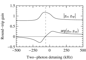
Figure 7 shows the circulating generated probe intensity in the cavity as a function of D1 and D2 pump intensities. The parameters are as given above, except that the D2 pump intensity is fixed at 6 mW/cm2 in Fig. 7(a) and the the D1 pump intensity is fixed at 6 mW/cm2 in Fig. 7(b). The magnitude of the round-trip empty cavity gain was determined from the experimental finesse measurements in Eq. 1. In order to allow lasing of the probe field, the complex phase of was adjusted (corresponding to tuning the cavity resonance frequency) so that the total round-trip complex phase shift crosses zero within the gain feature (Fig. 8).
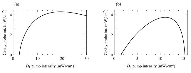
The calculated dependences of the generated probe intensity on the intensities of each pump optical field (as the other pump intensity is held fixed), shown in Fig. 7, demonstrate clear generation thresholds followed by a rapid increase in the generated probe power, similar to the experimental observations. For higher pump powers, however, the probe intensity levels off and then falls. The beginning of this saturation was also observed in Fig. 5(b) as a function of pump power, while the limited available power in the laser prevented us from reaching this regime in Fig. 5(a). However, neither laser was powerful enough to observe the reduction of the generated probe power in the limit of high powers (although such fall-off was observed experimentally in case of different laser detunings).
The calculation indicates that this behavior is a result of the saturation and decrease of the single-pass gain as a function of pump intensity. Even though the magnitude of the single-pass gain does not fall below unity, it does eventually fall below the threshold needed to overcome the cavity losses and allow oscillation. The saturation effect does not occur if both of the pump intensities are increased simultaneously—evidently the correct balance of pump intensities is required for optimal probe gain in the medium.
5 Delay/advance measurement
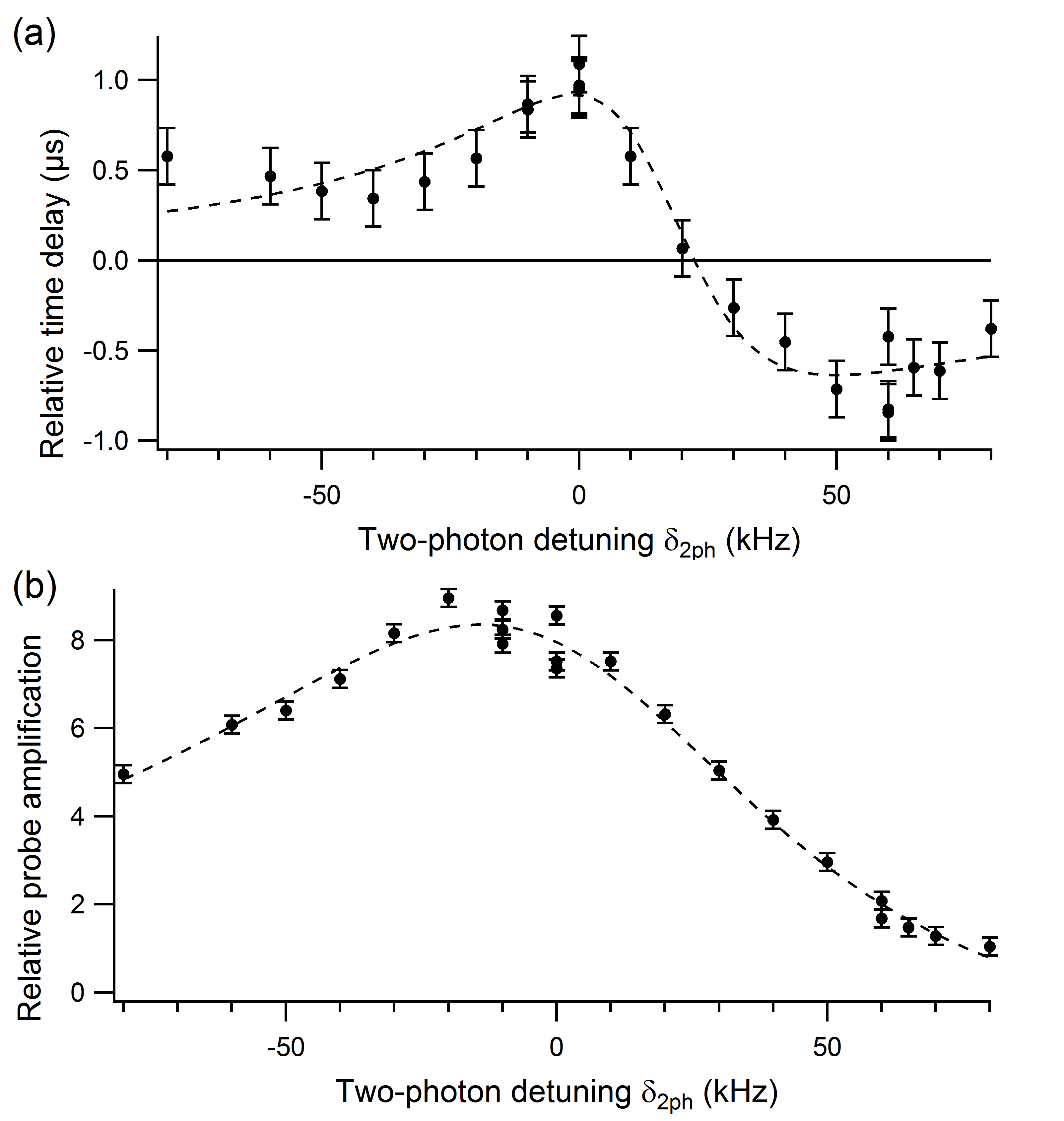 |
Next, we evaluated the dispersive properties of the system by sending an amplitude-modulated probe field and measuring its relative time shift after the cavity. For these measurements we actively locked the cavity on a probe-transmission resonance, and in addition introduced a sinusoidal amplitude modulation at frequency . We have verified that with careful choice of modulation parameters this modulation does not affect the cavity lock. For these measurements we chose the powers of the two pump fields such that only amplification and no generation occurs in the cavity. The output probe signal maintained the sinusoidal shape, and thus we determined the relative time shift from changes in phase fitting parameter. The reference phase is measured when both pump fields are blocked, and the probe field is far-detuned from the atomic resonance. Fig. 9 shows the variation of the observed time shifts as we tuned the probe two-photon detuning through the gain profile. Near the maximum we observed a relative delay. However, for increasing negative detunings this delay smoothly changed into advancement, indicating superluminal propagation.
6 Cavity pulling
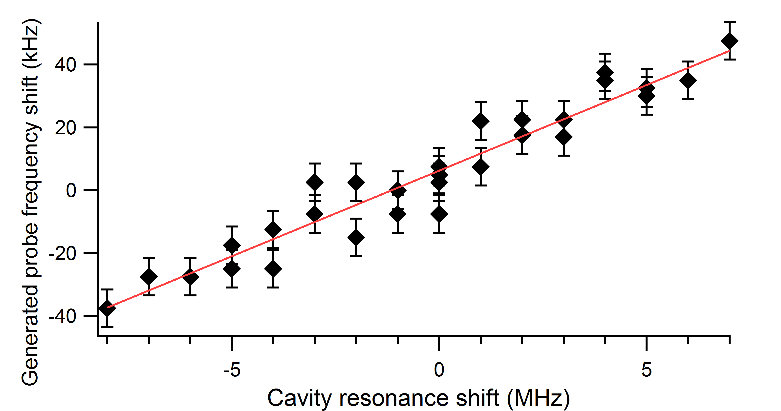
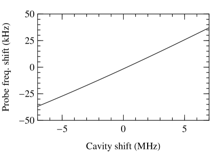
It is important to point out that the spectral bandwidth of the FWM gain ( kHz) is significantly narrower than the cavity transmission resonance ( MHz), and thus our current experiment cannot be considered a realization of the original theoretical proposal [1]. Under such conditions we expect that the frequency and the width of the probe field, generated inside a cavity, will be dominated by the spectral properties of the laser field. Nevertheless, we observed that the change in the cavity length produced a measurable effect on the generated probe frequency, as shown in Fig. 10.
For these measurements we have injected into a cavity a “+1” modulation sideband detuned by approximately MHz such that its maximum transmission occurred at the same cavity length as the probe field generation. Since this field was sufficiently weak and detuned far from any two-photon resonances, its presence in the cavity did not affect FWM process. At the same time, locking the cavity resonance to the transmission peak of this seeded field allowed us to change the cavity length in highly controllable manner, and observe a systematic frequency shift of the generated probe field as the cavity was swept through the transmission resonance. A numerical calculation of the cavity pulling was also performed, using the techniques described in Sec. 4, and it is in good agreement with the experimental results, as seen in Fig. 10(b).
|
7 Conclusions
In conclusion, we have analyzed the propagation of a weak resonant probe through a medium of four-level atoms in an N-scheme with allowed four-wave mixing generation, and found it to be a promising candidate for the realization of tunable “slow-to-fast” light with no absorption. This is particularly interesting for the experimental investigation of potential techniques for the enhancement of optical-gyroscope performance.
8 Acknowledgments
The authors thank Frank A. Narducci and Jon Davis for useful discussions, and Gleb Romanov for helping with the experiment. This research was supported by the Naval Air Warfare Center STTR program, contract N68335-13-C-0227.
References
- [1] M. S. Shahriar, G. S. Pati, R. Tripathi, V. Gopal, M. Messall, and K. Salit, “Ultrahigh enhancement in absolute and relative rotation sensing using fast and slow light,” Phys. Rev. A 75(5), 053807 (2007).
- [2] G. S. Pati, M. Salit, K. Salit, and M. S. Shahriar, “Demonstration of a tunable-bandwidth white-light interferometer using anomalous dispersion in atomic vapor,” Phys. Rev. Lett. 99 (2007).
- [3] G. S. Pati, M. Salit, K. Salit, and M. S. Shahriar, “Demonstration of displacement-measurement-sensitivity proportional to inverse group index of intra-cavity medium in a ring resonator,” Opt. Commun. 281(19), 4931–4935 (2008).
- [4] C. Ciminelli, C. E. Campanella, F. Dell’Olio, and M. N. Armenise, “Fast light generation through velocity manipulation in two vertically-stacked ring resonators,” Opt. Express 18, 2973–2986 (2010).
- [5] M. Salit, K. Salit, and P. Bauhahn, “Prospects for enhancement of ring laser gyroscopes using gaseous media,” Opt. Express 19, 25312–25319 (2011).
- [6] O. Kotlicki, J. Scheuer, and M. S. Shahriar, “Theoretical study on Brillouin fiber laser sensor based on white light cavity,” Opt. Express 20, 28234–28248 (2012).
- [7] R. W. Boyd and D. J. Gauthier, “Chapter 6 “slow” and “fast” light,” in Progress in Optics, E. Wolf, Ed., Progress in Optics 43, 497 – 530, Elsevier (2002).
- [8] H. N. Yum, M. Salit, J. Yablon, K. Salit, Y. Wang, and M. S. Shahriar, “Superluminal ring laser for hypersensitive sensing,” Opt. Express 18, 17658–17665 (2010).
- [9] J. Zhang, X. Wei, G. Hernandez, and Y. Zhu, “White-light cavity based on coherent raman scattering via normal modes of a coupled cavity-and-atom system,” Phys. Rev. A 81, 033804 (2010).
- [10] O. Kotlicki, J. Scheuer, and M. Shahriar, “Theoretical study on brillouin fiber laser sensor based on white light cavity,” Opt. Express 20, 28234–28248 (2012).
- [11] N. B. Phillips, I. Novikova, E. E. Mikhailov, D. Budker, and S. M. Rochester, “Controllable steep dispersion with gain in a four-level N-scheme with four-wave mixing,” J. Mod. Opt. 60, 64–72 (2013).
- [12] I. Novikova, E. E. Mikhailov, L. Stagg, D. Budker, and S. M. Rochester, “Tunable lossless slow and fast light in a four-level N-system,” Proc. SPIE: Advances in Slow and Fast Light 8636, 86360C (2013).
- [13] M. D. Lukin, “Colloquium: Trapping and manipulating photon states in atomic ensembles,” Rev. Mod. Phys. 75(2), 457 (2003).
- [14] M. D. Lukin, A. B. Matsko, M. Fleischhauer, and M. O. Scully, “Quantum noise and correlations in resonantly enhanced wave mixing based on atomic coherence,” Phys. Rev. Lett. 82(9), 1847 (1999).
- [15] E. E. Mikhailov, Y. V. Rostovtsev, and G. R. Welch, “Experimental study of Stokes fields linewidth in resonant four-wave mixing in Rb vapour,” J. Mod. Opt. 49(14), 2535–2542 (2002).
- [16] N. B. Phillips, A. V. Gorshkov, and I. Novikova, “Slow light propagation and amplification via electromagnetically induced transparency and four-wave mixing in an optically dense atomic vapor,” J. Mod. Opt. 56(18), 1916–1925 (2009).
- [17] T. Hong, A. V. Gorshkov, D. Patterson, A. S. Zibrov, J. M. Doyle, M. D. Lukin, and M. G. Prentiss, “Realization of coherent optically dense media via buffer-gas cooling,” Phys. Rev. A 79, 013806 (2009).
- [18] N. B. Phillips, A. V. Gorshkov, and I. Novikova, “Light storage in an optically thick atomic ensemble under conditions of electromagnetically induced transparency and four-wave mixing,” Phys. Rev. A 83, 063823 (2011).
- [19] R. Fleischhaker and J. Evers, “Four-wave mixing enhanced white-light cavity,” Phys. Rev. A 78, 051802 (2008).
- [20] T. Abi-Salloum, S. Meiselman, J. P. Davis, and F. A. Narducci, “Four-level ‘N-scheme’ in bare and quasi-dressed states pictures,” J. Mod. Opt. 56(18), 1926–1932 (2009).
- [21] R. T. Glasser, U. Vogl, and P. D. Lett, “Stimulated generation of superluminal light pulses via four-wave mixing,” (2012). arXiv:1204.0810.
- [22] A. E. Siegman, Lasers, University Science Books (1986).
- [23] E. E. Mikhailov, V. A. Sautenkov, I. Novikova, and G. R. Welch, “Large negative and positive delay of optical pulses in coherently prepared dense Rb vapor with buffer gas,” Phys. Rev. A 69(6), 063808 (2004).