Low-Power Distance Bounding
Abstract
A distance bounding system guarantees an upper bound on the physical distance between a verifier and a prover. However, in contrast to a conventional wireless communication system, distance bounding systems introduce tight requirements on the processing delay at the prover and require high distance measurement precision making their practical realization challenging. Prior proposals of distance bounding systems focused primarily on building provers with minimal processing delays but did not consider the power limitations of provers and verifiers. However, in a wide range of applications (e.g., physical access control), provers are expected to be fully or semi passive introducing additional constraints on the design and implementation of distance bounding systems.
In this work, we propose a new physical layer scheme for distance bounding and leverage this scheme to implement a distance bounding system with a low-power prover. Our physical layer combines frequency modulated continuous wave (FMCW) and backscatter communication. The use of backscatter communication enables low power consumption at the prover which is critical for a number of distance bounding applications. By using the FMCW-based physical layer, we further decouple the physical distance estimation from the processing delay at the prover, thereby enabling the realization of the majority of distance bounding protocols developed in prior art. We evaluate our system under various attack scenarios and show that it offers strong security guarantees against distance, mafia and terrorist frauds. Additionally, we validate the communication and distance measurement characteristics of our system through simulations and experiments and show that it is well suited for short-range physical access control and payment applications.
1 Introduction
The widespread deployment of wireless systems that use location and proximity to provide services has led to the advent of many radio frequency based localization technologies [21]. Today, these systems are used in a broad set of scenarios including people and asset tracking, emergency and rescue support [11] and access control [14, 26]. Given the safety and security implications of the above mentioned applications, it is important to ensure the security of the location estimate and data used in these systems.
Distance bounding enables the secure measurement of an upper bound on the physical distance between two devices, a verifier and a prover, even if the prover is untrusted and tried to reduce the measured distance. Distance bounding was initially introduced in the context of wired systems [3] and later a number of distance bounding protocols [37, 38, 16, 28, 22, 29, 4, 5, 24, 23, 33] were designed for wireless systems. In-order to compute the upper bound on the physical distance, distance bounding relies on the measurement of the round-trip time between a transmitted challenge and a received response. Successful execution of a distance bounding protocol relies on two main assumptions: (i) Precise distance bound estimate and (ii) Low processing time at the prover to compute the response. Precise measurement of the distance depends largely on the physical characteristics of the RF signal and the time-of-arrival estimation technique implemented in the system. The time taken by the prover to process the challenge (i.e., demodulate, compute and transmit the response) depends on the chosen processing function and is critical to prevent distance modification attacks such as distance fraud [3] or mafia fraud [10]. Reducing this processing time is therefore critical, such that the prover cannot modify its processing time arbitrarily and pretend to be closer to the verifier. Some prior work on prover design focused on using analog or hybrid digital-analog processing in order to reduce the prover processing time to few nanoseconds [28, 25]. Those designs focus primarily on the prover architecture without much consideration for the physical characteristics (modulation scheme, bandwidth, encoding, bit periods etc.) of the radio communication signals, which form a critical part of a distance bounding system.
Another line of work considered the implementation of distance bounding using ultra-wide band (UWB) signals with well defined physical-layer characteristics. Tippenhauer [36] implemented a distance bounding system with a prover processing delay of approximately . This limits the distance modification by an untrusted prover to maximum . While the proposed distance bounding implementation was well specified, it is not clear whether the prover processing time can be reduced to a few nanoseconds and whether such prover designs can be made practical for power sensitive applications (e.g., RFID localization, proximity-based electronic tokens for access control and mobile payments).
The realization of low power provers for distance bounding is very important for the development of practical distance bounding systems in many of today’s applications. For example, RFID technology is used in a number of applications ranging from identification and tracking of commodity goods, physical access control, animal husbandry tracking, automatic toll collection systems, electronic passports and payment systems. Prior research has revealed that the use of RFID proximity to provide access control is vulnerable to mafia-fraud (relay) attacks (e.g., PKES systems [12], NFC phones [13], Google Wallet [30]). The ability to realize distance bounding protocols for passive or semi-passive RFID devices (or tags) would prevent the majority of relay attack scenarios.
Our physical layer scheme uses the frequency modulated continuous wave (FMCW) for distance estimation and On-Off Keying technique for data communication. We show that due to the inherent nature of FMCW, the distance estimation phase is only loosely coupled to the challenge processing at the prover i.e., the distance estimation is independent of the processing delay at the prover while keeping the security guarantees of the system intact. This enables logical layer implementation of any distance bounding protocol proposed in prior art. Our proposed system architecture offers complete protection against distance fraud attacks where a dishonest, but trusted prover tries to cheat on the distance by processing the challenges faster. An attacker does not gain any distance advantage by replying earlier or processing the challenges faster. In addition, we provide maximum distance reduction estimates for a strong attacker who is capable of detecting challenges earlier and relaying them to a trusted prover.
In this work, we propose a new distance bounding system designed for short-range, low-power applications. Specifically, we make the following contributions.
-
•
We propose and evaluate a new physical layer scheme specifically designed for the realization of distance bounding systems.
-
•
Leveraging this physical layer scheme, we design a prover that can potentially be integrated into passive and semi-passive RFID tags, thus enabling distance bounding for power constrained applications.
-
•
We analyze our system under distance, mafia and terrorist fraud attacks and show how our system resists these attacks.
-
•
We evaluate our system through simulations and experimentally validate its processing delay, power consumption and ranging precision.
The remainder of the paper is organized as follows. In Section 2 we introduce distance bounding and briefly discuss the existing distance bounding systems and their current limitations. In Section 3, we provide the essentials of FMCW and describe our physical layer scheme for distance bounding. We analyze our system against the known distance, mafia and terrorist fraud attacks in Section 4 and experimentally evaluate the design in Section 5. Finally, we discuss future work and conclude the paper in Section 6.
2 Distance Bounding
2.1 Background
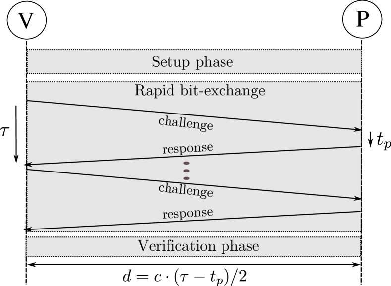
The goal of a distance bounding system is that a verifier establishes an upper bound on its physical distance to a prover. Distance bounding protocols follow a specific procedure which typically includes a setup, rapid-bit exchange and verification phases (Figure 1). In the setup phase, the verifier and the prover agree or commit to specific information that will be used in the next protocol phases. In the rapid-bit exchange phase, the verifier challenges the prover with a number of single-bit challenges to which the prover replies with single-bit responses. The verifier measures the round-trip times of these challenge-reply pairs in order to estimate its upper distance bound to the prover. The distance between the verifier and the prover is calculated using the equation , where is the speed of light (), is the round-trip time elapsed and is the processing delay at the prover before responding to the challenge. The verification phase is used for confirmation and authentication. It should be noted that depending on the protocol construction the verification phase may not be required.
The security of distance bounding protocols is traditionally evaluated by analyzing their resilience against three types of attacks: Distance Fraud, Mafia Fraud and Terrorist Fraud attacks. Figure 2 illustrates graphically these attack scenarios and the entities involved. In a distance fraud attack, an untrusted prover tries to shorten the distance measured by the verifier. Since the round-trip time includes the processing delay, an untrusted prover can reduce the distance measured by either sending its replies before receiving the challenges or by computing the responses faster. There is no external attacker involved in this attack.
Mafia fraud attacks, also called relay attacks, were first described by Desmedt [10]. In this type of attack, both the prover and verifier are honest and trusted. An external attacker attempts to shorten the distance measured between the prover and the verifier by relaying the communications between the entities. Distance bounding protocols prevent relay attacks due to the fact that the time taken to relay the challenges and responses will only further increase the distance bound estimate. However, it is important to keep the variance of the prover’s processing time to a minimum to ensure high security guarantees. If the time taken by the prover to process challenges varies significantly between challenges, the verifier has to account for the high variance in its distance estimation. Depending on the amount of variance to be accounted for, an attacker can reduce the distance by relaying communications between the prover and the verifier.

Finally, in terrorist fraud attacks, an untrusted prover collaborates with an external attacker to convince the verifier that he is closer than he really is. All countermeasures to terrorist fraud make the assumption that the untrusted prover does not reveal his long-term (private or secret) key to the external attacker which he collaborates with.
Recently, another type of attack on distance bounding protocols called the distance hijacking attack was proposed [7]. The authors give a real world example of a dishonest prover with a stolen smartcard gaining access to a secure facility; though he is not within the required proximity. The attacker exploits a honest prover’s presence by hijacking its rapid bit-exchange phase with the verifier. A system’s resilience to distance hijacking depends on the higher level protocol implementation and is independent of the physical-layer. Therefore, in this work we do not address distance hijacking attacks.
2.2 Distance Bounding Implementations
A number of distance bounding protocols were proposed following the work of Brands and Chaum [3]. These protocols provide resilience against one or all of the above mentioned attacks. However, the security of these protocols was mostly analyzed based on information theoretic proofs without considering physical layer attacks. For example, a protocol is said to be resilient against distance fraud attacks if the response bits are dependent on the challenge bits, i.e., the prover cannot respond before actually receiving the challenge. As described previously, a prover’s distance is measured based on some physical layer parameter such as received signal strength or round trip times. Therefore, in practice, the security of distance bounding protocols also depends on the actual physical layer design and implementation of the distance bounding system.
For instance, an untrusted prover can use specialized or modified hardware to compute a response faster than the delay expected by the verifier to estimate the distance. It is important to note that a speedup of translates to a distance gain of approximately . An attacker can also reduce the distance between the verifier and prover by detecting or demodulating challenges before receiving them completely or late committing a response as shown by Clulow et al. [6]. In order to address these attacks specific to the physical layer, the focus shifted towards secure physical layer design of distance bounding systems. Below we summarize the existing physical layer related designs available in the open literature. Table 1 compares these designs based on the power requirement, prover processing delay, resilience to distance, mafia, and terrorist frauds, and the feasibility to implement any distance bounding protocol.
[b] Implementation Attack Resilience Compatible Protocols Power Reqb DF (processing delay)a MF TF Tippenhauer [36] () Any High Hancke [15] () HKP [16] High CRCS [28]c () CRCS High Ranganathan [25]c () HKP based [19, 38, 29] High Our Work (d ) Any Low
-
a
A prover processing delay enables a maximum distance reduction of by a dishonest prover.
-
b
Power consumption at the prover.
-
c
Focused primarily on reducing the prover’s processing delay and used frequency switching to communicate data.
-
d
The use of slots enables us to decouple the distance estimation from the processing delay.
Initial distance bounding implementations [31, 27] proposed the use of both radio frequency and ultrasound. The verifier that wants to securely verify the location claim of a prover transmits a challenge using RF and the prover responds back using ultrasound. Based on the time-of-arrival of the ultrasound packet, the location claim ‘’ of the prover and the propagation time of radio and ultrasound signals in air, the verifier estimates the prover’s distance ‘’. If ‘’ is larger than the claimed distance ‘’, then the verifier rejects the prover’s location claim. The authors reasoned out that the use of RF communication in both directions would make the prover’s processing delay very large making the system unusable. One of the main problems with these systems is that an untrusted prover or an external attacker with a proxy node in the verifier’s region of interest can take advantage of this. By using radio frequency as a wormhole channel to echo the response back to the verifier, the attacker can reduce the round-trip-time and hence the distance estimate. Hence, it became essential to develop new methods to reduce the prover’s complexity and processing delay.
Hancke’s Distance Bounding Channel
Hancke and Kuhn [16] introduced one of the first distance bounding protocols suitable for computationally constrained devices such as RFID with a specific prover design. Subsequently, Hancke [15] further extended this work with a UWB communication channel. In the proposed channel, the verifier (here, the RFID reader) embeds the challenge bits as ultra-wideband pulses in addition to the transmitted carrier signal. These pulses are transmitted with a delay after every rising edge of the carrier signal. This delay is known apriori to both the verifier and the prover. The presence or absence of the pulse indicates whether the challenge bit is ’’ or ’’. The prototype implementation resulted in distance bounds for near field RFID up to for trusted provers and in case of untrusted provers. Several challenges exist in implementing this design. First, since the communication link includes both low-frequency carrier and the ultra-wideband pulses, the RFID tag receiver architecture complexity increases drastically. Second, the ambiguity in distance still depends on the processing delay of the prover. Hence, an untrusted prover with access to faster hardware can reduce the processing delay thereby cheating on the distance estimated by the verifier.
Tippenhauer’s UWB Distance Bounding System
Tippenhauer [36] designed and implemented a distance bounding system with focus on optimizing the rapid bit-exchange phase. Due to the ranging precision and resilience to multipath effects, an impulse radio ultra-wideband (IR-UWB) physical layer was used for communication. IR-UWB systems communicate data using short pulses which are typically long. Range estimation is based on the time elapsed between transmitting a challenge pulse and receiving a corresponding response. In any distance bounding protocol the rapid bit-exchange phase is the core and the final distance estimation is based on the exact timing of these challenge and response pulses. Since the design primarily focused on the fast rapid bit-exchange phase, any distance bounding protocol can be implemented and deployed using this system. The processing delay at the prover depends on the protocol adopted e.g., the XOR processing function used in the prototype implementation resulted in an overall delay of . However, the narrow IR-UWB pulses utilize a large bandwidth () which require both the prover and the verifier to be equipped with high sampling rate ADCs and DACs to receive and transmit IR-UWB pulses respectively. Such high sampling rate ADCs and DACs consume significant power (typically around ) making it infeasible for applications where power consumption at the prover needs to be low (order of few mW or W).
Rasmussen’s Challenge Reflection with Channel Selection (CRCS)
The CRCS [28] scheme reduced the prover’s processing delay to by eliminating the need for interpreting the challenge during the rapid-bit exchange phase. In this implementation, the challenges are reflected back by the prover on different frequency channels. Given that the incoming challenge is not interpreted during the time-critical phase, the majority of state-of-art distance bounding protocols (e.g., Brands-Chaum, Hancke-Kuhn) cannot be realized using this scheme. In addition, the lack of challenge demodulation made this scheme vulnerable to terrorist fraud attacks. For example, as shown in [25] an untrusted prover can pre-calculate the responses (since they are independent of the challenge signal in CRCS) and forward them to a colluding attacker located near the verifier. The colluding attacker can then successfully execute the rapid-bit exchange phase with the verifier. Based on the CRCS scheme, Ranganathan et al. [25] proposed a hybrid analog-digital prover design that is resilient to terrorist fraud attacks with a prover processing delay of approximately . This design can be used to implement all distance bounding protocols that follow the Hancke-Kuhn protocol construction i.e., the response is selected from one or more registers based on the challenge. Both works focused on minimizing the challenge processing delay at the prover through architectural modifications with very few details on the physical layer characteristics of the radio frequency signal which plays a critical role in ranging precision and data communication. In addition, the absence of challenge interpretation during the rapid-bit exchange phase makes the system vulnerable to simple response replay attacks. In order to prevent such attacks, the prover needs to demodulate, store and communicate the challenges back to the verifier during the final verification phase of the protocol. This increases the complexity making it challenging to realize low power provers.
We summarize and compare the aforementioned implementations in Table 1. With the exception of [36], all the implementations have limitations on the higher layer distance bounding protocols that can be implemented. In all these systems, the resilience to distance fraud attacks depends on the processing delay at the prover. For example, in the case of CRCS [28] where the prover has a processing delay of , an untrusted prover can cheat on its distance to a maximum . Distance bounding protocols inherently protect these systems against conventional amplify and forward relay attacks. However, their resilience to a stronger attacker capable of detecting challenges earlier than a conventional receiver (more details discussed in Section 4.2) is dependent on the physical properties of the transmitted information (e.g., symbol duration, type of modulation scheme used). In addition, the physical layer scheme also affects the ranging precision, complexity of prover design and therefore its power consumption. The complex design and strict hardware requirements (e.g., ADC and DAC requirements) makes them unsuitable for power sensitive applications. In this work, we fill this void by proposing a complete physical layer scheme, specifically designed for distance bounding that can be leveraged to build low power provers.
3 FMCW based Distance Bounding
3.1 FMCW Basics
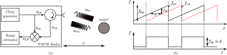
Monotone (or single frequency) radars transmit pulses of short duration and measure distance based on the round-trip time of the received pulse reflected off the target. Such radars are more susceptible to channel interference. In Frequency Modulated Continuous Wave (FMCW) radar [34], chirp signals [2] are used to determine range and velocity of a target. Figure 3(a) illustrates the basic building blocks of a conventional FMCW radar system. The radar base station transmits a chirp signal () which gets reflected off the target object back to the base station. The reflected signal () is then mixed with the transmitted signal at that instant to produce a “beat frequency”. The beat frequency () is proportional to the round-trip time () taken to receive the reflected chirp signal; thereby able to measure distance to the target object.
The transmitted chirp signal is mathematically represented as shown below.
| (1) |
where is the frequency sweep function given by Equation (2) and is the starting value of the frequency sweep. is the rate of frequency sweep and is a quotient of the length of the chirp signal and the total bandwidth swept i.e., .
| (2) |
The transmitted chirp is reflected off the target object at distance and is received back at the radar base station as .
| (3) |
The frequency of the reflected signal can be represented in terms of the instantaneous frequency of the transmitted chirp as
| (4) |
Mixing the signals and results in an intermediate frequency signal which consists of frequency components and . The difference component is termed as the “beat frequency” given by
| (5) |
Simplifying and representing in terms of distance , i.e., , where is the speed of light (), distance of the target object from the radar base station is estimated using Equation (7).
| (6) |
| (7) |
Maximum measurable distance and range resolution are two important performance metrics of any ranging system. Maximum measurable distance is the largest value of distance that can be measured using a particular ranging system. In a FMCW radar, this is dependent on the time duration of the chirp signal and is given by . Range resolution is the minimum change in distance that can be detected and is proportional to the time resolution of . In other words, is inversely proportional to the total bandwidth swept by the chirp and is mathematically represented as shown in Equation (8).
| (8) |
3.2 Data Modulation for Distance Bounding

Conventional radar systems do not require any kind of data transmission. However, in distance bounding protocols the communicating entities (verifier and prover) exchange challenges and responses during the rapid bit-exchange phase. This requires data to be modulated over conventional FMCW radar signals. In this work, we modulate the challenge and response bits over the FMCW chirp signal using On-Off Keying (OOK). Mathematically, the transmitted signal with OOK modulation can be represented as
| (9) |
where is the data-bit period given by ( is the length of the data packet to be transmitted) and represents the payload.
The distance bound is estimated similar to conventional FMCW radar systems based on the “beat frequency” as shown in Equation (7). We describe the system design in more detail in the next sections.
3.3 Verifier and Prover Design
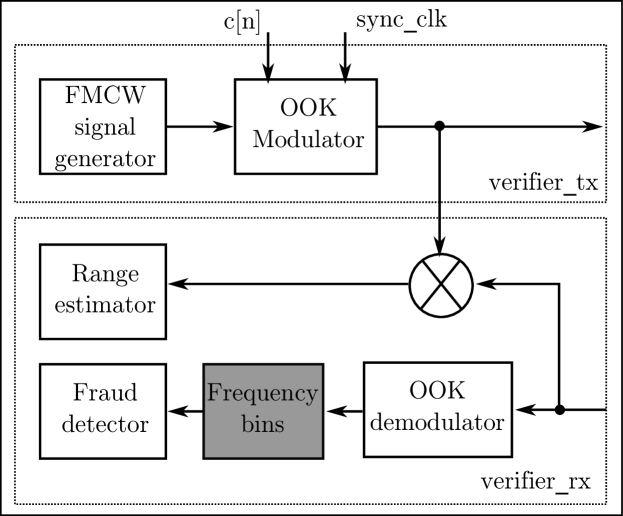
Figure 5 shows the high-level components present in our system architecture. We focus on the rapid-bit exchange phase since it is, implementation- and power-wise the most demanding phase of the protocol execution.
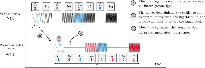
The verifier’s transmitter () module consists of an FMCW signal generator and an OOK modulator. The FMCW signal generator generates a chirp signal of time duration . The entire chirp signal is divided into slots, each with time duration . The prover synchronizes to these slots using a preamble that is transmitted by the verifier. The verifier divides the slots into challenge and reply slots such that every challenge slot is followed by a response slot. During the challenge slots, the verifier modulates the challenge bits using OOK modulation and continues to transmit the unmodulated chirp signal during the response slot (Figure 4). The response slots are used by the prover to transmit its response back to the verifier.
When the prover receives the challenge signal from the verifier, it processes it through two circuits: (i) reflecting and (ii) response circuits. The reflecting circuit as its name suggests simply reflects the received signal after optionally amplifying it (for increased range). The response circuit is responsible for challenge demodulation and computation of the prover’s response using a processing function. The output of the processing function is then modulated on top of the reflected signal. We note that any processing function proposed for distance bounding in prior art can be used here. Therefore, our proposed physical layer is independent of the logic-level protocols. The computed response is OOK modulated over the chirp signal during the corresponding response slot. Like in conventional passive RFID tags, the prover can simply load modulate its responses back to the verifier. It is important to note that the prover continues to reflect back the received signal while simultaneously demodulating the challenges and computing its response. The propagation delay of the response computation path is one of the factors that determines the slot duration . However, has limited effect on the system’s overall security as explained in Section 4.
The verifier’s receiver module receives the reflected signal that contains the reflected challenges and the prover’s modulated responses and estimates its distance to the prover. The verifier generates an intermediate signal by mixing with as shown in Figure 5 and computes a distance bound by analyzing the frequency components of as expressed in Equations (6) and (7). In addition, the verifier demodulates and checks the correctness of the prover’s responses. It is important to note that, in a majority of scenarios, the verifier does not have strict power limitations and therefore the demodulator and signal processing at the verifier can be implemented as efficiently as possible.
3.4 Realization of Low Power Provers
| Detector | Operating current | Response time |
|---|---|---|
| LTC5536 | ||
| AD8313 | ||
| AD8314 |
RFID technology has become ubiquitous in a number of security-critical ranging applications (e.g., commodity goods identification and tracking, physical access control, automatic toll collection and electronic payment systems). Prior works [12, 13, 30] showed the vulnerability of RFID based proximity systems to simple mafia fraud (relay) attacks. One of the main challenges in enabling distance bounding protocols for these applications is the tag’s strict power constraints. Passive RFID tags do not have any built-in power sources and derive power by rectifying the received interrogating signal from the reader. As a result, they are less complex, work only at short ranges and are incapable of transmitting data on their own. Passive tags communicate with the reader by modifying the signal received from the reader. Semi-passive tags have a built-in power source to, for example, amplify the response signal, but still cannot transmit data independently without the presence of a reader’s interrogating signal.
The proposed FMCW based physical layer scheme would enable realization of distance bounding systems, with low power consumption at the tag (prover). Our prover design in Section 3.3 can be implemented in passive and semi-passive RFID tags operating in the ISM 2.4 GHz and 5.8 GHz bands using 80 MHz and 150 MHz 111In theory, 80 MHz gives distance resolution of 1.87 m, 150 MHz of 99 cm bandwidth respectively to achieve high distance precision. Since our system targets short-range distance measurement applications (less than ), the use of spectrum [18] is also possible. Given that these tags (e.g., [8, 9, 32]) already have backscatter communication capability to send back the distance bounding response, the only addition would be to incorporate the response computing function which can be as simple as an inverter or an XOR operation. There are already several commercially available radio frequency energy detectors that operate in the above mentioned frequency bands with integrated comparators and amplifiers. In addition, the response time of these detectors are well under and consume less than of current. Table 2 lists a few commercially available detectors with the above mentioned specifications that can be integrated into state-of-art RFID tags for an additional power consumption of .
Furthermore, it should be noted that passive FMCW-based RFID tags have already been deployed for asset localization in industrial settings [1]. In-order to increase the maximum range that can be measured, FMCW-based semi-passive RFID tag designs were also explored. For example, the pulsed reflector design of [39] can measure distances with a ranging precision of and a low power consumption of . In [35], the authors present a circuit design for BiCMOS integrated circuits with a power consumption of . Thus, using our proposed physical layer scheme it is indeed possible to realize provers that consume low power suitable for deployment in power-constrained environments.
4 Security Analysis
In this section, we analyze the security of our proposed system under the distance, mafia and terrorist fraud attacks.
4.1 Distance Fraud
In a distance fraud, an untrusted prover claims to be at a distance closer than the actual one. In conventional secure ranging systems, an untrusted prover can shorten the measured distance either by modifying its internal processing delay time or by replying before receiving the complete challenge signal. In the former, the prover implements an improved hardware to process the challenges faster than the “processing delay” accounted in the distance estimation at the verifier. In the latter case, the prover early detects the challenge signal, computes and transmits back the response (sometimes later than required also referred to as “late commit” [6]) resulting in faster processing thereby reducing the distance estimated by the verifier.
In our system, the dishonest prover does not gain any distance advantage by speeding up response computation as distance is estimated solely based on the beat frequency created by mixing the reflected signal with the transmitted FMCW signal. The slot assignment to challenge and response bits forces the prover to wait until the challenge is reflected before modulating the response on the response slot. Early modulation would corrupt the challenge signal thereby being detected at the verifier during the response validation phase. Also, the prover does not gain any distance by executing such an early response attack as the distance estimation based on FMCW is completely decoupled from the data response at the prover.
The same reasoning holds for an untrusted prover who early detects the challenge signal, computes and late commits the response without any colluding entity in close proximity to the verifier. Irrespective of how fast the prover detects and processes the challenge, unless the prover reflects the signal from close proximity to the verifier, he will not be able to cheat on the measured distance.
4.2 Mafia Fraud
Mafia fraud attacks are also called relay attacks and were first described by Desmedt [10]. The attacker is an external entity who attempts to shorten the distance estimated by the verifier by relaying communications between the verifier and the honest prover. There are two ways in which an attacker can carry out a mafia fraud at the physical layer: (i) Amplify and forward (ii) Early-detect and late commit of data symbols.
Amplify and forward: In this method, the attacker simply amplifies and relays communication between the verifier and the prover. The attacker does not modify any physical layer characteristic of the symbol. Such a method is insufficient for an attacker since the effective distance computed would still be the actual distance between the trusted prover and the verifier.
Early-detect and late-commit: Clulow et al. [6] introduced the early-detect and late-commit attacks where a successful attacker early detects (ED) the symbols from the verifier and late commits (LC) those signals from the prover back to the verifier. The feasibility of ED and LC attacks on RFID was demonstrated in [17]. Here, we analyze the resilience of the proposed OOK-FMCW physical layer against ED and LC attacks. In order to successfully execute the attack, the attacker must do the following: (i) early-detect the challenge from the verifier, (ii) communicate it to prover, (iii) early-detect the response from the prover and finally (iv) late commit a value back to the verifier. For the analysis, lets consider one challenge and response slot. Assuming that the verifier requires at least 222Assuming an energy detection based demodulator at the verifier with the threshold set to half the maximum symbol energy. This can vary depending on the type of receiver used to demodulate data. of the symbol to demodulate correctly, an attacker has time to respond. Within this time, the attacker must perform the above mentioned operations. If is the time necessary for the attacker to reliably early-detect the challenge from the verifier and the response from the prover, is the delay at the attacker hardware for amplifying and relaying, the time remaining for the attacker to relay communications is given by,
| (10) |
Since the prover is trusted, the response will be available only after the challenge slot time period i.e., . Therefore,
| (11) |
Therefore the maximum distance an attacker can cheat on can be expressed as,
| (12) |
It is important to note that Equation (12) holds good even in the scenario where an external attacker (in close proximity to the verifier) reflects the challenge signal back to the verifier resulting in a beat frequency corresponding to the attacker’s distance from the verifier. However, for a successful attack, the attacker still has to modulate the response after the challenge slot period . This time constraint forces the attacker to early detect, relay and late commit the challenge and response bits as described previously and hence the maximum distance gained remains unchanged.
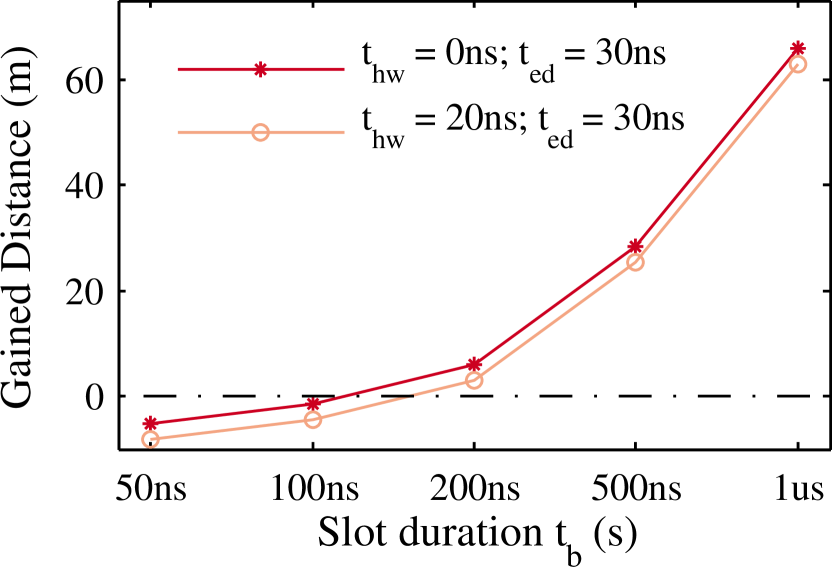
In Figure 6, we give an intuition by substituting nominal values for and . In a real world scenario, the values will depend on various characteristics of the attacker hardware (e.g., filter order, ADC delays, signal group delay, algorithm used to early-detect etc.). Since is selected based on the delay of the challenge processing function at the prover, it can be observed that even for an attacker with ideal hardware (), it is impossible to reduce the distance against a system with prover processing delay of .
Mafia fraud detector:
The linearly increasing frequency characteristic of the chirp signal makes it feasible to detect mafia fraud attacks by analyzing the frequency components at specific time intervals. This temporal knowledge of the signal enables us to assign every challenge and response to one or more frequency bins. Each frequency bin contains spectral energy values for a range of contiguous frequencies. Specifically, it is possible to estimate the range of frequencies a particular challenge or response bit will occupy given a slot period , starting sweep frequency and chirp duration . We divide each challenge and response slot into frequency bins. For a successful attack, the attacker must ED and LC every challenge and response. A late commit on a symbol would result in incorrect bin values and this would appear consistently throughout the chirp sweep bandwidth. Thus, by analyzing the frequency bins for expected spectral energy values, a late commit attack can be detected. It is safe to assume that the possibility of incorrect spectral values consistently at specific frequency intervals due to just channel fading effects is negligible, and such an effect could have occurred due to a LC attack. The late commit detection can be improved by dividing dividing each slot into more frequency bins i.e., increasing . The modified verifier with the frequency bin based mafia fraud detection module is shown in Figure 7.
4.3 Terrorist Fraud
In Terrorist fraud attacks, a dishonest prover collaborates with an external attacker to convince the verifier that he is closer than he really is. The prover will help the attacker with information as long as it does not reveal the prover’s long term secret. Terrorist fraud resilient protocols [38, 19, 29] bind the prover’s long term secret to the nonces that are exchanged in the protocol. This prevents the prover from revealing the nonces to the attacker without disclosing its long term secret. Since our proposed physical layer is independent of the high-level protocol, the system security depends on the distance bounding protocol implemented above the physical layer.
Special case of terrorist fraud: Consider the scenario where a nearby external attacker simply reflects the interrogating OOK-FMCW signals back to the verifier, while simultaneously relaying the signals to the distant prover. The untrusted prover colludes with the attacker and helps him authenticate (by providing the responses) without revealing its long term secret key. The tasks needed to be executed by the external attacker and the untrusted prover is similar to that of a mafia fraud attacker as described in Section 4.2. However in this setting, the prover colludes with the attacker and therefore communicates the response as soon as possible. Thus, the attacker is not constrained by the additional time (Equation (11)) and the maximum possible distance that the attacker can cheat is same as that expressed in Equation (10).
5 System Evaluation
In this section, we evaluate our proposed distance bounding system using both simulations and experiments. Through simulations, we analyze the bit error rate and ranging precision due to the on-off keying over FMCW. Then, we experimentally validate our prover’s processing delay and ranging precision using a prototype.
5.1 Simulation Model and Analysis
The preliminary analysis through simulations were done using Matlab. The OOK-FMCW signal is generated by mixing a binary data signal with a chirp. The duration of a single chirp () was fixed at with the initial sweep frequency set to . The physical layer parameters such as the chirp bandwidth and bit-period (duration of each slot) is made configurable based on the analysis performed. The generated OOK signal is passed through an additive white Gaussian noise (AWGN) channel. The signal to noise ratio (SNR) of the channel is varied depending on the analysis performed. We model the receiver as two submodules: (i) Energy detector for demodulating data sent over OOK-FMCW and (ii) FMCW-based distance measurement module. For the energy detection, the threshold value to distinguish the bits ‘0’s and ‘1’s is set at a value lower than the maximum energy estimated for a ‘1’ bit under no noise conditions. The signal processing for distance estimation is implemented following the theory described in Section 3.1.

BER and Ranging Precision
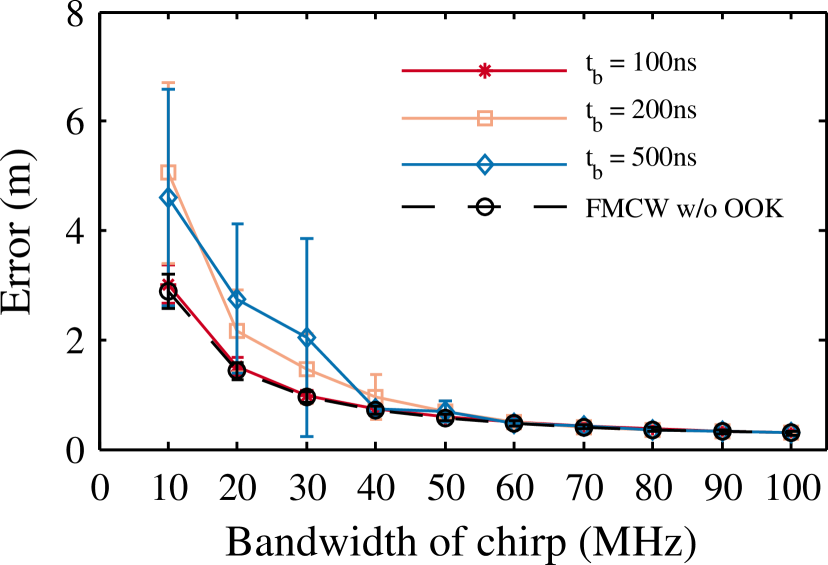
First, we determine the minimum SNR required to reliably communicate data i.e., challenges and responses with the proposed physical layer scheme. In our simulations we vary the SNR from – keeping the slot length a constant. It is observed that for SNR greater than , we were able to demodulate the bits with a BER of . Next, we analyze the effect on ranging precision due to the OOK modulation over conventional FMCW radar. In addition to , SNR is set to a constant . For a specific , the error in distance measured is determined for various values of . The error is a mean value obtained by measuring different distances within the possible maximum measurable distance . The simulations are repeated for and the results are shown in Figure 8. It is observed that the challenge slot period has limited effect on the distance measurement precision for signals with bandwidth greater than . We note that, even at lower bandwidths, the observed precision would still be suitable for a wide range of ranging applications. Alternatively, we could use amplitude shift keying e.g., a signal with low amplitude can represent a ’0’ bit as against absence of the signal itself (as in OOK). We use the above results of our preliminary simulations to build and evaluate our prover through real experiments.
5.2 Experimental Setup
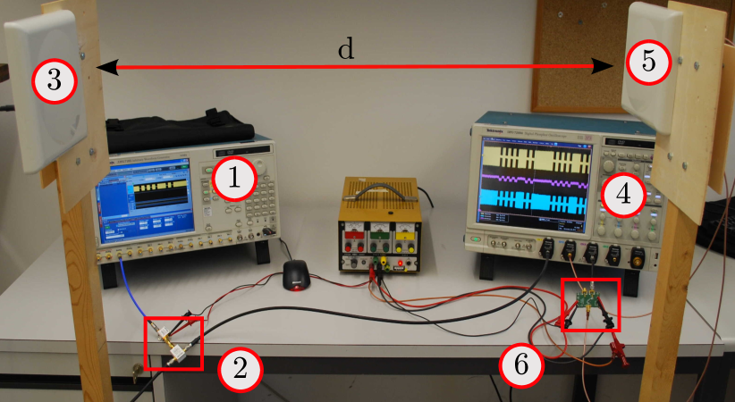
In this section, we describe the experimental setup (Figure 9) used to evaluate our proposed distance bounding system. Our experiments primarily focuses on the two critical parameters of any distance bounding system: (i) Challenge processing delay and (ii) Ranging precision.
A picture of our experimental setup is shown in Figure 11. The transmitter consists of an arbitrary waveform generator (AWG) capable of generating signals at a sampling rate of , a radio frequency amplifier and a directional planar antenna. The OOK-FMCW signals are generated using Matlab as described in Section 5.1 and loaded into the AWG. The OOK-FMCW signals are amplified and transmitted using a planar antenna. At the receiver, the signals are captured using a planar antenna similar to the one used at the transmitter. The received signal is recorded on a digital storage oscilloscope (DSO). In addition, the received signal is input to the challenge demodulator circuit [20] which essentially is a Schottky RF peak detector with programmable gain and a high speed comparator. The output of the demodulator circuit is also observed on the oscilloscope. We evaluate our system for different configurations of OOK-FMCW signals with the initial sweep frequency set to . The various physical characteristics of the signals used in the evaluations are listed in Table 3.
| Parameter | Value |
|---|---|
| Sweep bandwidth | , |
| Slot period | , |
| Modulation index | , |
5.3 Experimental Results
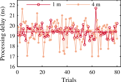
Challenge Processing Delay : The challenge processing delay plays an important role in deciding the duration of the challenge and response slots . In our experimental setup, is the time delay for the energy detector to demodulate the received OOK-FMCW challenge signal and switch the output of the comparator. For accurate time delay measurements, the signals are pre-processed by applying Hilbert transform and passing it through a median filter (to preserve the rising and falling edges while reducing noise). Figure 10 shows the response times observed at the receiver over a number of trials. The processing delay was measured with the receiver placed at and away from the transmitter. The medial delay observed was about and remained largely unaffected due to distance from the transmitter. Hence, the value of can be further reduced to about (including fall-time) without affecting the decoding of challenge bits. Additionally, it is observed that the values show greater variance with distance due to the variations in the received signal’s energy between trials.
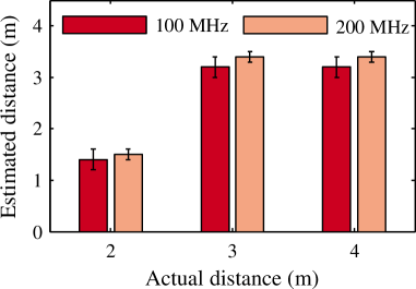
Ranging Precision: In order to evaluate the ranging precision, we placed the receiver at distances , and from the transmitter. The distance bound is calculated using standard FMCW techniques as described in Section 3.1 and the results are plotted in Figure 10. It can be observed that our prototype has a ranging precision of less than a meter for the evaluated short distances. Due to the limitations of our experimental setup, we could not measure longer distances. A combination of factors such as range resolution (and hence signal bandwidth), channel multipaths and the receiver sampling rate affect the precision of a ranging system. Other physical characteristics of the OOK-FMCW signal such as modulation index, bit (slot) period and duration of chirp had no effect on the precision of the ranging system.
6 Conclusion
In this work, we proposed and analyzed a new physical layer scheme designed specifically for enabling distance bounding for short-range, low-power application scenarios. In this proposal, we combined on-off keying and frequency modulated continuous wave to design a prover that can potentially be integrated into passive and semi-passive RFID tags. OOK-FMCW guarantees the distance bound independent of the processing delay at the prover; irrespective of the distance bounding protocol implemented. Through our security analysis, we showed that our system is resilient against distance, mafia and terrorist fraud attacks. For slot durations less than , we showed that our system is fully resilient against an attacker capable of early detection and late commit of the challenge and response bits. We experimentally validated our distance bounding system’s ranging precision and challenge processing delay. In addition, our experiments reveal that it is indeed feasible to realize low-power provers that can process challenges as fast as .
As part of future work, we intend to build a complete prototype to fully evaluate our system’s power and performance characteristics. In addition, the feasibility of using other modulation methods (e.g., ASK, PSK) over FMCW remains to be explored. The nominal values for the security relevant parameters such as the time required to early detect and late commit under these modulation schemes also needs to be investigated further.
References
- [1] Symeo - Absolute Positioning. www.symeo.de.
- [2] Berni, A. J., and Gregg, W. D. On the Utility of Chirp Modulation for Digital Signaling. IEEE Transactions on Communications 21, 6 (June 1973), 748–751.
- [3] Brands, S., and Chaum, D. Distance-bounding protocols. In Workshop on the theory and application of cryptographic techniques on Advances in cryptology (May 1993), EUROCRYPT ’93, Springer-Verlag New York, Inc., pp. 344–359.
- [4] Bussard, L., and Bagga, W. Distance-Bounding Proof of Knowledge to Avoid Real-Time Attacks. In Proceedings of 20th International Conference on Security and Privacy in the Age of Ubiquitous Computing (May 2005), pp. 223–238.
- [5] Capkun, S., Buttyán, L., and Hubaux, J.-P. Sector: secure tracking of node encounters in multi-hop wireless networks. In Workshop on Security of Ad Hoc and Sensor Networks (SASN) (Oct. 2003), ACM, pp. 21–32.
- [6] Clulow, J., Hancke, G., Kuhn, M., and Moore, T. So Near and Yet So Far: Distance-Bounding Attacks in Wireless Networks. In Proceedings of the 3rd European Workshop on Security and Privacy in Ad-Hoc and Sensor Networks, Lecture Notes in Computer Science. Springer, Sept. 2006, pp. 83–97.
- [7] Cremers, C., Rasmussen, K. B., Schmidt, B., and Capkun, S. Distance Hijacking Attacks on Distance Bounding Protocols. In Proceedings of the 33rd IEEE Symposium on Security and Privacy (May 2012).
- [8] Dardari, D., and D’Errico, R. Passive ultrawide bandwidth rfid. In Global Telecommunications Conference, 2008. IEEE GLOBECOM 2008. IEEE (2008), IEEE, pp. 1–6.
- [9] D’Errico, R., Bottazzi, M., Natali, F., Savioli, E., Bartoletti, S., Conti, A., Dardari, D., Decarli, N., Guidi, F., Dehmas, F., et al. An uwb-uhf semi-passive rfid system for localization and tracking applications. In RFID-Technologies and Applications (RFID-TA), 2012 IEEE International Conference on (2012), IEEE, pp. 18–23.
- [10] Desmedt, Y., Goutier, C., and Bengio, S. Special Uses and Abuses of the Fiat-Shamir Passport Protocol. In CRYPTO (Aug. 1987), pp. 21–39.
- [11] Fischer, C., and Gellersen, H. Location and Navigation Support for Emergency Responders: A Survey. IEEE Pervasive Computing 9 (Jan. 2010), 38–47.
- [12] Francillon, A., Danev, B., and Ĉapkun, S. Relay Attacks on Passive Keyless Entry and Start Systems in Modern Cars. In Proceedings of the 18th Annual Network and Distributed System Security Symposium (Feb. 2011), The Internet Society.
- [13] Francis, L., Hancke, G., Mayes, K., and Markantonakis, K. On the security issues of NFC enabled mobile phones. International Journal of Internet Technology and Secured Transactions 2 (Dec. 2010).
- [14] Gupta, S. K. S., Mukherjee, T., Venkatasubramanian, K., and Taylor, T. B. Proximity Based Access Control in Smart-Emergency Departments. In Proceedings of the 4th Annual IEEE International Conference on Pervasive Computing and Communications Workshops (Mar. 2006), pp. 512–516.
- [15] Hancke, G. P. Design of a secure distance-bounding channel for RFID. J. Netw. Comput. Appl. 34, 3 (May 2011), 877–887.
- [16] Hancke, G. P., and Kuhn, M. G. An RFID distance bounding protocol. In Proceedings of the 1st International Conference on Security and Privacy for Emerging Areas in Communication Networks (Sept. 2005), pp. 67–73.
- [17] Hancke, G. P., and Kuhn, M. G. Attacks on time-of-flight Distance Bounding Channels. In Proceedings of the 1st ACM Conference on Wireless Network Security (Apr. 2008), ACM, pp. 194–202.
- [18] Hirt, W. The european uwb radio regulatory and standards framework: Overview and implications. In Ultra-Wideband, 2007. ICUWB 2007. IEEE International Conference on (2007), IEEE, pp. 733–738.
- [19] Kim, C. H., Avoine, G., Koeune, F., Standaert, F.-X., and Pereira, O. The swiss-knife RFID distance bounding protocol. In Information Security and Cryptology — ICISC 2008. Springer-Verlag, Berlin, Heidelberg, Dec. 2009, pp. 98–115.
- [20] Linear Technology. LTC5564 - UltraFast 7ns Response Time 15GHz RF Power Detector with Comparator. http://www.linear.com/docs/30075.
- [21] Liu, H., Darabi, H., Banerjee, P., and Liu, J. Survey of Wireless Indoor Positioning Techniques and Systems. IEEE Transactions on Systems, Man, and Cybernetics 37, 6 (Nov. 2007), 1067–1080.
- [22] Munilla, J., and Peinado, A. Distance bounding protocols for RFID enhanced by using void-challenges and analysis in noisy channels. ACM Journal on Wireless Communications and Mobile Computing 8, 9 (Nov. 2008), 1227–1232.
- [23] Peris-Lopez, P., Castro, J. C. H., Estévez-Tapiador, J. M., Palomar, E., and van der Lubbe, J. C. A. Cryptographic puzzles and distance-bounding protocols: Practical tools for RFID security. In IEEE International Conference on RFID (Apr. 2010), pp. 45–52.
- [24] Peris-Lopez, P., Castro, J. C. H., Estévez-Tapiador, J. M., and van der Lubbe, J. C. A. Shedding Some Light on RFID Distance Bounding Protocols and Terrorist Attacks. CoRR abs/0906.4618 (2009).
- [25] Ranganathan, A., Tippenhauer, N. O., Škorić, B., Singelée, D., and Capkun, S. Design and Implementation of a Terrorist Fraud Resilient Distance Bounding System. In Computer Security – ESORICS 2012, vol. 7459 of Lecture Notes in Computer Science. Springer, Sept. 2012, pp. 415–432.
- [26] Rasmussen, K. B., Castelluccia, C., Heydt-Benjamin, T. S., and Čapkun, S. Proximity-based Access Control for Implantable Medical Devices. In Proceedings of the 16th ACM conference on Computer and Communications Security (Nov. 2009), ACM, pp. 410–419.
- [27] Rasmussen, K. B., and Čapkun, S. Location Privacy of Distance Bounding Protocols. In Proceedings of the 15th ACM conference on Computer and Communications Security (Oct. 2008), pp. 149–160.
- [28] Rasmussen, K. B., and Čapkun, S. Realization of RF Distance Bounding. In Proceedings of the 19th USENIX Security Symposium (Aug. 2010), pp. 389–402.
- [29] Reid, J., Nieto, J. M. G., Tang, T., and Senadji, B. Detecting relay attacks with timing-based protocols. In Proceedings of the 2nd ACM symposium on Information, computer and communications security (Mar. 2007), pp. 204–213.
- [30] Roland, M. Applying recent secure element relay attack scenarios to the real world: Google wallet relay attack. Computing Research Repository abs/1209.0875 (2012).
- [31] Sastry, N., Shankar, U., and Wagner, D. Secure verification of location claims. In Proceedings of the 2nd ACM workshop on Wireless Security (New York, NY, USA, Sept. 2003), ACM, pp. 1–10.
- [32] Seetharam, D., and Fletcher, R. Battery-powered rfid. In 1st ACM Workshop on Convergence of RFID and Wireless Sensor Networks and their Applications (2007).
- [33] Singelée, D., and Preneel, B. Distance bounding in noisy environments. In Proceedings of the 4th European conference on Security and privacy in ad-hoc and sensor networks (Berlin, Heidelberg, July 2007), Springer-Verlag, pp. 101–115.
- [34] Stove, A. G. Linear FMCW radar techniques. Radar and Signal Processing, IEE Proceedings F 139, 5 (Oct. 1992), 343–350.
- [35] Strobel, A., and Ellinger, F. An active pulsed reflector circuit for fmcw radar application based on the switched injection-locked oscillator principle. In Semiconductor Conference Dresden (SCD), 2011 (Sept. 2011), pp. 1–4.
- [36] Tippenhauer, N. O. Physical-Layer Security Aspects of Wireless Localization. PhD thesis, ETH Zurich, Switzerland, 2012.
- [37] Tippenhauer, N. O., and Čapkun, S. ID-based Secure Distance Bounding and Localization. In Proceedings of the 14th European Conference on Research in Computer Security (Berlin, Heidelberg, Sept. 2009), Springer-Verlag, pp. 621–636.
- [38] Tu, Y.-J., and Piramuthu, S. RFID Distance Bounding Protocols. In First International EURASIP Workshop on RFID Technology (Vienna, Austria, Sept. 2007).
- [39] Wehrli, S., Gierlich, R., Hüttner, J., Barras, D., Ellinger, F., and Jäckel, H. Integrated Active Pulsed Reflector for an Indoor Local Positioning System. IEEE Transactions on Microwave Theory and Techniques 58, 2 (Feb. 2010), 267–276.