Enhancing User Experience for Multi-Screen Social TV Streaming over Wireless Networks
Abstract
Recently, multi-screen cloud social TV is invented to transform TV into social experience. People watching the same content on social TV may come from different locations, while freely interact with each other through text, image, audio and video. This crucial virtual living-room experience adds social aspects into existing performance metrics. In this paper, we parse social TV user experience into three elements (i.e., inter-user delay, video quality of experience (QoE), and resource efficiency), and provide a joint analytical framework to enhance user experience. Specifically, we propose a cloud-based optimal playback rate allocation scheme to maximize the overall QoE while upper bounding inter-user delay. Experiment results show that our algorithm achieves near-optimal tradeoff between inter-user delay and video quality, and demonstrates resilient performance even under very fast wireless channel fading.
I Introduction
Cloud social TV is transforming the traditional TV watching habit into a social networking experience. As users’ media consuming behaviors are migrating from TV screens to smartphones and tablets [1], multi-screen cloud social TV [2, 3, 4, 5] was proposed to re-invent traditional TV experience through interactive social features. Specifically, its virtual living-room experience brings interactivity among peer viewers [6], such that various forms of information (i.e., text, image, audio and video) are exchanged in response to the ongoing video content.
However, delivering good user experience over heterogenous networks poses tremendous challenge in the real deployment of cloud social TV. First, due to the inherent nature of stochastic wireless network, the video quality deteriorates under deep fading wireless channels. Second, the inter-user delay accumulates as the video plays, which can affect the social interaction experience. Imagine that Peter and his friend Cathy are in a social TV “room” watching the same soccer game. Peter excitedly texts to Cathy about a goal he just witnessed, which turns out to be “spoiler” to Cathy who is suffering from long delay. Moreover, the quality of service should be guaranteed within affordable operational cost, i.e., without incurring high operational cost of cloud resource. Therefore, an effective design of cloud social TV should be in place to enhance user experience by simultaneously addressing the above three issues.
Existing works in this domain separately considered either the enhancement of video quality of experience (QoE) or the reduction of operation cost of multimedia services, but none of them jointly consider the three-element user experience of cloud social TV. In [7, 8], adaptive video playback rate at the end users is introduced to optimize perceived video quality under rapidly changing bandwidth. Both [9] and [10] considered the QoE-driven cache management at the server, while [11] considered optimizing user QoE over network. But they did not include the inter-user delay for user interaction, and thus their approach cannot be adopted for social TV. On a different track, resource efficient video delivery has been studied in [12], in which a near-optimal energy tradeoff between video transport and processing is obtained. In [13], the authors aimed to balance the tradeoff between content transmission cost and storage cost. But they only considered the operation cost, without the consideration of user experience.
In this paper, leveraging the real cloud social TV system [5, 6] we implemented over a cloud-centric media platform [14], we jointly manage video QoE, inter-user delay and cost efficiency. Specifically, we maximize the video QoE while satisfying the operation cost and the inter-user delay constraints, by optimally setting the playback rate for users. We formulate a constrained optimization problem and obtain the optimal solution of the rate allocation for two cases (i.e., moderate delay case and severe delay case), respectively. We then implement a rate allocation scheme to enhance the user experience in cloud social TV. Experiment results show that our proposed scheme outperforms two alternative strategies (i.e., maximal QoE scheme and minimal delay scheme). Our solution sheds light on the design of future commercial social TV systems with good user experience.
Our contributions are multifold:
-
•
First, we provide a joint optimization framework to enhance the overall user experience for all the users. To the best of our knowledge, this is the first work to consider inter-user delay from the viewpoint of social interaction experience.
-
•
Second, we solve the optimization problem and propose a playback rate allocation scheme to enhance the overall QoE within tolerable inter-user delay and constrained resource consumption. In addition, we provide implementation details of the scheme in our social TV platform.
-
•
Finally, we verify the effectiveness of the proposed scheme through experiments, and investigate those practical issues encountered (e.g., rate adaptation, discrete video quality) during implementation. The results show that our scheme achieves near-optimal tradeoff between inter-user delay and video quality, and demonstrates resilient performance even under fast channel fading.
II System Model and Problem Formulation
II-A System Architecture
Our social TV architecture is shown in Fig. 1. Similar to most existing cloud media systems, it provides on-demand video services through the building blocks such as content servers, wireline/wireless networks and embedded media processing and scheduling modules.
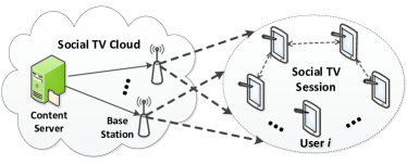
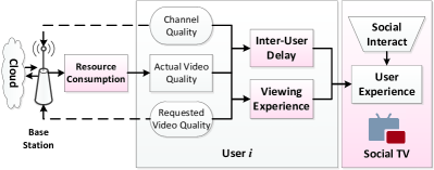
The elements of social TV user experience (i.e., video experience, inter-user delay and resource consumption) and their decisive factors (i.e., the actual and requested playback rate, and the channel dynamics) are plotted in Fig. 2. When deployed over wireless networks, a primary bottleneck is the uncertainty of wireless channel quality, which influences user experience in terms of both inter-user delay and video quality. Meanwhile, the requested video quality, together with the actually obtained video quality, determines the QoE of each user. Therefore, The social TV cloud should maximize the overall perceived video quality by optimally allocating resources to users according to their dynamic channel states and requested video quality.
The major symbols used in this paper are defined as follows:
-
•
- Average resource budget per user
-
•
- Maximum inter-user delay among users
-
•
- Playback duration of a video segment
-
•
- Available transmission rate of the th user
-
•
- Requested segment size of the th user
-
•
- Transmission delay of the th user
-
•
- Viewing experience of the th user
-
•
- Allocated segment size of the th user
II-B Resource Constraints
II-B1 Storage Model
Upon the establishment of each session, the Social TV cloud will allocate resource for each user. Specifically, the edge server will store the video segments for each user and the base station is responsible for the transmissions of those segments. Both tasks incur certain monetary cost [15]. For each resolution corresponding to the actual segment size of user , the storage cost is
where the storage cost is unit per bit.
II-B2 Wireless Communication Model
We consider a dynamic channel model in which the available data rate may change over time, depending on the channel quality. Under a general wireless channel , where is the power gain and is additive white Gaussian noise, the th user’s available transmission rate is given by
| (1) |
where is the fixed transmission power at the BS, is the channel bandwidth, and is the power spectral density of noise.
Since Social TV subscribers are mostly located in urban environment with access to 3/4G services or Wi-Fi, the power gain is assumed as a Rayleigh distributed random variable. Denote by the channel gain-to-noise ratio, the cost per Watt, the wireless communication cost per bit becomes
| (2) |
which is solely influenced by the dynamic channel gain .
Hence, the communication cost model is
Finally, consider an -user social TV session with total budget , the resource constraint reads as
| (3) |
II-C Inter-User Delay Model
In this section, we focus on the delay of each segment. For each segment, the transmission delay is mainly determined by two factors – the video quality of the segment, and the channel quality. For the th user, the former corresponds to the size of the transmitted segment , and the latter is measured by the available transmission rate . By plugging in (1), we obtain the segment transmission delay as
| (4) |
In practice, while the current video segment is being played, the next segment is being downloaded in the background at the same time. In such cases, the user will not notice any delay if the transmission delay is shorter than the segment play time . For this reason, we define a more meaningful “inter-user play delay” as follows
| (5) |
To ensure the virtual living-room experience, we introduce the following “inter-user delay constraint” to upper bound the maximal inter-user delay among all users
| (6) |
where is the maximum tolerable inter-user delay.
II-D Quality of Experience Model
The video viewing experience is a function of the requested and acquired video quality, measured by a metric called QoE. A logarithmic QoE function is initially proposed in [16] to fit the mean opinion score (MOS) from a large audience watching the same video. Due to its demonstrated accuracy especially in telecommunication services such as audio [17] and video streaming [10], we adopt this logarithmic model. A practical QoE model has the following form
| (7) |
where and are requested and allocated segment size, respectively, and , , and are parameters determined by the video content and other system features. They are obtained by fitting the logarithmic function to empirical data.
II-E Optimization Problem
The objective of social TV service is to maximize the overall QoE for each session, by optimally allocating playback rate to every participant. To achieve this target, we need to deal with two kinds of dynamics. On the one hand, the users may request for different qualities of the video according to various aspects, e.g., a tablet usually requires higher resolution than a smart phone. Likewise, an action movie may consume higher playback rate than a scenery video. On the other hand, the wireless channel states varies greatly depending on the user’s location and moving speed, affecting both the available transmission rate and the per bit cost. This in turn pose a limit on the actual playback rate provided to each user.
Mathematically, the stated problem converts to the following constrained optimization problem
| (8) |
where is the allocated segment size vector to be optimized, and and stand for the resource constraint and the inter-user delay constraint, respectively. We further assume that the allocated playback rate should not exceed the requested playback rate. Therefore, the optimization is formally given as
| (9) | ||||
| (10) | ||||
| (11) | ||||
| (12) |
III Optimal Playback Rate Allocation
III-A Derivation of Solution
Through examining the optimization problem and its constraints, we have the following observations. First, the objective function is convex because its Hessian matrix is positive definite. Second, both the resource constraints and are linear and convex sets. However, the inter-user delay constraint is complex and need further inspection.
Therefore, we adopt a divide-and-conquer strategy based on , which may be re-written as follows
It can be found that if , the nonlinear operator may be removed. Note that we assume to avoid trivial problem, i.e., all-zero play delay case. Thus, the original problem may be divided into two subcases, and .
III-A1 Moderate Delay Case
The former subcase corresponds to not-too-bad channel quality, and at least one user finishes transmission within . In such case, since by definition, can be replaced by a set of linear constraints as follows
| (13) |
Note that the above constraint is a linear and convex set, we use Lagrange multiplier method to solve the problem. After converting the maximization problem into the corresponding minimization problem and introducing a set of slack variables, the Lagrangian function under is given by
| (14) |
Using KKT conditions, we can find a global optimum by solving the following equations
| (15) | ||||
| (16) | ||||
| (17) | ||||
| (18) | ||||
| (19) | ||||
| (20) | ||||
| (21) |
Since the above system of equations are not only linear but also full rank, it can be easily solved. In this paper, we directly use the solver (fsolve) provided by Matlab.
III-A2 Severe Delay Case
When all users in a session suffer from deep channel fading, all transmission delays are larger than . Again, the nonlinear operator can be removed, and we have
| (22) |
Thus, may be replaced by a set of nonlinear constraints as
| (23) |
Note that compared with (13), is replaced by an unknown variable . Thus, we cannot directly apply the previous method. Instead, we resort to Lagrange dual method which iteratively converge to the optimum. In particular, we denote
| (24) |
Thus, the Lagrange function is
| (25) |
Take the derivative of , we have
The optimal playback rate has the following form
| (26) |
The Lagrange multipliers in (26) are obtained in an iterative fashion using the following equations
| (27) | ||||
| (28) | ||||
| (29) |
and most importantly, the iterative algorithm finds the minimal transmission delay, i.e., in each round and uses it to update the following coefficient
| (30) |
where is the step size used to control the convergence speed and accuracy.
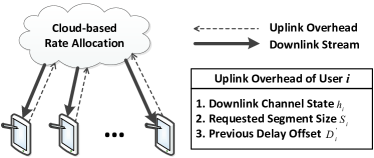
III-B Implementation of Optimal Solution
The playback rate allocation protocol is illustrated in Fig. 3. At the beginning of each segment cycle, each user reports to the cloud through the uplink overhead. The latter contains important local information such as downlink channel state , requested segment size and delay information of the previous segment . Note that the channel state can be easily obtained through downlink channel estimation. Altogether they serve as the inputs of the rate allocation algorithms implemented in the cloud, or more specifically, the edge server of the video source.
The social TV cloud will execute Algorithm 1 by default and switch to Algorithm 2 under severe delay. If history delay information is available, the server may assume that delay status remains the same and choose algorithm accordingly. Note that this is computation-efficient because the delay status, along with the channel status and user request, usually does not change very frequently. However, once a delay status change is detected, the server can freely switch between algorithms as described in the pseudo codes.
Note that although our algorithm is performed within one segment cycle, it can be easily modified to run over consecutive segments. Recall the inter-user delay constraint (6), we only need to modify this constraint by adding the delay offset of the previous segment into the current delay as follows
| (31) |
With the modified “accumulative delay constraint”, the residual delays of previous segments are passed on to the current segment, so that our proposed scheme can perform “adaptive rate allocation” over time. From the audiences’ perspective, the delay difference between any two users is constantly bounded, and the user experience is enhanced for the entire video.
IV Numerical Analysis and Results
IV-A QoE Dataset and Parameter Setting
Our QoE model in (7) is synthesized from viewing experience tests in which non-expert volunteers give scores (scaling from 1 to 5) based on their perceived video quality. We follow standardized procedures specified in the Adjectival Categorical Judgment Methods in [18] and the ITU recommendations [19]. The play time of each video is 10s, the same length as a video segment in our setting.
| Duck Video | Crew Video | Ice Video \bigstrut | |||
|---|---|---|---|---|---|
| Rate | MOS | Rate | MOS | Rate | MOS \bigstrut |
| 19484.0 | 5.0 | 6520.8 | 5.0 | 2302.6 | 5.0 \bigstrut[t] |
| 8108.5 | 5.0 | 2428.8 | 4.0 | 1133.3 | 5.0 |
| 2878.9 | 4.0 | 1275.0 | 3.5 | 573.0 | 4.0 |
| 1311.9 | 3.4 | 622.3 | 3.0 | 336.7 | 3.0 |
| 1177.3 | 3.0 | 466.6 | 3.0 | 270.8 | 3.0 |
| 621.5 | 3.0 | 394.1 | 2.0 | 208.9 | 2.5 |
| 142.2 | 2.0 | 104.5 | 1.4 | 61.4 | 2.0 |
| 117.0 | 2.0 | 72.2 | 1.4 | 42.9 | 2.0 |
| 76.8 | 2.0 | 48.2 | 1.0 | 28.7 | 2.0 \bigstrut[b] |
In our experiments, three different videos, i.e., duck, crew and ice, representing high, medium and low playback rate respectively are played in H.264/SVC format. Their mean opinion scores (MOS) are shown in Table I. The parameters in (7) are determined by minimizing the mean squared error (MSE) between the synthetic model and the real data. These parameters and their corresponding MSEs are given in Table II, where is set as one to avoid negative QoE. It can be seen that the logarithmic QoE function is quite accurate for all videos.
| Min Rate | Max Rate | MSE \bigstrut | |||
|---|---|---|---|---|---|
| Duck | 0.634 | 1554.8 | 76.8 | 8108.5 | 0.0514 \bigstrut[t] |
| Crew | 0.802 | 419.6 | 48.2 | 2428.8 | 0.057 |
| Ice | 0.765 | 297.3 | 28.7 | 1133.3 | 0.161 \bigstrut[b] |
Our wireless model follows (1) and we generate independent and identically distributed (i.i.d.) Rayleigh fading channel with normalized average channel gain for each user. Without loss of generality, the channel bandwidth is set as MHz and unit per bit cost is assumed for both the storage and communication. The playback duration of each segment is 10s. To guarantee social experience during watching, the maximum allowed play delay gap between users is three seconds.
We first briefly describe two extreme rate allocation schemes as performance benchmarks:
-
•
Maximal QoE Scheme: the Social TV cloud allocates as much available resource as possible to satisfy each user’s QoE demand, while completely ignoring the delay constraint.
-
•
Minimal Delay Scheme: the Social TV cloud allocates resource proportional to their available transmission rate . In this case, each user has the same delay, thus the delay gap is minimized to zero.
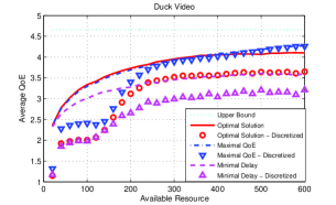
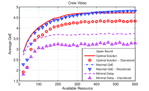
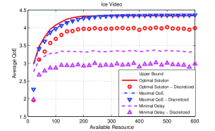
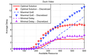
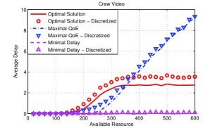
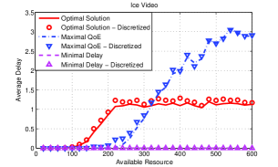
We first examine the QoE and delay performance versus available resource. Specifically, the available resource is roughly proportional to the maximal playback rate that can be allocated to users. As seen in Fig. 4, all resource-QoE curves (solid line, dashed line and dash-dot line) are also roughly governed by the logarithmic rate-QoE function. The maximal QoE scheme and our optimal solution generate the highest QoEs, and the minimal delay scheme has the worst QoE. Fig. 5 shows the resource-delay curves, in which the minimal delay scheme has zero inter-user delay and the maximal QoE scheme has unbounded inter-user delay. The inter-user delay of our scheme increase with the available resource but is ultimately upper bounded within tolerable value.
Combining Fig. 4 and Fig. 5, it can be seen that the minimal delay scheme forces low inter-user delay at the cost of poor QoE, while the maximal QoE scheme suffers from unbounded delay. For all three video types, our proposed optimal solution achieves near-maximal QoE, while their inter-user delays are strictly controlled within the allowed range, i.e., less than three seconds. Thus, our solution achieves near-optimal tradeoff between higher QoE and lower inter-user delay.
As far as the video type is concerned, the obtained QoE grows faster for videos with lower rate (e.g., the crew and ice videos) and slower for videos with higher rate (e.g., the duck video), and they finally achieve the theoretical upper bound granted sufficient resource. This is intuitive because higher rate videos usually require more resource. Moreover, the QoE gain over the minimal delay scheme is more significant for videos with lower rate, because they have more free resource for optimal rate allocation.
IV-B Adaptive Rate Allocation
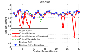
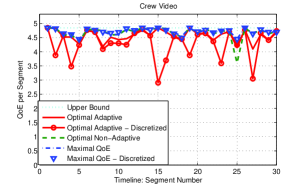
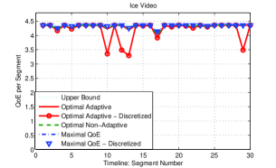
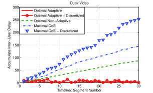
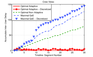
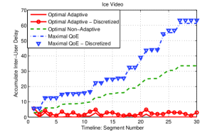
We implement an adaptive rate allocation scheme described at the end of Section III-B, by applying the “accumulative delay constraint” in (III-B). The essence of the adaptive scheme is that the accumulative inter-user delay, instead of the only the current segment’s delay, is taken into account, so that the user experience does not deteriorate over time. The realtime QoE and accumulative inter-user delay are shown in Fig. 6 and Fig. 7. We generate i.i.d Rayleigh fading for each segment to emulate very fast changing channels. As seen, the adaptive version occasionally incurs additional performance loss from its non-adaptive counterpart, but the overall good performance is preserved. Additionally, the inter-user delay is bounded throughout the video, so that the virtual living room experience is also guaranteed.
IV-C Discrete Video Resolution
Till now, we assume continuous segment size for both requested and allocated video, so that the potential benefit of the proposed rate allocation scheme may be fully demonstrated. However, our current Social TV framework only support up to five resolutions. Hence, we further simulate the case that the segment size can only take five values. Note that we ensure that the resource constraint is still satisfied when approximating the continuous value to the nearest discrete value. The discretized version of all curve are shown by markers from Fig. 4 to Fig. 7. As seen, discretization incurs performance loss in terms of both the QoE, especially for higher rate video. Nevertheless, the good performance is largely preserved, and the discrete scheme is still effective.
V Conclusions
In this paper, we introduce the user experience of social TV, and provide an optimal playback rate allocation scheme. Specifically, our scheme can dynamically allocate resource in response to the rapidly changing channel quality and user request. The proposed scheme maximizes the overall QoE while upper bounding inter-user delays among all users, thus ensuring both the perceived video quality and the virtual living room experience. We also provide implementation details, and show through experiment that our algorithm achieves near-optimal tradeoff between video quality and inter-user delay, and performances well even under fast channel fading.
References
- [1] Y. Wen, X. Zhu, J. Rodrigues, and C. Chen, “Cloud mobile media: Reflections and outlook (invited paper),” IEEE Transactions on Multimedia, To Appear, 2014, to appear.
- [2] M.-J. Montpetit and M. Médard, “Social television: Enabling technologies and architectures,” Proceedings of the IEEE, vol. 100, no. Special Centennial Issue, pp. 1395–1399, 2012.
- [3] Z. Yu, X. Zhou, L. Zhou, and K. Du, “A hybrid similarity measure of contents for TV personalization,” Multimedia systems, vol. 16, no. 4-5, pp. 231–241, 2010.
- [4] P. Cesar, D. C. Bulterman, and A. Jansen, “Usages of the secondary screen in an interactive television environment: Control, enrich, share, and transfer television content,” in Changing television environments. Springer, 2008, pp. 168–177.
- [5] Y. Jin, T. Xie, Y. Wen, and H. Xie, “Multi-screen cloud social TV: transforming TV experience into 21st century,” in ACM International Conference on Multimedia, 2013, pp. 435–436.
- [6] X. Li, T. Xie, Y. Wen, and H. Xie, “Multi-screen social TV over cloud-centric media platform: Video presentation,” in International Conference on Mobile Systems, Applications and Services, 2013.
- [7] R. Rejaie, M. Handley, and D. Estrin, “Quality adaptation for congestion controlled video playback over the internet,” SIGCOMM Computer Communication Review, vol. 29, no. 4, pp. 189–200, Aug. 1999.
- [8] Z. Li, A. C. Begen, J. Gahm, Y. Shan, B. Osler, and D. Oran, “Streaming video over HTTP with consistent quality,” preprint arXiv:1401.5174, 2014.
- [9] S.-H. Shen and A. Akella, “An information-aware QoE-centric mobile video cache,” in ACM International Conference on Mobile computing & networking, 2013, pp. 401–412.
- [10] W. Zhang, Y. Wen, Z. Chen, and A. Khisti, “QoE-driven cache management for HTTP adaptive bit rate streaming over wireless networks,” IEEE Transactions on Multimedia, vol. 15, no. 6, pp. 1431–1445, Oct 2013.
- [11] V. Joseph and G. de Veciana, “NOVA: QoE-driven optimization of dash-based video delivery in networks,” preprint arXiv:1307.7210, 2013.
- [12] J. Llorca, K. Guan, G. Atkinson, and D. C. Kilper, “Energy efficient delivery of immersive video centric services,” in IEEE INFOCOM, 2012, pp. 1656–1664.
- [13] Y. Jin, Y. Wen, K. Guan, D. Kilper, and H. Xie, “Toward monetary cost effective content placement in cloud centric media network,” in IEEE International Conference on Multimedia and Expo, 2013, pp. 1–6.
- [14] Y. Jin, Y. Wen, G. Shi, G. Wang, and A. Vasilakos, “Codaas: An experimental cloud-centric content delivery platform for user-generated contents,” in IEEE International Conference on Computing, Networking and Communications, 2012, pp. 934–938.
- [15] Y. Jin, Y. Wen, and H. Hu, “Minimizing monetary cost via cloud clone migration in multi-screen cloud social TV systems,” in IEEE Global Communications Conference, 2013, pp. 1–6.
- [16] P. Reichl, S. Egger, R. Schatz, and A. D’Alconzo, “The logarithmic nature of QoE and the role of the Weber-Fechner law in QoE assessment,” in IEEE International Conference on Communications, 2010, pp. 1–5.
- [17] P. Reichl, B. Tuffin, and R. Schatz, “Logarithmic laws in service quality perception: where microeconomics meets psychophysics and quality of experience,” Telecommunication Systems, vol. 52, no. 2, pp. 587–600, 2013.
- [18] I. Recommendation, “500-11, methodology for the subjective assessment of the quality of television pictures,” International Telecommunication Union, 2002.
- [19] I.-T. Recommentation, “Subjective video quality assessment methods for multimedia applications,” 1999.