Application of Ontologies in Identifying Requirements Patterns in Use Cases††thanks: This is partly funded by project LATiCES (ref. NORTE-07-0124-FEDER-000062), co-financed by the North Portugal Regional Operational Programme (ON.2 - O Novo Norte), under the National Strategic Reference Framework (NSRF), through the European Regional Development Fund (ERDF), and by national funds, through the Portuguese foundation for science and technology (FCT).
Abstract
Use case specifications have successfully been used for requirements description. They allow joining, in the same modeling space, the expectations of the stakeholders as well as the needs of the software engineer and analyst involved in the process. While use cases are not meant to describe a system’s implementation, by formalizing their description we are able to extract implementation relevant information from them. More specifically, we are interested in identifying requirements patterns (common requirements with typical implementation solutions) in support for a requirements based software development approach. In the paper we propose the transformation of Use Case descriptions expressed in a Controlled Natural Language into an ontology expressed in the Web Ontology Language (OWL). OWL’s query engines can then be used to identify requirements patterns expressed as queries over the ontology. We describe a tool that we have developed to support the approach and provide an example of usage.
1 Introduction
Developing software systems according to the stakeholders’ expectations is a well known problem in the software engineering area. One of software engineering’s major goals is to reflect the stakeholders concerns in the final solution, in order to provide useful software systems. With traditional approaches [20], requirements are specified at the beginning of the development process, and those specifications are used as guides for development. However, there is a gap between user requirements and the software development process, which might result in the misunderstanding of the stakeholders’ concerns.
Use cases are a popular method for requirements specification which contributes to solve this problem. They were proposed by Jacobson [13] and later adopted by the Object Management Group (OMG). A use case model is composed of two parts: a graphical representation that summarizes the user interactions with the software system being described; and the specifications of each individual use case.
Use cases mainly represent user functionalities and, as such, provide knowledge to derive high level information about the software systems they describe. We aim to extract such information from the use cases, by means of an automated process. Hence, we present an approach to both formalize the use case specifications, and extract requirements patterns (which represent common concerns among several stakeholders) from them. To enable this, use cases must be specified in a Domain Specific Language (DSL), which takes the form of a Controlled Natural Language (CNL). In order to gain the reasoning leverage needed for identifying the patterns, we propose to use the inference capabilities of an ontology (in this case the Web Ontology Language (OWL)). To achieve this, we developed a transformation from use cases expressed in the adopted DSL into an OWL ontology.
Our approach aims at several benefits on requirements based software development. First, by providing a DSL, it aims at allowing stakeholders to take part in the specification process. The DSL is at the same time formal and computable, yet, it is adequate for users to specify statements with due to being close to natural language. Second, we aim also at improving the process of going from the requirements’ specification to the final system. The use of a formal DSL will allow us to predict errors and misunderstandings in requirements earlier in the software development process. The assembling of architectural patterns [5], inferred from the requirements patterns, will support rapid prototyping of the system. At this stage, we have implemented a tool for requirements specification in order to explore these possibilities. The tool supports the specification of user requirements in a textual format, using the defined DSL. It then transforms the requirements into an OWL ontology, in which we are able to perform queries, and extract requirement patterns.
In order to illustrate our approach, we present an example of an online Content Management System (CMS) for software models. We intent to equip it with functionalities requested by the stakeholders as use case descriptions. We will consider, for instance, the possibility to upload a model.
The remaining of this work is organized as follows. Section 2 introduces related work. In Section 3 we present the proposed approach with an example. We present our tool in Section 4, again using the example. In Section 5 we discuss the results achieved to date, and leave suggestions for future work.
2 Related work
2.1 Languages for expressing use cases
Although there is no standard way to specify individual use cases, they are typically described in relatively free form textual formats (see, for example, Fowler [9] or Cockburn [6]). One of the advantages of these textual descriptions of the scenarios composing a use case is that they allow for flexibility in the specifications. Unfortunately, they make it more difficult to formalize and operationalize the information in the scenarios. Furthermore, when stakeholders take part in use case specification, they typically use natural language to describe the scenarios. Such specifications can be ambiguous and lead the development team in error.
Hence, approaches that propose analyzing use cases to extract implementation relevant information (e.g. architectural information) need to formalize languages in which use cases must be specified. Somé [22] presents an approach for software reengineering in which use cases play a central role as primary input, using a restricted form of natural language for use cases description. Similarly, Biddle et al.describe Essential Use Cases (EUC) [4] as an approach to operationalize use case descriptions. By reducing and restricting the language used in the use case descriptions, the authors were able to perform object oriented software development without intermediary transformations. The work by Biddle et al.is further supported with design patterns and composition techniques for EUC [3]. They present the specification for describing patterns for EUC, as well as a pattern catalog. Executable use cases [14] are another kind of restricted use cases, with computable capabilities, and with a defined mapping to Coloured Petri Net (CPN).
Our work takes from the above approaches the need to formally define a language for expressing use cases. We propose an approach to specify the stakeholders’ requirements in a CNL [21]. The objective of using a CNL is twofold. First, we want to allow stakeholders to take part in the requirements specification, providing a language understood by both stakeholders and developers. Second, we want to be able to transform use case specifications into other languages supporting the patterns identification mechanisms we want to achieve. We consider CNL to provide a good compromise between formalism and computability.
2.2 Web Ontology Language (OWL)
In order to reason about the information present in the use case descriptions, we need some form of knowledge representation and inference mechanism. Ontologies are a possibility to achieve this. They provide the means to formally represent knowledge as a set of concepts, in a specific context. We are particularly interested in OWL [19].
OWL allows us to create domains for information specification, and provides tools to reason about their knowledge. The World Wide Web Consortium (W3C) specified three levels of formalism for the OWL language. The first level, OWL Lite, is intended to simplify the specification of OWL ontologies. The second level, OWL DL, is intended to provide maximum expressiveness, while retaining the inference capabilities. Finally, the third level, OWL Full, is a more complete language which preservers compatibility with Resource Description Framework (RDF), but has no reasoner available. Several syntaxes are available to write OWL ontologies, as is the case of Manchester111Specification available at http://www.w3.org/2007/OWL/wiki/ManchesterSyntax, last accessed in 2013-12-11 and Sydney [11].
All OWL ontology elements, and the ontology itself, contain an Uniform Resource Identifier (URI) which specifies the resource’s location. Such web capability allows us to use and share domain concepts, among several locations. This not only promotes sharing and reuse of acquired knowledge among several projects, but also supports modelling web environments by providing all elements with a specific location.
The expressiveness of OWL allow us to define requirements ontologies as well as their instances, and to perform queries over such knowledge. While an ontology corresponds to a set of concepts for a specific domain, its instance is a set of concrete values, for those concepts. In OWL those concepts are the classes (which are related between them), such as an Actor. The concrete values for those classes are the individuals (c.f. instances of the classes), as for instance a user, which might be an instance of Actor. For OWL, the W3C specifies a set of components222Full list of allowed elements in http://www.w3.org/TR/owl2-manchester-syntax/, last accessed in 2013-12-11, from which we highlight the following ones, due to their relevance for our purposes:
-
•
Class - A type (Class) of elements.
-
•
Individual - A class instance.
-
•
ObjectProperty - A relationship between two elements (for instance between two Individual).
-
•
DataProperty - Data associated with an Individual.
-
•
AnnotationProperty - An annotation associated with an element.
-
•
DataType - A specific kind of data (for instance xsd:string).
Several authors have proposed the use of OWL in support for software engineering. Dietrich and Elgar present an approach to formally describe design patterns in OWL [8]. They perform a mapping between design patterns and OWL to enable design patterns’ inference. The Semantic Web Rule Language (SWRL) rules provide the pattern inference capabilities. The work reported by Kirasić and Basch is another example of pattern inference on OWL, resorting to SWRL rules [16]. OWL was also successfully used to extract other kind of knowledge, such as rationale informations from textual documents, as presented by López et al.[18]. Following these works, we intent to use OWL to represent the knowledge present in use case descriptions, and then use its inference capabilities to identify patterns in their knowledge.
2.3 From CNL to OWL
A number of approaches that map Controlled Natural Languages (CNLs) onto ontologies, and onto OWL in particular, can be found in the literature. One example is the Rabbit language [12], defined to enhance communication between domain experts and ontology engineers, and the general purpose Sydney OWL syntax [11]. Other examples, are the Lite Natural Language, which is tailored for formal mapping and optimized for computational tasks [2], and Attempto Controller English (ACE), a more expressive language than OWL into which a mapping for a subset of OWL has been defined [15].
The work reported by Kuhn shows how controlled natural languages are easier to understand than the OWL standard notations [17]. His work is of special interest, since the author was able to successfully map an CNL to OWL, in order to improve OWL’s readability [17]. A list of CNL statements is presented in ACE. Such statements have a respective OWL mapping, which allows mapping controlled english into declarative OWL statements. This results in statements which need less learning time and are more accepted by the users.
3 The proposed approach
We propose a framework to extract common requirements’ specifications from use case descriptions, as depicted in Figure 1. In the figure, the full arrows represent the process flow, while the dashed arrow represents information flow. The use case allows the use of a restricted natural language, specifically, we propose the use of a CNL. Without reducing flexibility, the CNL improves the data extraction possibilities.
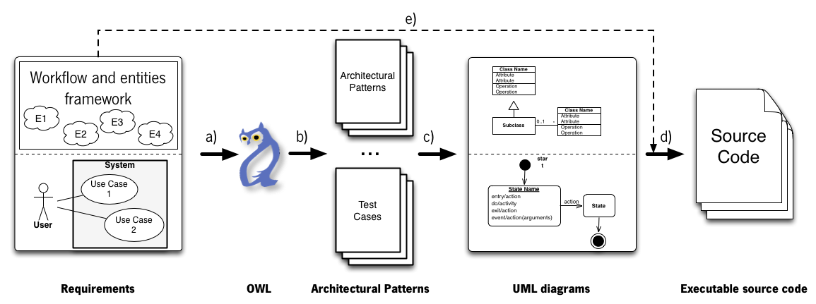
Our process starts with the input of the use case descriptions (see Figure 1, Requirements). In order to specify the use cases in a more controlled context, we introduce the Workflow and Entities framework. Such framework indexes our tool to a specific domain. When specifying the use cases, the authors resort to the entities in the domain, whose meaning is the same across all of the process. We consider OWL to be adequate for our purposes for its declarative specifications and reasoning capabilities, compatible with our DSL and our objectives. From the three OWL’s levels of formalism, we are interested in the Web Ontology Language description logic subset (OWL-DL), which has powerful inference capabilities and is supported by several reasoners. Figure 1 (phase OWL) illustrates that we transform the use case specifications into OWL.
The expressiveness of OWL allow us to define requirements ontologies and to perform queries over such knowledge. Resorting to the reasoners, we are able to query them, and extract patterns from them. We propose to extract requirement patterns from the use case specifications, after mapped onto OWL. The transition b) and phase Architectural Patterns (Figure 1) represent how we expect to extract the requirements patterns and integrate architectural patterns in the process. We have developed a tool (described in Section 4) which supports the ontology creation from use case descriptions, in order to validate our approach.
The two last steps of the proposed approach, the UML Diagrams and the Executable source code steps, are future work. They represent the Unified Modeling Language (UML) diagrams (both structural and behavioral) to extract from the requirements patterns that, when assembled, will lead us to the source code. The dashed arrow e) represents how the entities and workflow framework provide the additional informations to achieve executable prototypes (as they contain the platform specific details). We detail these phases in Section 5.
3.1 The use case description
Typical use case descriptions are known to contain platform details, reflect user interface elements and, possibly, be ambiguous [4]. In Figure 2 we have an example of a use case specification (which should be provided by the stakeholders). This is a traditional use case, where the actor inputs and the system responses to such actions are specified. Figure 2 exemplifies how a user adds a new model to a web CMS. We will refer to Figure 2 during the remaining of this paper in order to present our approach.
| User (Actor) input | System (Actor) response |
|---|---|
| Clicks in the New Model link | |
| Presents form with name, description, scope, language, file and image | |
| Provides the requested fields | |
| Clicks the save button | |
| Validates the name, description, scope, language, file and image | |
| Creates a new model | |
| Lists all the models |
3.1.1 Possible approaches
The verbosity of traditional use cases makes them hard to use in computational tasks. Due to the natural language complexity, it is possible to find all kind of details in the use cases, such as platform specific elements or elaborated text, which make the sentences harder to analyze. It is also possible to express the same thing in several distinct ways, and that makes it even harder to process the use case textual descriptions. The use case descriptions tend to provide other details than the required ones, which are unnecessary informations for our purposes. An alternative to traditional textual use case specifications are EUC [7]. They are simplified versions which aim to create more abstract and concise specifications. In our approach, and as we are interested in creating computable representations, we aim to generate use case specifications similar to EUC. A way to achieve those specifications, is by guiding the user to create simple and objective statements in the use case description, mainly composed by the specific scenario elements.
To specify our simplified use cases descriptions, first we need a definition of a language. An interesting language (ACE) is presented by Fuchs and Schwitter [10]. As discussed in Section 2, Kuhn [17] presents a study where the author describes how the ACE language can be translated into OWL, and more interestingly, how ACE improves the readability and understandability of the statements. The ACE language targets at improving the specification of OWL statements and knowledge scenarios description, and not at use case definition. For that, we consider it unsuitable for our purposes, as we need a flexible language for use case descriptions. Inspired by ACE, we have defined a DSL specification, which we have called the Restricted Use-Case Statements (RUS) language. A RUS file contains the valid statements for the use case description specifications. It defines both the allowed input format, and the corresponding transformation of that specification to an ontology language.
We consider that in our approach, the RUS inherits from ACE its two major strengths. First it supports the writing of more natural and easier to understand statements. Second it can be translated into OWL statements.
The ACE language defines three kinds of tags. Individuals (the <I> tag – cf. OWL entities), types (the <T> tag – cf. OWL classes) and relationships (the <R> tag – cf. object properties). We added the <D> tag for data properties, a type of element not covered in ACE.
In Kuhns’ work, a set of translations from ACE directly into “Manchester-Like Language” (MLL) is specified [17]. While the Manchester syntax is a compact syntax to specify OWL ontologies, the MLL is a (non standard) restriction of that language. Based in those specifications, we specified the Manchester language equivalent to Kuhn’s MLL. Since Kuhn has defined a transformation from ACE, it is then possible to have transformations from ACE to OWL (Manchester language). RUS entries are descriptions of transformation rules from ACE to Manchester language. Table 1 presents in the first column the ACE format, in the second column the Manchester-Like Language representation and in the third column we defined the original Manchester Language statement.
| ACE | MLL | OWL Manchester |
|---|---|---|
<I1> <R> <I2> |
<I1> <R> <I2> |
Individual: <I1> Facts: <R> <I2>
|
<I1> does not <R> <I2> |
<I1> not <R> <I1> |
Individual: <I1> Facts: not <R> <I2>
|
<I> is a <T> |
<I> hasType <T> |
Individual: <I> Types: <T>
|
3.1.2 The RUS language
The RUS is a flexible template language, which allows developers to specify formats for use case descriptions. Each RUS is composed by two parts, the input format and the target format.
The first part (input format) has two components: the placeholders and the keywords. The placeholders are words (between “” and “”) which mark the locations where the user will input text. That text will result in data for the ontology. If we want a placeholder to accept multiple values, it should have the sign on front of it. The keywords are free text words which help to improve the statements readability. This input format can have two or three placeholders depending on the users’ needs, and as many keywords as required. This first part defines the format in which the user must write the statements.
The second part (the target format) is a set of four comma separated components (4-tuple), corresponding to the final format of the user’s input. The first component is the ontology entity which the use case will affect. The second component is the placeholder corresponding to to the actual entity (from the first part of the RUS statement). The third component is the property that will be attributed to the second component, and the fourth component is its value.
Briefly, the first component identifies how the user should write the requirements in CNL. It enables the validation of the use case description input, and at the same time the generation of parsing rules. The second component allows the specification of how the extracted informations (specified according to the first component) should be mapped into the final ontology.
Listing 1 presents an example of a RUS file that allows the specification of the model upload use case. From the RUS file, we are able to extract two kinds of information. First, it is possible to extract a grammar, which produces a parser able to extract individuals, relationships, types and properties from the user specifications. Second, we are able to extract a set of regular expressions, which allow the runtime validation of the user requirements’ statements.
3.1.3 RUS example
Consider the entries in Listing 1. The elements between “” and “” are the placeholders (where the user should input text). Words proceeded by an underscore (for instance _has in line 3) are mandatory keywords. The arrow (->) separates the two components.
Regarding the entry in line 1, the first component states that an individual (<I>) is related (<R>) to another individual (second <I>). The second component, which specifies the target format, is specified with a 4-tuple of elements, separated by commas: Target_Entity_Description, Target_Entity, Entity_Property and Property_Value. In this 4-tuple, the element Target_Entity_Description specifies which OWL element is this information related to (in the example, an Individual).
The Target_Entity element is the instance element, of the type Target_Entity_Description. The element must be a placeholder (<I>, <R>, <D> or <T>, from the first component of the RUS instruction). In this example, it is an instance of an OWL individual (<I>).
The Entity_Property element corresponds to a property of the Target_Entity. For an Individual, it is possible to have properties such as Types and Facts. In the example a Fact is being described. It specifies where the Property_Value element should be added at the target element.
The last element, is the Property_Value, which is an Entity_property value. It should contain the placeholders, and may also contain other OWL allowed keywords (for instance not and or).
The presented entry allows us to declare statements identifying that an individual performs an action on another individual. For example: user clicks newModel. According to the rule, this entry is translated into: Individual:,user,Facts:,clicks newModel.
This example states that an user (first individual) clicks (relationship) the newModel (second individual). As specified by the entry, this statement is translated into the following Manchester OWL statement:
It is also possible to specify Restricted Use Case (RUS) statements with a variable number of entries by appending ’+’ to the statement, as illustrated in the second line of Listing 1. An example of a (simplified) statement which relates an Individual (<I>) with a set of Individuals (<I>+) is illustrated by:
This input states that the user (<I>) provides (<R>) the name and the description (<I>+). This input is divided into several equivalent statements, as presented next.
These statements can now be easily mapped into OWL as presented in Listing 2 (see Section 3.4), as they can be translated to the 4-tuple format (with the entry on the first line, in Listing 1).
| User input | System response |
|---|---|
| user clicks newModel | |
| system requests : name, description, scope, language, file, image | |
| user inserts : name, description, scope, language, file, image | |
| user clicks save | |
| system validates : name, description, scope, language, file, image | |
| system creates model | |
| system list models |
3.2 Extraction of entities
Given a use case as the one in Figure 3, in the first steps of our approach we are interested in extracting the entities and 4-tuples from the use case description. There are two distinct inputs in this step. The first one, is the specification of the allowed language, the RUS. The second one is the use case itself. The RUS allow us to create the grammar, which will extract informations from the use case. From the grammar file, a set of parsers able to extract the entities and 4-tuples from the requirements are achieved. Currently, it is possible to create two kinds of parsers. The first one allows the extraction of the list of entities, relationships, individuals and data properties, contained in the requirements specification. The second one, allows the extraction of the set of 4-tuple statements.
With the RUS in Listing 1, we were able to extract from the use case in Figure 2, the set of entities presented in Listing 3, where r represents relationships (Object Properties) and i stands for Individuals.
We were also able to extract the 4-tuples presented below:
With this information, it is now possible to create an OWL ontology with the previously presented methodology. However, in order to create a complete instance, some more informations are required, related with the entities’ types.
3.3 Individuals and classes
Unless explicitly specified in the user requirements, both the classes and the individuals’ type information are missing. The individual to class association is crucial to create an ontology instance. In order to create it, the user must then specify all the relevant classes, and associate them with the individuals.
In our example, we propose a set of classes derived from the problem domain, as presented next.
The rationale for defining theses classes becomes clear when we specify the individuals to classes associations, as presented in Listing 4. With these informations, it is now possible to create an ontology and an instance.
3.4 Ontology and instance
In order to create the ontology, we have created a module which resorts to the Apache Jena framework333Available at http://jena.apache.org/, last accessed in 2013-12-04. This framework allows us to take the previously extracted information, map it into an OWL metamodel and create the source code.
Usually, the first element of an OWL ontology is a set of prefixes, which represent additional resources to enhance the ontology. Example of prefixes are the XML Schema Definition (XSD), OWL, Extensible Markup Language (XML), RDF, Dublin Core (DC) and RDF Schema (RDFS). For our purposes, some of these prefixes, such as OWL are mandatory, since we are defining OWL ontologies. Also, we need the RDF prefix, which is used as a flexible data representation for domain resources. Finally, after the prefixes, we can specify the ontology components.
With these informations, we were able to implement the tool which allows the creation of the ontology and respective instance (phase OWL in Figure 1). Resorting to the OWL standards, we are able to create ontologies which can be integrated and processed in other tools, such as the Protégé 444http://protege.stanford.edu, last accessed in 2013-12-09 ontology editor.
In order to exemplify our approach, we will resort to the first line of the use case description in Figure 3:
The described entry matches the rule in line 2 in the RUS file presented in Listing 1. From this rule it is possible to know which elements we should extract, namely individuals (user and newModel) and relationships (clicks). Next, the user should provide the types for the individuals. In this case, we have two individuals, the user and the newModel. Their types are Actor and Link, respectively (see Listing 4). With that information, it is finally possible to extract the following 4-tuple, which can be directly mapped into OWL.
The two first elements of the 4-tuple (Individual:,user), inform that we have an individual, named user. This information is reflected in the following OWL code.
The three last elements in the 4-tuple (user,Facts:,clicks newModel) state that the user, on the property Facts, will have the pair value ’clicks newModel’.
Finally, we have stated before that the user has the type Actor, hence we are able to reflect such information in OWL as follows.
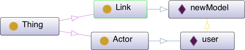
In Figure 4 we have an extract of the resulting ontology. The circles represent the classes, the diamonds individuals. The arrows between two classes are the SubClass (inheritance) relationship and the arrows between classes and individuals are the OWL class association (for instance, an user has type Actor). The dashed arrow between the individuals represents the clicks relationships.
3.5 Pattern inference
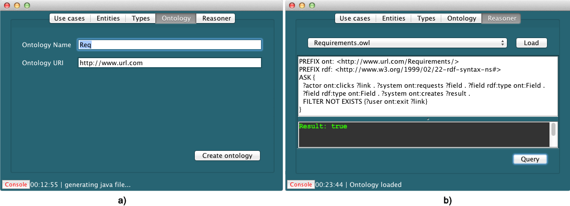
OWL provides several query languages, such as the SWRL and the SPARQL Protocol and RDF Query Language (SPARQL). In our approach we use SPARQL to query the use case specification data, mapped onto OWL. In order to infer the patterns, we describe the requirements patterns as SPARQL queries. Then, we apply those queries in the use case descriptions.
We present in Listing 5 a query which identifies the requirement to have a model upload functionality. The SPARQL language allow us to perform two kind of queries. On the one hand, the Select query, allow us to ask questions about an ontology and get results. On the other hand, there is the Ask query, which verifies if a statement is valid for a given ontology.
We query the knowledge base with the Ask statement, in order to identify if there is a user (?actor) which clicks in a link (?link) at a given web application (line 4), and that process results in a new model (?result, on line 5). The ?user will identify which Individual clicks on a given link. The ?system will relate the system’s requested data with the Field type. Also, the ?system will create the ?result, which should be a new model. This pattern requests also that the user does not exit the current page (i.e., perform the exit action), represented with the FILTER NOT EXISTS statement (on line 6).
The requirements pattern described in Listing 5, applied to the use case in Figure 3, returns the true value. The true value means that the rule is satisfied in the given ontology, therefore we have the model upload pattern in the user requirements.
The requirements patterns themselves provide informations about the user required functionalities. Such functionalities provide hints about implementation details. With more elaborated patterns and specifications, we expect to be able to associate architectural patterns with those requirements patterns. We are still exploring the OWL inference capabilities in order to mature our approach and to identify other data extraction possibilities.
4 The Use Case Analysis Tool
As already stated, the proposed framework is supported by a tool which guides the users when using our approach. We resort to the use case specified in Figure 3 in order to demonstrate our tool. We use the RUS in Listing 1 to specify the input language.
4.1 Use case specification
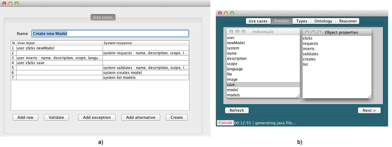
The tool supports the input of use case descriptions, in the textual format defined by the RUS in use. In Figure 5 a), we present the tool’s interface to specify the use case description. The user interface provides means to specify the user input and the system response. It is possible to see the model upload example (from Figure 3) in our tool. In the left column, we specify the user input, and on the right, the system response. The user might select the validate button, in order to check the input against the RUS. When the generate button is pressed, the tool generates ANTLR (ANother Tool for Language Recognition) parsers, and extracts the Individuals, Data properties and Object properties from the requirements input. It then proceeds to the next stage in the process (and the next screen: Entities).
4.2 Entities preview
Once extracted, the inferred entities are shown to the user, in the interface which our tool provides to query them. In Figure 5 b), it is possible to see the extracted Object properties (relations) and the Individuals. Among others elements, we have the entities user and newModel, and the clicks relation, which were used to illustrate our approach. When the user finishes the tasks in this screen, it may select the Types tab or click the Next button, in order to proceed to the next screen.
4.3 Individuals’ types
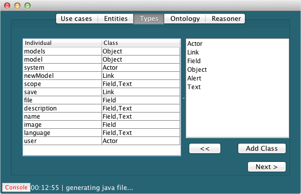
The individuals’ types information should be specified by the user, since we are not able to infer such information. Resorting to the interface depicted in Figure 6, the user should create the types (with the add button), and then assign one (or more) types to each individual. We have input a set of classes (Actor, Link, Field, Object and Alert), and associated them with the corresponding individuals. In this interface, we stated (for instance) that an user is an Actor. The classes are listed and created in the right side, and associated with the individuals listed on the left side. It is possible to associate several classes to the same individual, as is the case of the name, which is both an Object and a Field.
4.4 Ontology generator and Reasoner
The last step performed in our tool, is to provide the missing informations to generate the ontology. The user must specify a valid url (in our case, http://www.url.com), and select the Create Ontology option. Such action generates the corresponding OWL file, as presented in Figure 7 a). The file is a valid OWL ontology, described in OWL Manchester Syntax. We provide also a simple way to preview the generated file in its textual format. That functionality is also available to preview the RUS file.
Furthermore, it is possible to query the generated ontology from within our tool. Figure 7 b) depicts the interface which allows to write and execute SPARQL queries.
5 Conclusions and Future Work
In this paper we have presented an approach to formalize use cases in OWL, in order to support the identification of requirements patterns in the use case descriptions. Our approach started with the definition of a restricted natural language for requirements specification. Such format, the RUS, enables us to specify how user input should be expressed and how the resulting use cases can be transformed into an OWL ontology. The transformation rules provide us with most of the required information to create the ontology. However, the process is not fully automated, as information such the types of specific individuals cannot typically be inferred. We have implemented a prototype tool, which assists the user in inputing that missing information, at the same time as it shows the inferred knowledge. Our tool is then able to create the OWL ontology, with an associated instance. Resorting to OWLs’ query engines, we are able to perform queries over the ontology to identify requirements patterns in the use cases. Our approach was illustrated with an example use case for uploading a model to a CMS. Resorting to this example we present the implemented tool, which supports our framework. We also illustrated how requirements patterns could be identified in the example.
In order to further validate our approach we are interested in evaluating the expressiveness of the RUS. To do such, we will use the full requirements specification of existing software systems, and map them into our specification format. This, besides enabling to assess the expressiveness of the language, will enables us to further develop the requirements patterns and their identification. Indeed, our goal is to create a requirements patterns catalog by analyzing the requirements specifications of different software systems.
The proposed approach is part of a wider project which aims to create software prototypes, starting from use case specifications. To help in this process, we propose to focus on a specific domain, resorting to the entities and workflow framework. This feature is depicted in Figure 1, in the arrows e) and d). By associating requirements patterns with architectural patterns, as presented in our framework in Figure 1 - transition c), we propose to obtain hints about the final system implementation directly from the use cases. The case studies above can also be of use in this. By inferring architectural patterns presents in the use case specifications, we will be able to compare the actual implementations against the inferred patterns.
Finally, while at the moment we are mainly interested in extracting the entities and their relationships from the use case specifications, it is also possible to extract other kinds of information from the use cases, specifically behavioral aspects. We propose to analyze the possibility of extracting behavioral information from the use cases, for instance as CPN, activity or state machine diagrams. These models will allow us, not only to formally verify the use cases from a behavioral perspective, but also to simulate the use cases’ flow, via animated diagrams. This will help us to validate the use case specifications.
References
- [1]
- [2] Raffaella Bernardi, Diego Calvanese & Camilo Thorne (2007): Lite Natural Language. In: Proceedings of the 7th International Workshop on Computational Semantics, ISWC’07, Tilburg University.
- [3] Robert Biddle, James Noble & Ewan Tempero (2001): Patterns for essential use cases. In: Proceedings of KoalaPLoP 2001, KoalaPLoP ’01, Darlinghurst, Australia.
- [4] Robert Biddle, James Noble & Ewan Tempero (2002): Essential use cases and responsibility in object-oriented development. In: Proceedings of the twenty-fifth Australasian conference on Computer science, ACSC ’02, Darlinghurst, Australia, pp. 7–16.
- [5] Frank Buschmann, Regine Meunier, Hans Rohnert, Peter Sommerlad & Michael Stal (1996): Pattern-oriented software architecture: a system of patterns. John Wiley & Sons, Inc., New York, NY, USA.
- [6] Alistair Cockburn (2000): Writing Effective Use Cases, 1st edition. Addison-Wesley Longman Publishing Co., Inc., Boston, MA, USA.
- [7] Larry L. Constantine & Lucy A. D. Lockwood (1999): Software for use: a practical guide to the models and methods of usage-centered design. ACM Press/Addison-Wesley Publishing Co., New York, NY, USA.
- [8] J. Dietrich & C. Elgar (2005): A formal description of design patterns using OWL. In: Software Engineering Conference, pp. 243–250, 10.1109/ASWEC.2005.6.
- [9] Martin Fowler (2003): UML Distilled: A Brief Guide to the Standard Object Modeling Language, 3 edition. Addison-Wesley Longman Publishing Co., Inc., Boston, MA, USA.
- [10] Norbert E. Fuchs, Uta Schwertel & Rolf Schwitter (1999): Attempto Controlled English - Not Just Another Logic Specification Language. In Pierre Flener, editor: Logic-Based Program Synthesis and Transformation, Lecture Notes in Computer Science 1559, Eighth International Workshop LOPSTR’98, Springer, 10.1007/3-540-48958-4_1.
- [11] Anna Goy & Diego Magro (2012): User-Friendly Interaction in an On-line System Based on Semantic Technologies. In Joaquim Filipe & José Cordeiro, editors: Web Information Systems and Technologies, Lecture Notes in Business Information Processing 101, Springer Berlin Heidelberg, pp. 163–176, 10.1007/978-3-642-28082-5_12.
- [12] Glen Hart, Martina Johnson & Catherine Dolbear (2008): Rabbit: developing a control natural language for authoring ontologies. In: Proceedings of the 5th European semantic web conference on The semantic web: research and applications, ESWC’08, Springer-Verlag, Berlin, Heidelberg, pp. 348–360, 10.1007/978-3-540-68234-9_27.
- [13] Ivar Jacobson, M Christerson, P Jonsson & G Overgaard (1992): Object-Oriented Software Engineering - A Use Case Driven Approach. Addison-Wesley.
- [14] Jens Bæk Jørgensen & Claus Bossen (2004): Executable Use Cases as Links Between Application Domain Requirements and Machine Specifications. In: Proceedings of 3rd International Workshop on Scenarios and State Machines, pp. 8–13.
- [15] Kaarel Kaljurand (2007): Attempto Controlled English as a Semantic Web Language. Ph.D. thesis, Faculty of Mathematics and Computer Science, University of Tartu, Estonia.
- [16] Damir Kirasić & Danko Basch (2008): Ontology-Based Design Pattern Recognition. In: Proceedings of the 12th international conference on Knowledge-Based Intelligent Information and Engineering Systems, Part I, KES ’08, Springer-Verlag, Berlin, Heidelberg, pp. 384–393, 10.1007/978-3-540-85563-7_50.
- [17] Tobias Kuhn (2013): The understandability of OWL statements in controlled English. Semantic Web 4(1), 10.3233/SW-2012-0063.
- [18] Claudia López, Víctor Codocedo, Hernán Astudillo & Luiz Marcio Cysneiros (2012): Bridging the gap between software architecture rationale formalisms and actual architecture documents: An ontology-driven approach. Sci. Comput. Program. 77(1), pp. 66–80, 10.1016/j.scico.2010.06.009.
- [19] Deborah L. McGuinness & Frank van Harmelen (2004, http://www.w3.org/TR/owl-features/): OWL web ontology language overview, W3C recommendation.
- [20] W. W. Royce (1987): Managing the Development of Large Software Systems: Concepts and Techniques. In: Proceedings of the 9th International Conference on Software Engineering, ICSE ’87, IEEE Computer Society Press, Los Alamitos, CA, USA, pp. 328–338. Available at http://dl.acm.org/citation.cfm?id=41765.41801.
- [21] Rolf Schwitter (2010): Controlled natural languages for knowledge representation. In: Proceedings of the 23rd International Conference on Computational Linguistics: Posters, COLING ’10, Association for Computational Linguistics, Stroudsburg, PA, USA, pp. 1113–1121.
- [22] Stéphane S. Somé (2006): Supporting use case based requirements engineering. Information and Software Technology 48(1), pp. 43 – 58, 10.1016/j.infsof.2005.02.006.