Twisted magnetic patterns:
Exploring the Dzyaloshinskii–Moriya vector
Magnetism - the spontaneous alignment of atomic moments in a material - is driven by quantum-mechanical ‘exchange’ interactions which operate over atomic distances as a result of the fundamental symmetry of electrons. Currently, one of the most active fields of condensed matter physics involves the study of magnetic interactions that cause Eerenstein06 ; Cheong07 , or are caused by Rosler06 ; Yu10 a twisting of nearby atoms. This can lead to the magnetoelectric effect that couples electric and magnetic properties, and is predicted to play a prominent role in future technology. Here, we discuss the complex relativistic interplay between magnetism and atomic crystal structure in a class of materials called ‘weak ferromagnets’. The sign of the underpinning Dzyaloshinskii–MoriyaDzyaloshinskii57 ; Dzyaloshinskii58 ; Moriya60a ; Moriya60b interaction has been determined for the first time, by using synchrotron radiation to study iron borate (FeBO3). We present a novel experimental technique based on interference between two x-ray scattering processes (one acts as a reference wave) which we combine with a second unusual approach of turning the atomic antiferromagnetic motif with a small magnetic field. We show that the experimental results provide a clear validation of state-of-the-art theoretical calculations. These experimental and theoretical approaches open up new possibilities for exploring, modelling and exploiting novel magnetic and magnetoelectric materials.
There is considerable mystery behind the origins of complicated structures. While the dominant short-range interactions that allow the building blocks to grow are well understood, the much more subtle forces that lead to a particular twisting at larger length-scales, such as chiral biological molecules and liquid crystals Kitzerow01 , and canted magnetic systems Rosler06 , remain subjects of topical debate. In this Letter we seek to address this question for the case of magnetism. Our main findings are two-fold: first, we demonstrate a novel and elegant experimental method for exploring magnetic materials with weak relativistic spin-orbit interactions, and second, we present a state-of-the-art quantum-mechanical many-body approach to the detailed description of such interactions in crystals. As a touchstone example we selected the crystal of iron borate (FeBO3) which is a strongly correlated electron system with a relatively simple crystal structure, nonetheless allowing a non-trivial canted and locally twisted magnetic ordering pattern. Taken together, these two strands demonstrate that modern condensed matter theory is capable of determining the elusive sense, or sign, of the Dzyaloshinskii-Moriya (DM) interaction, and is thus able to elucidate the mechanism for coupling electric and magnetic degrees of freedom in magnetoelectric multiferroics, and to begin to predict the properties of this important class of materials.
The interactions between atomic magnetic moments (or spins) is not direct, but mediated by the intervening matter. Coupling can be diminished through screeningBlundell01 , or enhanced, for example, by superexchange via oxygen atomsWhite07 . Moreover, the coupling is a property of the material and must therefore possess all of its symmetries (Neumann’s principle). The most general form of the bi-linear coupling energy between two spins contains a scalar (isotropic) exchange term, exchange anisotropy (which we will neglect for the present discussion) and an antisymmetric term that reverses with permutation of the spin indices. The latter is the Dzyaloshinskii-Moriya interaction, which can be expressed in terms of a DM vector, , and the vector product of spins, leading to a spin-dependent energy (classical Heisenberg model),
| (1) |
where the summations run over all magnetic atoms. is a unit vector along the direction of the spin of magnitude , is the Bohr magneton and is the gyromagnetic ratio. Both the exchange coefficients and the DM vectors depend on the relative positions of the magnetic atoms. The first term in equation (1) prefers parallel/antiparallel coupling of spins (depending on the sign of ), while second favours an orthogonal alignment, producing a twist, or canting, of the atomic moments.
In transition metal oxides it is usually necessary to consider only the nearest neighbours, since these dominate the exchange interactions. The DM interaction is typically a few percent of the isotropic term (0.1 meV, compared to 10 meV), producing just a modest canting. Nevertheless, the effect is important. A spontaneous rearrangement of atoms to favour the DM interaction (often called the inverse DM effect) can produce a large electric polarization in magnetoelectric materialsEerenstein06 ; Cheong07 . In so-called ‘weak ferromagnets’ canting of the otherwise collinear antiferromagnetic arrangement leads to a small net ferromagnetic polarization that couples strongly to an external magnetic fieldMatarrese54 .
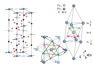
Important symmetry restrictions on the DM vector have been discussed since it was initially introduced more than fifty years ago Dzyaloshinskii57 ; Dzyaloshinskii58 ; Moriya60a ; Moriya60b . In the case of FeBO3, with crystal symmetry , there are two iron atoms at the inversion centres, two boron atoms at the positions, and six oxygens at sites. If the oxygen atoms were absent, or positioned exactly between two neighbouring iron atoms, the symmetry would be , which does not allow the DM interaction. It is therefore the small displacement of oxygen atoms, striving towards a close-packed structure, that drives iron borate into the observed complex magnetic ordering pattern. A closer examination of the FeBO3 crystal structure (Fig. 1) reveals that each Fe atom is connected to six equivalent nearest Fe neighbours: three in the plane above and three below. The six DM vectors linking these Fe atoms are related by symmetry and when summed, lead to a resultant vector along . It follows from equation (1) that the DM vector of this type induces a twist between and spins in the plane, but the symmetry alone cannot say whether this twist will be left-handed or right-handed. The absolute sign of local twist can be found both experimentally and theoretically using techniques described in the following text.
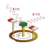
The present experimental technique relies on the fact that the weak ferromagnetic moment is perpendicular to the opposing antiferromagnetic (AF) components (Fig. 1) . Since the former can be turned with a small external field (Fig. 2), the dominant AF structure is ‘dragged’ around to follow it, offering a powerful new method to manipulate the magnetic x-ray diffraction. In order to determine the sign of the DM interaction, we must determine whether the rotation of spins is in the same sense as the rotation of the oxygen triangles, or opposite. Unfortunately, the standard techniques for characterising antiferromagnetic structures - x-ray or neutron diffraction - do not help: The sign of the twist appears in the of the diffracted wave, which is lost in an intensity measurement - an aspect of the famous ‘phase problem’ of crystallography. Borrowing from the ideas behind holography, it was recently suggested by some of usDmitrienko2010 that the sign of the DM vector could be measured with resonant x-ray diffraction by observing interference between the resonantBlume94 and magneticdeBergevin1981 scattering amplitudes. The resonant scattering process adopted is a rather exotic one, involving pure electric quadrupole events (i.e. beyond the usual dipole approximation). Its phase and amplitude vary rapidly with photon energy, being significant only very close the the Fe x-ray absorption edge energy of 7.11 keV, and it has a complex dependence on both photon polarization and the rotation of the sample about the normal to the diffracting planes (-angle). However, in recent years, such phenomena have been studied in detail and are now extremely well understood Dmitrienko1 ; Lovesey1 . Moreover, both the resonant and magnetic scattering signals appear at the same Bragg reflection positions - - that are ‘forbidden’ for the vastly stronger charge scattering processes, and have comparable amplitudes to each other, maximizing the effects of interference. The sign and amplitude of the magnetic scattering signal depends on the spin direction, which can be rotated with a magnetic field. We thus expect control of the amplitude and phase of both the magnetic scattering and resonant reference wave, allowing the phase of the magnetic scattering to be determined. Details of the magnetic and resonant scattering amplitudes are given in SI.
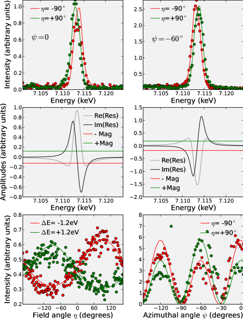
Three types of measurement are presented. The first shows a remarkable effect - an apparent jump in the energy of the resonant scattering peak as the magnetic motif is rotated by 180∘, as a result of constructive (destructive) interference to the low (high) energy side of the resonance (Fig. 3) . The opposite jump was observed when the phase of the resonant scattering was reversed by changing the sample angle. Both jumps are reproduced by our ab initio calculations, which make a definite prediction for the sign of the DM interaction, the phase of the magnetic scattering amplitude, and thus the direction of the jump. The second measurement shows the intensity, measured as a continuous rotation of the field angle, for the low and high energy side of the resonance. For the final measurement, the sample azimuthal angle was varied continuously, with a fixed photon energy and field applied in two orthogonal directions. In all cases, the phase of the magnetic scattering, who’s reversal would convert red to green lines and vice versa were consistent, completely unambiguous, and in agreement with the calculations.
One of the main goals of the present work is to demonstrate that the sign of the DM interaction can be determined reliably not only by experiment but also theoretically. To this end we have performed first-principles calculations by using Local Density Approximation incorporating the on-site Coulomb interaction U and the Spin-Orbit coupling (LDA+U+SO) shorikov-lda-u-so ; solovyev-lda-u-so . Our calculations predict (see SI) that the lowest energy stable magnetic structure is precisely the one observed experimentally and shown in Fig. 1. Furthermore, we predict that the magnetic twist between adjacent layers is in the same direction as the twist of the oxygen triangles. This is the basis for the calculated curves in Fig. 3 , and is thus very clearly confirmed by experiment.
Since the vector product in equation (1) is parallel to z-axis, and the corresponding DM interaction must reduce the energy of the system, we can deduce that is negative. The absolute value of the DM interaction energy is readily estimated from the measured canting angle (0.9∘) and isotropic exchange interaction: = 0.33 meV. Here is approximately 10.3 meV.
The determination of the and parameters with account of hybridization, correlation, temperature and spin-orbit coupling effects is a complex methodological and computational problem requiring a whole arsenal of numerical techniques Moriya60b ; solovyev-lamno3 ; aharony ; mazurenko-fe2o3 . Here, we outline a second, and very general next-generation method that has a simple formulation and captures all important electronic and magnetic excitation effects katsnelson . The resulting expression for the correlated band DM interaction can be applied to a wide range of materials and is given by
| (2) |
where is the the energy-integrated inter-site Green’s function which describes the propagation of an electron from site to , is the total moment operator, is the hopping matrix and represents an anticommutator (see SI §IV for details). The method is developed in a many-body form, thus, the state-of-the-art numerical approaches such as dynamical mean-field theory can be used to take into account temperature and dynamical Coulomb correlations effects.
The calculated DM vector linking iron atoms 0 and 1 (Fig. 1) , for example, is =(-0.249, 0, -0.240) meV. By symmetry, it lies in the plane, perpendicular to the two-fold axis that passes through the oxygen atomMoriya60b . All six symmetrically-equivalent vectors have the same component, but the components average to zero. Our calculated canting angle of 0.7∘ is only slightly smaller than experimental value of 0.9∘, used for the self-consistent calculation.
Crucially, the sign of the DM interaction, which we have predicted by two theoretical methods, determines the direction of twist of the magnetic structure, which affects the phase of the magnetic scattering and the sign of the interference term in Fig. 3. It is thus confirmed unambiguously by the experimental data.
In conclusion, we show that a new interference technique in which measurements are carried out with precise control of the amplitude and phase of a reference wave gives an unambiguous result for the sign of the Dzyaloshinskii-Moriya interaction. We find that the twist in the magnetic structure is in the same direction as that of the oxygen atoms. The results prove the efficacy of state-of-the-art electronic structure calculations, able to predict the magnetic ground-state and both direction and strength of the DM interaction. These findings take us a step closer to realising the prediction of complex non-collinear magnetic structures and the associated properties of an important class of materials that includes weak ferromagnets and multiferroics.
Experimental Method
The experiments were mostly carried out at beamline BM28 (XMaS), European Synchrotron Radiation Facility BM28 , with preliminary investigations of the pure magnetic and pure resonant scattering carried out at beamline I16, Diamond Light Source I16 (See SI). Both beamlines provide intense x-ray beams covering the required energy range ( keV), focussed onto a 10-800K cryofurnace, mounted at the centre of large six-circle diffractometers. The sample - a single crystal of FeBO3 mm3 in size - was attached with its 001 surface normal to the diffractometer rotation axis BM28 , which was parallel to the azimuthal rotation axis, (Fig. 2). Two small rare-earth magnets provided a magnetic field of 0.011 T, sufficient to saturate the weak ferromagnetism within the crystal plane, with an orientation determined by the motorized rotation angle of the magnets around the axis. Scattering was in the vertical plane, perpendicular to the linearly ()-polarized incident beam, and a linear polarization analyser, based on a Cu 220 Bragg reflection, selected just the rotated () polarization channel. Most measurements were carried out at temperature T=200K where the moments are close to saturation, with subsidiary measurements performed at T=400K (well above the magnetic ordering temperature of 348 K) where the magnetic scattering is absent.
Figure Legends
References
- (1) Eerenstein, W., Mathur N. D. and Scott, J. F. Multiferroic and magnetoelectric materials. Nature 442, 759–765 (2006).
- (2) Cheong, S.-W. and Mostovoy, M. Multiferroics: a magnetic twist for Ferroelectricity. Nature Mater. 6, 13–20 (2007).
- (3) Rößler, U. K., Bogdanov A. N. and Pfleiderer C. Spontaneous skyrmion ground states in magnetic metals. Nature 442, 797–801 (2006).
- (4) Yu, X. Z. et al. Real-space observation of a two-dimensional skyrmion crystal. Nature 465, 901–904 (2010).
- (5) Dzialoshinskii, I. E. Thermodynamic theory of ”weak” ferromagnetism in antiferromagnetic substances. Sov. Phys. JETP 5, 1259–1262 (1957).
- (6) Dzyaloshinsky, I. A thermodynamic theory of “weak” ferromagnetism of antiferromagnetics J. Phys. Chem. Solids 4, 241–255 (1958).
- (7) Moriya, T. New mechanism of anisotropic superexchange interaction Phys. Rev. Lett. 4, 228–230 (1960).
- (8) Moriya, T. Anisotropic superexchange interaction and weak ferromagnetism. Phys. Rev. 120, 91–98 (1960).
- (9) Kitzerow, H.-S. and Bahr, C. (Eds.) Chirality in Liquid Crystals (Springer, New York, 2001).
- (10) Blundell, S. Magnetism in condensed matter (Oxford University Press, Oxford, 2001).
- (11) White R. (Ed.) Quantum theory of magnetism (Springer, New York, 2007).
- (12) Matarrese, L. W. and Stout, J. W. Magnetic Anisotropy of NiF2 Phys.Rev. 94, 1792–1793 (1954).
- (13) Dmitrienko, V. E. Ovchinnikova, E. N., Kokubun, J. and Ishida, K. Dzyaloshinskii–Moriya Interaction: How to Measure Its Sign in Weak Ferromagnets? JETP Lett. 92, 383–387 (2010).
- (14) Blume, M. Resonant Anomalous X-Ray Scattering, (Materlik, G., Sparks, C. S. and Fischer, K. Eds.) (North-Holland, Amsterdam, 1994).
- (15) de Bergevin, F. and Brunel, M. Diffraction of X-rays by Magnetic Materials. I. General Formulae and Measurements on Ferro- and Ferrimagnetic Compounds Acta Cryst. A 37, 314–324 (1981).
- (16) Dmitrienko, V.E., Ishida, K., Kirfel, A. and Ovchinnikova, E. N. Polarization anisotropy of X-ray atomic factors and ‘forbidden’ resonant reflections Acta Cryst A 61 481–493 (2005).
- (17) Lovesey, S. W., Balcar, E., Knight, K. S., Rodríguez, J. F. Electronic properties of crystalline materials observed in X-ray diffraction Phys. Rep. 411, 233–289 (2005).
- (18) Solovyev, I. V., Lichtenstein, A. I., Terakura, K. Is Hund’s Second Rule Responsible for the Orbital Magnetism in Solids? Phys. Rev. Lett. 80, 5758–5761 (1998).
- (19) Shorikov, A. O., Lukoyanov, A. V., Korotin, M. A. and Anisimov, V. I. Magnetic state and electronic structure of the and phases of metallic Pu and its compounds Phys. Rev. B 72, 024458 (2005).
- (20) Mazurenko, V. V. and Anisimov, V. I. Weak ferromagnetism in antiferromagnets: -Fe2O3 and La2CuO4 Phys. Rev. B 71, 184434 (2005).
- (21) Yildirim, T., Harris, A. B., Aharony, A. and Entin-Wohlman, O. Anisotropic spin Hamiltonians due to spin-orbit and Coulomb exchange interactions Phys. Rev. B 52, 10239-10267 (1995).
- (22) Solovyev, I., Hamada, N. and Terakura, K. Crucial Role of the Lattice Distortion in the Magnetism of LaMnO3 Phys. Rev. Lett. 76, 4825–4828 (1996).
- (23) Katsnelson, M. I., Kvashnin, Y. O., Mazurenko, V. V. and Lichtenstein, A. I. Correlated band theory of spin and orbital contributions to Dzyaloshinskii-Moriya interactions Phys. Rev. B 82, 100403 (2010).
- (24) Brown, S. D. et al. The XMaS beamline at ESRF: instrumental developments and high resolution diffraction studies J.Synchrotron Rad., 8, 1172–1181 (2001).
- (25) Collins, S. P. et al. Diamond Beamline I16 (Materials & Magnetism) AIP Conf. Proc., 1234 303–306 (2009).
Acknowledgments
The work of VVM is supported by the grant program of President of Russian Federation MK-5565.2013.2, the contracts of the Ministry of education and science of Russia N 14.A18.21.0076 and 14.A18.21.0889. VED is grateful for the grant of Presidium RAS “Diffraction of synchrotron radiation in multiferroics and chiral magnetics”. MIK acknowledges a financial support by FOM (The Netherlands). We thank the staff of ESRF BM-28 for expert assistance, and Yuri Shvyd’ko for the loan of the FeBO3 crystal.
Twisted magnetic patterns:
Exploring the Dzyaloshinskii–Moriya vector
Supplementary Information
I Pure Magnetic Scattering from Iron Borate
The primary result of the present study is to determine the phase of magnetic x-ray scattering from FeBO3, by observing interference with resonant forbidden scattering, from which the sign of the Dzyaloshinskii-Moriya (DM) interaction can be determined and compared to new theoretical models. In order to carry out such an analysis with confidence, it is necessary to establish that the pure magnetic and pure resonant signals can be modelled reliably and accurately, with a particular emphasis on their phases. We begin by discussing the theoretical and experimental forms of the magnetic scattering.
Quantum or semi-classical electrodynamical calculations give a well established expression for the amplitude of spin magnetic x-ray scattering SIdeBergevin1981 ; SIBlume1985 ; SILovesey1996
| (3) |
where is the scattering vector, vector is the corresponding Fourier harmonic of the spin (not magnetic moment!) density, is the classical electron radius, is the photon energy and vector determines polarization properties of spin scattering:
| (4) |
Here () and () are the polarization and wave vectors of the incident (scattered) waves, , . The sign of this expression is positive if the x-ray plane wave is written as . The (negative) sign of the scattering electronic charge, , is not important because the scattering amplitude depends only on . For and polarizations (linear polarization perpendicular and parallel to the scattering plane, ) and polarization states expressed as column vectors, can be written as
| (5) |
It is important to note that the non-resonant magnetic scattering has both a non-rotated () and a rotated () component. Only the latter will play a role in interference because the resonant scattering has only this component. The orbital contribution to non-resonant magnetic scattering is expected to be small for iron in FeBO3 (confirmed both by our experimental data and ab initio simulations) and will be neglected for the time being.
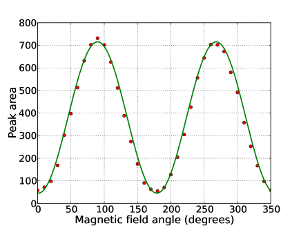
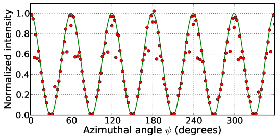
In weak ferromagnets of FeBO3 type, the direction of for the pure antiferromagnetic reflections is normal to the threefold axis and to the direction of the external magnetic field (applied in the easy plane). There are only two iron atoms per unit cell and the magnetic structure factor of forbidden reflections (i.e. reflections of the form , which are completely forbidden by spacegroup selection rules for isotropic scattering) has a simple form: where is the total spin of iron atom and is the spin form factor. If the spin structure factor is real (for instance for centrosymmetric structures) then the magnetic scattering amplitude is purely imaginary. The sense (sign) of is determined by the sign of the average Dzyaloshinskii-Moriya vector and by direction of the magnetic field . Vector can be rotated in the easy plane by rotation of as long as is strong enough to overcome the in-plane magnetocrystalline anisotropy (in the plane).
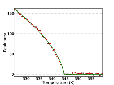
Measurements of the pure magnetic (003) reflection vs magnetic field angle were carried out at Beamline I16, Diamond Light Source SII16 , at an energy of 5.1 keV, chosen to be far from the iron -edge resonance and free from multiple scattering artefacts. The results, shown in Fig. 4, reveal data of spectacularly high quality due to that fact that no sample rotation is required for this new type of measurement. Moreover, the data agree extremely well with the calculated intensity (to within a single scaling parameter) based on the above expressions, confirming the negligible contribution from orbital magnetism. Magnetic scattering measurements were carried out at ambient temperature, well below the ordering temperature of T 348 K. On heating the sample in a closed-cycle cryofurnace, the magnetic scattering intensity followed the expected form of a second-order phase transition (Fig. 5), reported in the literature SIEicschutz1970 .
II Pure Quadrupole Resonant Scattering from Iron Borate
The charge scattering amplitude consists of two parts: non-resonant Thomson scattering and resonant scattering. The latter is traditionally called ‘anomalous’ scattering:
| (6) |
where scalar is the structure factor of the electron density and tensor is the structure factor of resonant scattering. The tensorial properties of are especially pronounced near absorption edges SIFinkelstein where the resonant atomic factors reflect the symmetry of corresponding atomic positions, the shape and orientation of chemical bonds etc. For forbidden reflections because scalar scattering of two (or more) equivalent atoms in the unit cell cancels exactly, whereas can be non-zero because the tensor atomic factors of those equivalent atoms can be different if the atoms are related by screw-axes or glide mirror planes, i.e. they are oriented differently.
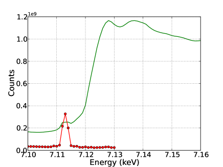
A symmetry analysis of the resonant scattering tensor SIDmitrienko1 ; SILovesey1 from the iron sites in FeBO3 reveals that, for forbidden reflections of the form , the lowest order contributing tensor is of rank four, which can arise from pure electric quadrupole transitions. Since transitions of this kind, into the relatively narrow 3 band, tend to be reduced in energy due to differences in core-hole screening, one might expect a very sharp resonance just below the Fe edge. This is precisely what was observed and is shown in Fig. 6, with experimental data taken again at Diamond I16. That the tensorial (geometrical) properties of the resonant scattering are as expected can be confirmed by measuring the (003) resonant Bragg peak as a function of the sample azimuthal () rotation, and comparing with the calculated angle dependence. While multiple scattering events inevitable appear as ‘noise’ in such a measurement, the results indicate very good agreement with the calculations and give confidence in the physical interpretation of the scattering process.
The resonant scattering energy spectrum shows, to a first approximation, a single resonance. However, modelling the scattered intensity with the FDMNES program SIJoly01 reveals an energy dependence that is slightly better described by two nearby resonances. The FDMNES results, verified by the experimental data, provide a valuable tool to describe the resonant scattering.
It is interesting to note that, while weak ferromagnetism and resonant forbidden diffraction are each relatively rare, there appears to be a very strong tendency for the former to exhibit the latter. This can be understood qualitatively by the fact they both phenomena rely on a twisted local environment of heavy atoms.
III Theory: FDMNES and scattering phases
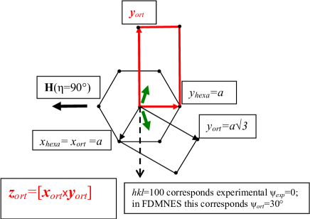
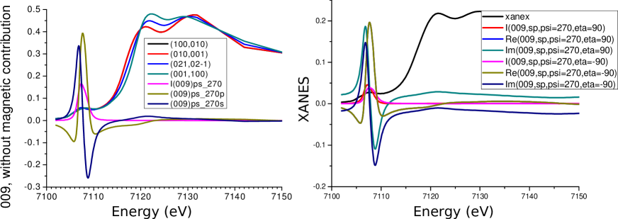
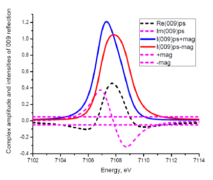
Most crucial for the present study is the relative phase between the resonant charge and magnetic scattering terms, determined by the structure factors and . The magnetic term was calculated according to Eq. 3 and for resonant scattering amplitude we used the FDMNES program (see Fig. 8 for some important definitions) as outlined above. Fig. 9 shows the calculated absorption and scattering amplitudes with various azimuthal and field angles, while in Fig. 10 we highlight the real and imaginary parts of the resonant structure factor in the pre-edge region just below the Fe -edge (black and magenta dotted lines correspondingly) and show how the intensity peak shifts down or up in energy due to interference with the positive or negative magnetic scattering amplitude. We see that a modest non-resonant magnetic scattering produces a pronounced difference in reflection intensities owing its interference with the imaginary part of the resonant scattering. The most important aspect of the calculated magnetic/resonance interference is that we observe a clear energy jump which determines the phase of the magnetic scattering elegantly and unambiguously.
Let us assume (as predicted by the present theory) that the DM interaction induces a small left-hand twist of opposing spins of atoms at (0,0,0) and (1/2,1/2,1/2). This means that in the DM energy, , vector is directed opposite to (opposite to ). (Note that the magnetic moment is opposite to the spin direction since is negative). In Fig. 8 , for the indicated direction of , the magnetic moment of the atom at (0,0,0) is directed up and slightly left whereas for the atom at (1/2,1/2,1/2) the magnetic moment is directed down and slightly left. Correspondingly, the spin of the atom at (0,0,0) is directed down and slightly right whereas for the atom at (1/2,1/2,1/2) its spin is directed up and slightly right (shown by short green arrows). For the opposite direction of all the moments and spins change sign. The conventional orthorhombic unit cell (used in FDMNES) is shown as black rectangle. Experimental azimuthal angle =0 corresponds, in FDMNES, to (dashed arrow); for , .
It is convenient to rotate the orthogonal axes to an equivalent orientation so that will be vertical (red rectangle). In this case the spin of the atom at (0,0,0) is directed along - whereas for the atom at (1/2,1/2,1/2) it is directed along , so that the spin structure factor is proportional to -. Now, for the FDMNES azimuthal angle or .
The FDMNES amplitudes are calculated for small cluster of radius 4.0 Å, containing 33 atoms. We find that the size of the cluster and the method of calculation (Green’s function or finite difference method) are not crucial for the important details of quadrupole-quadrupole scattering, either in amplitude or sign. The sign of the non-resonant magnetic scattering in FDMNES is given by , where B is the vector of the non-resonant spin scattering. , giving . For Thomson scattering FDMNES gives correctly with and . (Note that, the magnetic scattering intensity in Fig. 4 does not go exactly to zero because the data correspond to the total scattering intensity , whereas we consider here only the rotated () polarization channel that takes part in interference.)
IV Theory: Electronic Structure Calculations
To simulate the electronic structure and magnetic properties of iron borate in the ground state we used the tight-binding linear-muffin-tin-orbital atomic sphere approximation (TB-LMTO-ASA) method SItb-lmto in terms of local spin density approximation, taking into account Hubbard U (LSDA+U) SIldau-Anisimov91 and spin-orbit coupling (LDA+U+SO) SIshorikov-lda-u-so . The crystal structure data were taken from the literature SIdiehl . The radii of atomic spheres have been set to r(Fe)= 1.45 Å, r(B)= 0.74 Å and r(O)= 0.85 Å. In order to fill the interstitial space in the unit cell the required number of empty spheres was added.
Previous theoretical investigations aiming at the description of the insulating state of iron borate demonstrated that the choice of the on-site Coulomb interaction, U plays an important role in reproducing the correct value of the bandgap of 2.8 eV SIfebo3-band-gap1 ; SIfebo3-band-gap2 . Depending on the method the value of the U parameter varies from 2.97 eV (many-body model calculations) to 7 eV (first-principles calculations) SIfebo3-ovchinnikov ; SIfebo3-ggau . In the present work we focus on the correct description of the magnetic couplings between iron moments and the value of the canting angle observed in experiment. As we will show below, good agreement can be achieved with U=5 eV. The same value was used to reproduce the electronic and magnetic structure of haematite (-Fe2O3) – another classical example of antiferromagnet with weak ferromagnetism SImazurenko-fe2o3 .
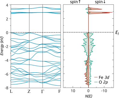
Fig. 11 gives the band structure and partial densities of states (DOSs) calculated using the LSDA+U approach for antiferromagnetic (AFM) configuration (without spin canting). The electronic spectrum agrees with that presented in previous works SIfebo3-ggau . One can see that the unoccupied bands above the Fermi level demonstrate localized behaviour. They mainly originate from the iron 3 states. This is not the case for valence band where a strong hybridization of the 3 iron and 2 oxygen states is observed. The LSDA+U value of the energy gap of 2.7 eV is in excellent agreement with experimental value.
The previous ab-initio investigations SIfebo3-ggau revealed two possible magnetic solutions with high-spin and low-spin ground states. In our calculations we can reproduce both of them by varying the value of the initial spin splitting for the on-site LSDA+U potential. The resulting magnetic moments are = 4.28 for high-spin () and = 1.1 for low-spin ) states. Below we will consider the high-spin solution which is the ground state at ambient conditions (and corresponds to experimental data). The calculations performed for the ferromagnetic configuration of iron moments demonstrate a finite magnetization of the oxygen atoms ( 0.2 ), which is another manifestation of a strong hybridization between iron and oxygen states.
V Theory: Isotropic Magnetic Coupling
Having described the antiferromagnetic ground state without spin-orbit coupling we are going to analyse the low-energy magnetic excitation spectrum of the system to obtain information about isotropic exchange (IE) interactions for the Heisenberg Hamiltonian, i.e. the first term in Eq. (1)(main text). For this purpose, one can use a magnetic force theorem that, being formulated in terms of Green’s functions, have produced an array of very reliable results concerning magnetic couplings in transition metal oxides SIsolovyev-mno ; SImazurenko-na2v3o7 . Starting from the collinear ground state the exchange interaction parameters are determined via calculation of second variation of total energy for small deviation of magnetic moments, . The advantage of this method is that the expression for the second derivative can be derived analytically and requires for its evaluation only calculation of the integral over the product of the one-electron Green’s functions.
The isotropic exchange interactions between magnetic moments calculated for U= 5 eV are presented in Table 1. It shows that there is a strong interaction of the central site and iron atoms that belong to the first coordination sphere. The couplings with next nearest neighbours are at least of one order of magnitude smaller and we can neglect them. The leading magnetic interaction of 10.3 meV is in good agreement with experimental estimate of 7.5 meV in SImoessbauer-febo3 . These results, obtained with the magnetic force theorem, can be confirmed by the total energy difference method where the exchange interaction defined SIexch-via-diff as . Here () is energy of the ferromagnetic (antiferromagnetic) configuration and is a number of nearest neighbours. We obtain =9 meV, which is in good agreement with the Green’s function method results.
| Fe(1) | Fe(2) | Fe(3) | Fe(4) | Fe(5) | Fe(6) | Fe(7) |
|---|---|---|---|---|---|---|
| 10.28 | 0.21 | 0 | 0.54 | -0.08 | 0 | 0.02 |
VI Theory: Modeling the canted state
The experimental investigations revealed that in the ground state there is a canting of the magnetic moments with respect to the antiferromagnetic configuration. The value of the canting of 0.96∘ is one order of magnitude larger than that observed in other antiferromagnets with weak ferromagnetism such as Fe2O3 and La2CuO4 SImazurenko-fe2o3 . To describe this non-collinear magnetic state we performed LDA+U+SO SIshorikov-lda-u-so calculations that incorporate spin-orbit coupling. The latter leads to an orbital magnetism and is responsible for magnetocrystalline single-site anisotropy and Dzyaloshinskii-Moriya interactions between magnetic moments. Depending on initial directions of the magnetic moments in our calculations we simulated different magnetic configurations. Two stable magnetic states, with moments lying along and axes, were obtained. The main difference between these solutions is that we observe a canting of the spins when moments are lying in the plane (Table 2). This is not the case for -oriented configurations where they are strictly antiparallel. The LDA+U+SO value of the canting angle, = 0.96∘ is in excellent agreement with the experimental estimate. The energy difference between - and -type magnetic configurations meV indicates that the non-collinear canted configuration corresponds to the minimum of the system energy.
| Fe() | moment | ex | ey | ez |
|---|---|---|---|---|
| A | = 4.249 | -0.999 | -0.016 | 0 |
| = 0.027 | -0.999 | -0.017 | 0 | |
| B | = 4.249 | 0.999 | -0.016 | 0 |
| = 0.027 | 0.999 | -0.017 | 0 |
Using the calculated magnetic moments (Table II) we can obtain the sign and value of some components of the Dzyaloshinskii-Moriya interaction in the Hamiltonian given by Eq. 1 (main text). Since the vector product is parallel to z-axis, the corresponding anisotropic coupling must be antiparallel in order to minimize the energy of the system, i.e., . As for the absolute value of the DM interaction, it can be estimated via canting angle and isotropic exchange interaction, = 0.33 meV. Here = 10.3 meV, the isotropic exchange interaction of the Fe atom with the nearest neighbours. Thus the estimated z-component of the DM interaction can be associated with the individual antisymmetric exchange interaction of the 0th site with atoms belonging the first coordination sphere.
VII Theory: Correlated Band Method for calculating the Dzyaloshinskii-Moriya parameters
Here, we present a second, and very general, method for the calculation of individual DM interactions.
There are two important methodological steps in our approach. First, we consider the effect of the local rotations
of the total
angular momentum
operator,
, on the inter-site (hopping) part
of the Hubbard Hamiltonian with rotationally invariant form of the Coulomb interaction, .
The second step is to integrate out the fermionic degrees of freedom in the expression for the variation of the total energy.
This is an adiabatic approximation SIantropov where we assume that the spin dynamics with the typical energy scale varying from 0.05 meV
(DM interaction) to 10 meV (isotropic exchange interaction) is much slower than the electronic processes with characteristic energies of intra-atomic exchange or bandwidth (1 eV).
The actual time scales of spin and electronic processes in a particular strongly correlated system are accessible with advanced experimental techniques.
In this respect an important information about spin dynamics in FeBO3 due to the ultrafast laser impulse was
reported in the literature SIRasing1 ; SIRasing2 .
The resulting variation of the electronic Hamiltonian has a very compact form and contains the Dzyaloshinskii-Moriya interaction (anticommutator) and symmetric anisotropic exchange interaction (commutator),
| (7) |
where is the energy-integrated inter-site Green’s function (occupation matrix) which describes the propagation of an electron from site to , is the total moment operator and is the hopping matrix. Being formulated in the Wannier function basis this approach naturally takes into account the hybridization between metal and ligand atoms of the strongly correlated system - important for simulation of itinerant magnets where there is a strong delocalization of the magnetic moment. All matrices are in spinorial form and corresponding spin and orbital indices are omitted. From Eq. (7) one clearly sees that DM interaction is an antisymmetric interaction of kinetic origin. The use of the total angular momentum operator allows us to probe the spin and orbital structure of the hopping matrix.
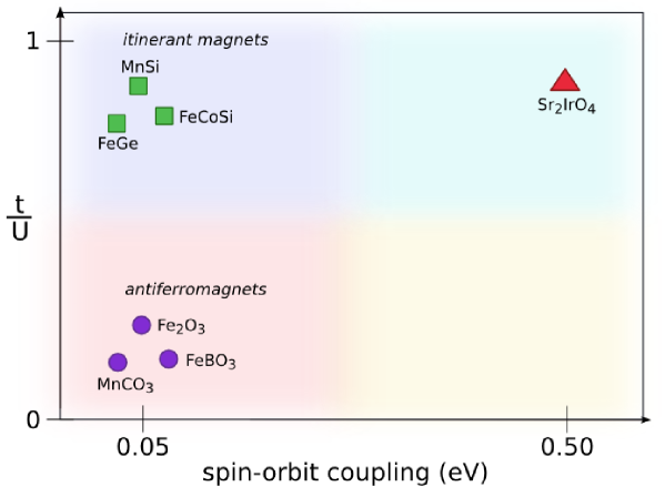
In contrast to other numerical approaches SImazurenko-fe2o3 ; SIsolovyev-lamno3 ; SIrudenko for calculating DM interaction which are based on the rotation of the on-site exchange fields, our method has fully inter-site formulation (i.e. the rotation of the hopping matrix). For the case of orbitally-independent magnetic excitations the on-site and inter-site considerations provide two alternative ways to solve the problem of the determination of spin Hamiltonian parameters. On the other hand our inter-site approach becomes preferable when the potential depends on the particular orbital, and spin-orbit coupling is taken into account. In this case the ‘on-site’ formulation leads to a complicated situation where, in general, the spins of different orbitals can be noncollinear to each other (intra-atomic noncollinear magnetic ordering) SIantropov , requiring the spin dynamics for different orbital states to be treated independently at one site. In turn, such an orbital resolution complicates the resulting magnetic model that will also have orbital degree of freedom. As we previously demonstrated SIkatsnelson our inter-site consideration allows one to preserve the simplicity of the magnetic model while taking into account orbital and spin excitations of the system. Thus, the correlated band method for calculating DM interaction parameters can be used for a wide range of materials (Fig. 12) with different strengths of the spin-orbit coupling and correlation effects.
For FeBO3, the calculated anisotropic exchange interactions between atom and atoms that belong to the first coordination sphere (Fig. 1, main text) are presented in Table 3. They are not independent and can be transformed to each other by using the symmetry operations of the space group . For instance, the transformation from the bond 0-1 to 0-2 corresponds to the rotation on 120∘ around x-axis. Such an operation changes neither the z-component of the position vector nor the Dzyaloshinskii-Moriya vector. There is also an inversion centre at the 0th site, which means that the following relations are satisfied, , and . From Table 3 one can see that our numerical method reproduces these relations with a good accuracy and that the sum of all DM vectors lies along the three-fold axis, . Moreover, the sign of DMI fully corresponds to the canted ground state of FeBO3 obtained in LDA+U+SO calculations.
| Bond | (meV) | |
|---|---|---|
| 0-1 | (1.0 ; 0.0 ; -0.9044) | (-0.249; 0.0; -0.240) |
| 0-2 | (-0.5 ; - ; -0.9044) | (0.124 ; 0.216 ; -0.240) |
| 0-3 | (-0.5 ; ; -0.9044) | (0.124 ; -0.216 ; -0.240) |
| 0-4 | (-1.0 ; 0.0 ; 0.9044) | (-0.249; 0.0 ; -0.240) |
| 0-5 | (0.5 ; - ; 0.9044) | (0.124 ; -0.216 ; -0.240) |
| 0-6 | (0.5 ; ; 0.9044) | (0.124 ; 0.216 ; -0.240) |
Having calculated all the parameters of the spin Hamiltonian we are in position to describe the weak ferromagnetism observed in iron borate. For this purpose, one should define the canting angle and the plane of the spin rotation, , which can be done in the mean-field approximation,
| (8) |
Here the summation runs over the atoms that belong to the first coordination sphere. The symmetry of the canting is defined by the symmetry of the magnetic torque, i.e. the summary DMI. In our case the latter is along axis, which means the rotation of the spins occurs in the plane. The value of calculated this way is equal to 0.7∘, which is only slightly smaller than the value obtained above by self-consistent calculation and the experimental value of 0.9∘.
References
- (1) de Bergevin, F. and Brunel, M. Diffraction of X-rays by Magnetic Materials. I. General Formulae and Measurements on Ferro- and Ferrimagnetic Compounds Acta Cryst. A 37, 314–324 (1981).
- (2) Blume, M. Magnetic scattering of x rays J.Appl.Phys 57, 3615-3618 (1985).
- (3) Lovesey, S. and Collins, S. P. X-ray Scattering and Absorption by Magnetic Materials (Clarendon Press, Oxford, 1996).
- (4) Collins, S. P., et al. Diamond Beamline I16 (Materials & Magnetism) AIP Conf. Proc., 1234 303–306 (2009).
- (5) Eibschütz, M., Pfeiffer, L. and Nielsen J. W. Critical–Point Behavior of FeBO3 Single Crystals by Mössbauer Effect J. Appl.Phys. 41, 1276–1277 (1970).
- (6) Finkelstein, K. D. Shen, Q. and Shastri, S. Resonant Diffraction near the Iron Edge in -Fe2O3 Phys. Rev. Lett. 69 1612–1615 (1992).
- (7) Dmitrienko, V. E., Ishida, K., Kirfel, A. and Ovchinnikova, E. N. Polarization anisotropy of X-ray atomic factors and ‘forbidden’ resonant reflections Acta Cryst A 61 (2005) 481–493 .
- (8) Lovesey, S. W., Balcar, E., Knight, K. S., Rodríguez, J. F. Electronic properties of crystalline materials observed in X-ray diffraction Phys. Rep. 411, 233–289 (2005).
- (9) Joly, Y. X-ray absorption near-edge structure calculations beyond the muffin-tin approximation Phys. Rev. B 63, 125120 (2001).
- (10) Andersen, O. K. and Jepsen, O. Explicit, First-Principles Tight-Binding Theory Phys. Rev. Lett. 53, 2571–2574 (1984).
- (11) Anisimov, V. I., Zaanen, J. and Andersen, O. Band theory and Mott insulators: Hubbard U instead of Stoner I Phys. Rev. B 44, 943–954 (1991).
- (12) Shorikov, A. O., Lukoyanov, A. V., Korotin, M. A. and Anisimov, V. I. Magnetic state and electronic structure of the and phases of metallic Pu and its compounds Phys. Rev. B 72, 024458 (2005).
- (13) Diehl, R. Crystal structure refinement of ferric borate, FeBO3 Sol.Stat.Comm. 17, 743–745 (1975).
- (14) Wolfe, R., Kurtzig, A. J. and Lecraw, R. C. Room Temperature Ferromagnetic Materials Transparent in the Visible J.Appl.Phys. 41, 1218–1224 (1970).
- (15) Edelman, I. S., Seleznev, V. N., Vasileva, T. I. and Malakhov, A. V. Optical properties of FeBO3 in the strong absorption region Fizika Tverdogo Tela 14, 2810-2813 (1972).
- (16) Ovchinnikov, S. and Zabluda, V. The Energy Band Structure and Optical Spectra of FeBO3 Calculated with Allowance for Strong Electron Correlations Journal of Experimental and Theoretical Physics 98, 135–143 (2004).
- (17) Shang, S. et al. Band structure of FeBO3: Implications for tailoring the band gap of nanoparticles Appl.Phys.Lett. 91, 253115–253117 (2007).
- (18) Mazurenko, V. V. and Anisimov, V. I. Weak ferromagnetism in antiferromagnets: -Fe2O3 and La2CuO4 Phys. Rev. B 71, 184434 (2005).
- (19) Solovyev, I. V. and Terakura, K. Effective single-particle potentials for MnO in light of interatomic magnetic interactions: Existing theories and perspectives Phys. Rev. B 58, 15496–15507 (1998).
- (20) Mazurenko, V. V., Mila, F. and Anisimov, V. I. Electronic structure and exchange interactions of Na2V3O7 Phys. Rev. B 73, 014418 (2006).
- (21) Eibschütz, M. and Lines, M. E. Sublattice Magnetization of FeBO3 Single Crystals by Mössbauer Effect Phys. Rev. B 7, 4907–4915 (1973).
- (22) Moreira, Ibério de P. R. and Illas, F. Ab initio theoretical comparative study of magnetic coupling in KNiF3 and K2NiF4 Phys. Rev. B 55, 4129–4137 (1997).
- (23) Antropov, V. P. et al. Spin dynamics in magnets: Equation of motion and finite temperature effects Phys. Rev. B 54 1019–1035 (1996).
- (24) Kalashnikova, A. M. et al. Impulsive Generation of Coherent Magnons by Linearly Polarized Light in the Easy-Plane Antiferromagnet FeBO3 Phys. Rev. Lett. 99, 167205 (2007).
- (25) Kimel, A. V., Pisarev, R. V., Hohlfeld, J. and Rasing, Th. Ultrafast Quenching of the Antiferromagnetic Order in FeBO3 : Direct Optical Probing of the Phonon-Magnon Coupling Phys. Rev. Lett. 89, 287401 (2002).
- (26) Solovyev, I., Hamada, N. and Terakura, K. Crucial Role of the Lattice Distortion in the Magnetism of LaMnO3 Phys. Rev. Lett. 76, 4825–4828 (1996).
- (27) Rudenko, A. N., Mazurenko, V. V., Anisimov, V. I. and Lichtenstein, A. I. Weak ferromagnetism in Mn nanochains on the CuN surface Phys. Rev. B 79 144418 (2009).
- (28) Katsnelson, M. I., Kvashnin, Y. O., Mazurenko, V. V. and Lichtenstein, A. I. Correlated band theory of spin and orbital contributions to Dzyaloshinskii-Moriya interactions Phys. Rev. B 82, 100403 (2010).