Towards the Asymptotic Sum Capacity of the MIMO Cellular Two-Way Relay Channel
Abstract
In this paper, we consider the transceiver and relay design for the multiple-input multiple-output (MIMO) cellular two-way relay channel (cTWRC), where a multi-antenna base station (BS) exchanges information with multiple multi-antenna mobile stations via a multi-antenna relay station (RS). We propose a novel two-way relaying scheme to approach the sum capacity of the MIMO cTWRC. A key contribution of this work is a new non-linear lattice-based precoding technique to pre-compensate the inter-stream interference, so as to achieve efficient interference-free lattice decoding at the relay. We derive sufficient conditions for the proposed scheme to asymptotically achieve the sum capacity of the MIMO cTWRC in the high signal-to-noise ratio (SNR) regime. To fully exploit the potential of the proposed scheme, we also investigate the optimal power allocation at the BS and the RS to maximize the weighted sum-rate of the MIMO cTWRC in the general SNR regime. It is shown that the problem can be formulated as a monotonic program, and a polyblock outer approximation algorithm is developed to find the globally optimal solution with guaranteed convergence. We demonstrate by numerical results that the proposed scheme significantly outperforms the existing schemes and closely approaches the sum capacity of the MIMO cTWRC in the high SNR regime.
Index Terms:
Cellular two-way relay channel, nested lattice coding, lattice precoding, monotonic optimization.I Introduction
Two-way communications can be dated back to Shannon [Shannon61] and has been rediscovered as an efficient method to mitigate the loss of spectral efficiency in conventional half-duplex one-way relaying [Zhang06, Ran07, Pop07, Naz11, Nam10, Yang13, Yuan13, Yang11]. Tremendous progress has been made for efficient communications over the two-way relay channel (TWRC), in which two users want to exchange information via the help of a single relay. The main idea, termed physical-layer network coding (PNC), is to allow the two users to communicate with the relay simultaneously, and to allow each user to decode the message from the other user by exploiting the knowledge of the self-message. It was shown in [Nam10] that PNC with nested lattice coding can achieve the cut-set outer bound of the single-input single-output Gaussian TWRC within bit. Later, the authors in [Yang13, Yuan13, Yang11] studied the multiple-input multiple-output (MIMO) TWRC, where both the users and the relay are equipped with multiple antennas. It was shown that near-capacity performance can be achieved in the MIMO TWRC by using nested lattice coding aided PNC.
PNC design for more sophisticated relay networks has recently attracted much research interest. In this regard, the authors in [Gun13] generalized the TWRC model to the multiway relay channel (mRC), in which a relay simultaneously serves multiple clusters of users, and each user in a cluster wants to multicast its message to all the other users in the same cluster. Several special cases of the mRC have been studied in the literature. For example, the authors in [Che09, Tao12, Zha12, Fang13] considered the multi-pair MIMO TWRC, which is a special case of the mRC with each cluster consisting of two users; also, the Y channel proposed in [Lee10] is a special case of the mRC with only one cluster. Various relaying protocols, including amplify-and-forward (AF), decode-and-forward (DF), compress-and-forward, and their mixtures, were investigated for these relay networks.
In this paper, we investigate efficient PNC design for another important two-way relaying model, termed the cellular TWRC (cTWRC), where multiple users in a cellular network want to exchange information with a multiple-antenna base station (BS) via the help of a multiple-antenna relay station (RS). It has been shown that two-way relaying has the potential to increase network throughput and extend the coverage, and is a promising technique for future cellular systems [Bhat12]. For this reason, a MIMO cTWRC model was previously studied in [Ding11, Sun12, Chi12, Gan13, YangHJ12, Wan13]. In this model, the information exchange is realized using a two-phase protocol: In the first phase both the BS and the users transmit signals to the BS; in the second phase, the relay broadcasts signals to the BS and the users. In [Ding11], linear precoding was applied at the BS to align the signals impinging upon the relay in such a way that each signal stream of the BS is aligned to the direction of the user’s signal stream to be exchanged with. In [Sun12] and [Chi12], linear precoding was applied at both the BS and the relay, and iterative algorithms were proposed to optimize the corresponding precoders based on various design criteria, such as sum-rate maximization or max-min signal-to-interference-plus-noise ratio (SINR). However, all these approaches were based on AF relaying which generally suffers from the noise propagation, as well as from the power inefficiency caused by transmitting analogue (instead of algebraic) superposition of the BS and user signals at the relay.
To avoid the aforementioned disadvantages, the authors in [YangHJ12] proposed a DF-based relaying scheme for the MIMO cTWRC involving linear precoding and nested lattice coding at the BS and users, and dirty-paper coding at the RS. It was shown that the achievable sum-rate of this scheme is much higher than the AF based schemes in [Ding11, Sun12, Chi12], and this scheme can achieve the cut-set outer bound of the MIMO cTWRC if only the second phase is concerned. However, the scheme in [YangHJ12] can perform far away from the capacity of the MIMO cTWRC, especially for a relatively large MIMO setup. This performance gap is largely due to the following fact: In the first phase, linear precoding can be applied only at the BS (as the users cannot cooperate), whereas the BS precoder alone fails to provide enough freedom to align the signals efficiently for interference-free PNC decoding at the relay.
In this paper, we propose a novel nested-lattice-coding aided PNC scheme to approach the sum capacity of the MIMO cTWRC. Compared to [YangHJ12], a major difference and contribution of this work is a new non-linear precoding technique, called lattice precoding, employed in the first-phase system design. We show that, together with linear precoding, nested lattice coding, and successive interference cancellation (SIC), the proposed lattice precoder at the BS efficiently pre-compensates for the inter-stream interference (ISI) seen at the relay, such that interference-free lattice decoding can be performed at the relay. We derive the achievable rates of the proposed scheme, and establish sufficient conditions for the proposed scheme to asymptotically achieve the sum capacity of the MIMO cTWRC in the high SNR regime. Furthermore, we formulate a weighted sum-rate maximization problem for the proposed scheme to optimize the power allocation of the nodes in the network and show that this non-convex problem is solvable using monotonic programming (MP) [Tuy00]. An efficient polyblock outer approximation algorithm is developed to find the optimal power allocation. Numerical results demonstrate that the proposed scheme significantly outperforms its existing alternatives and closely approaches the capacity of the MIMO cTWRC at high SNR.
The rest of this paper is organized as follows. Section II describes the MIMO cTWRC model. Section III presents the proposed encoding and decoding scheme, while Section IV analyzes the achievable sum-rate of the proposed scheme. Section V investigates the optimal power allocation problem. Section VI discusses the extension of the proposed scheme to MIMO cTWRCs with general antenna setups. The proposed scheme is tested and compared with the existing schemes in Section VII, followed by the conclusions in Section VIII.
Notation: The following notation is used throughout this paper. Boldface letters denote vectors or matrices. denotes transpose. The -th element of a matrix is denoted by . and denote the -by- dimensional real and complex space, respectively. denotes the Frobenius norm. denotes the trace operation; denotes a diagonal matrix with diagonal elements , and denotes the diagonal matrix specified by the diagonal of matrix ; denotes a identity matrix; denotes a unit vector with the only non-zero element in the -th entry; denotes .
II System Model
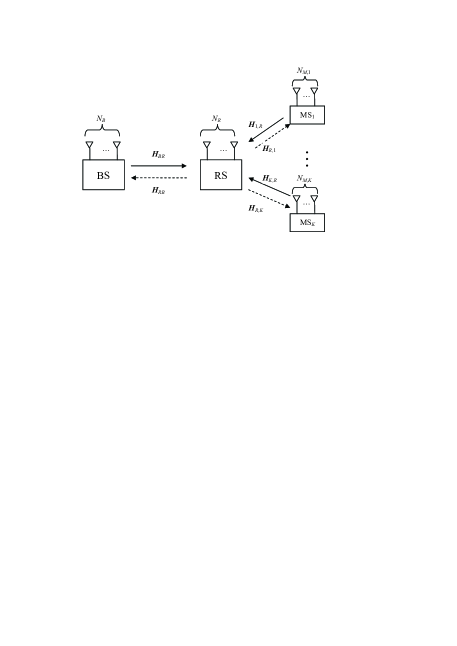
We consider a MIMO cTWRC where a BS communicates with mobile stations (MSs) via a single relay station, as shown in Fig. 1. There is no direct link between the BS and the MSs. The BS, the RS, and the -th MS are equipped with , , and antennas, respectively. We consider quasi-static flat-fading channels where the channel coefficients keep unchanged in the duration of a transmission frame, denoted by . All the nodes are half-duplex and the bidirectional transmission takes place in two phases. For presentation clarity, we consider single-antenna MSs, i.e., , for , and assume . The extension to a general antenna setup will be discussed in Section VI. Each MS exchanges one data stream with the BS, and there are data streams in total. The channel matrix from the BS to the RS is denoted by , and the channel vector from the -th MS to the RS by . and are the corresponding channel matrix/vector for the reverse links. Following the convention (e.g., in [Sun12] and [YangHJ12]), we assume that all the nodes have global channel state information of all links.
The transmission protocol is described as follows. In the first phase, the BS and all the MSs transmit to the RS simultaneously. Let and denote the transmit signal at the BS and the -th MS, respectively. The received signal at the RS is given by
| (1) |
where , , and denotes the additive white Gaussian noise (AWGN) at the RS. It is assumed that each element in is independent and identically distributed (i.i.d.) with zero mean and a variance of . The maximum transmit powers at the BS and the -th MS are and respectively, i.e., , and .
Upon receiving , the transmit signal at the RS is regenerated as , where denotes the RS decoding and re-encoding function. The transmit power of the RS is constrained as , where is the power budget at the relay.
In the second phase, the RS broadcasts to the BS and the MSs. The received signals at the BS and the -th MS are given by
| (2) |
| (3) |
where and are the AWGN at the BS and the -th MS, respectively. With , , and , we have
| (4) |
With the knowledge of the self-message , the BS estimates all the MS messages from the received signal . Meanwhile, for each , the -th MS decodes the intended private message of the BS from with the knowledge of .
For the MIMO cTWRC, let be the transmission rate from the BS to the -th MS, and be the transmission rate from the -th MS to the BS. A rate tuple is said to be achievable if there exist transmit encoding functions, MIMO processing functions, and receive decoding functions at the BS, RS, and MSs such that the decoding error probabilities tend to zero as the codeword length . From the cut-set theorem, two sum-rate outer bounds of the MIMO cTWRC are given by [YangHJ12]
| (5a) | ||||
| (5b) | ||||
where , are the corresponding signaling covariance matrices. These bounds will be used as a benchmark of the system design for the MIMO cTWRC.
III Proposed Two-way Relaying Scheme
In this section, we propose a novel two-phase two-way relaying scheme to approach the sum-rate capacity of the MIMO cTWRC. The key novelty of our scheme, compared to [YangHJ12], is that lattice precoding and random dithering are employed in the first phase to pre-compensate for the inter-stream interference. Building on this theme, encoding and decoding operations at the BS, the RS, and the MSs are carefully designed to enable efficient interference-free PNC decoding at the relay, even with the restriction of non-cooperation among MSs.
III-A Channel Triangularization
To start with, we describe a linear precoding technique to triangularize the channel matrices involved in the two transmission phases, following the approach in [YangHJ12].
Consider the first phase. Let the QR decomposition of be
| (6) |
where is a unitary matrix and is an upper-triangular matrix. Further let the RQ decomposition of be
| (7) |
where is a unitary matrix and is an upper-triangular matrix. By multiplying to the RS received signal , we obtain
| (8) |
where , and .
Let be the coded vector of the BS transmitted to the -th MS. The transmit signal of the BS is linearly precoded as , where is the codeword matrix. The transmit signal of the -th MS is directly generated as , where denotes the coded vector of the -th MS. With such a linear precoding, the RS obtains
| (9) |
where . Correspondingly, the power constraints at the BS and the -th MS can be equivalently written as , and .
The channels from the RS to the BS and MSs can be triangularized in a similar way. Let be an arbitrary permutation matrix. We will see in Section III-E that specifies the DPC re-encoding order at the relay. Let the LQ decomposition of the re-ordered channel matrix be
| (10) |
where is unitary and is lower-triangular.
The transmit signal of the RS is precoded as
| (11) |
where is the DPC codeword matrix to be elaborated in Subsection E. As is unitary, the power constraint of the relay can be equivalently written as .
The permuted received signal at all MSs can be expressed as
| (12) |
where is still an AWGN matrix. Note that there is only one non-zero entry in each row and column of the permutation matrix . For a given , gives a matrix with reordered rows of . This operation doesn’t involve any joint processing of the signals from different MSs. Therefore, the permutation operation is possible, even when the MSs can not cooperate. Based on the signal model in (12), we will show in Section III-F that the achievable rates of the RS-MS link depend on the diagonal of . On the other hand, it follows from (10) that the lower-triangular matrix varies with the choice of the permutation matrix . Hence, the sum-rate performance of the proposed scheme can be improved by searching the optimal permutation matrix .
Now consider the received signal at the BS. Let the QL decomposition of be
| (13) |
where is unitary and is lower-triangular. By multiplying to the received signal in (2), the BS obtains
| (14) |
where . In the above channel triangularization, only unitary transforms are involved, implying that the new signal model in (9), (12) and (14) has the same capacity as the original MIMO cTWRC. Therefore, we henceforth focus on the signaling design for the equivalent MIMO cTWRC given by (9), (12) and (14).
III-B Partitions of Upper-Triangular Matrices and
In the following, we describe the main ideas behind our novel lattice precoding and decoding scheme, based on channel models given in (9), (12) and (14). We first consider the phase-1 channel model in (9). From (9), we can see that and are both upper-triangular matrices. Hence, ISI generally exists in relay decoding. Our objective is to cancel the ISI by combining lattice precoding at the BS and successive interference cancellation at the relay. To this end, we rewrite and as and , with the corresponding signal model (9) re-written as
| (15) |
where is an upper-triangular matrix to be determined shortly. The first term in the right hand side (RHS) of (15), , represents the signal to be decoded at the RS. The second term in the RHS of (15), , denotes the residual inter-stream interference. We need to properly choose such that this interference term can be successively cancelled at the RS with decoding ordered from the -th spatial stream to the first stream. First, to ensure that the second term in (15) only contains inter-stream interference, is required to be strictly upper-triangular, i.e., the diagonal of is chosen the same as that of . Let and be the -th row of and , respectively. In decoding the -th network-coded message , the relay already knows the -th to -th network-coded messages , since the decoding is ordered from the -th spatial stream to the first stream. If the -th inter-stream interference term can be expressed as a linear combination of the -th to -th network-coded messages , then the relay is able to completely remove from the received signal. This is equivalent to say that there exists a strictly upper-triangular matrix :
| (16) |
which satisfies
| (17) |
for arbitrary and . The above condition can be further written as
| (18) |
| (19) |
From (18), can be expressed as
| (20) |
From (19), we have
| (21) |
Substituting (21) into (20), we further obtain
| (22) |
With such choices of and , the relay is then able to remove the inter-stream interference successively with decoding ordered from the -th spatial stream to the first stream .
To see it, let and be the -th row of and , respectively. Then, from (15), the -th subchannel can be expressed as
| (23) |
From (16) and (17), the interference term can be expressed as
| (24) |
which implies that the interference term is a linear combination of the signals . Note that the decoding is ordered from the -th stream to the first stream. When decoding the -th spatial stream , are already decoded and are known to the relay. As a result, the residue ISI can be completely removed from the received signal :
| (25) |
After successive interference cancellation, the -th subchannel scaled by the factor , can be expressed as
| (26) |
where
| (27a) | |||
| (27b) | |||
| (27c) | |||
Note that the decoded signal of the -th stream is . Here, in (27b) is a weighted sum of the last rows of . Let the encoding order of the BS be also from the -th spatial stream to the first stream. Then, when encoding the -th spatial stream at the BS, is known to BS; thus it can be pre-cancelled using lattice precoding at the BS, as will be elaborated in the sequel.
III-C Phase 1: Encoding at the BS and MSs
In the following, we describe the encoding and decoding operations involved in the proposed scheme. We start with the encoding operations at the BS and MSs.
Let be the message set for the data stream at the -th MS, and be the corresponding message. The -dimensional coded vector for the spatial data stream at the -th MS is denoted as , where is the encoding function to be specified in the following. Similarly, the message of the -th spatial stream transmitted to the -th MS at the BS is denoted by , where is the message set. The corresponding -dimensional encoded vector is denoted by .
Nested lattice coding is applied to each message pair . An -dimensional lattice is a subgroup of under normal vector addition. A lattice is nested in the lattice if . The main idea of nested lattice codes is to use the coarse lattice as a shaping region and the lattice points from the fine lattice within the Voronoi region of the coarse lattice as the codewords. The details of nested lattice codes can be found in [Zam02, Erez04, Erez05, Nam10].
The encoding functions and are described as follows. The encoding of the BS follows the order from the -th stream to the first stream sequentially. Without loss of generality, we assume . For the -th subchannel in (26), we construct a nested lattice chain , and satisfying . Here, and are simultaneously Rogers-good and Poltyrev-good while is Poltyrev-good [Nam10]. Let denote the codeword mapped from the message , , where is the nested lattice code defined by and . The coding rate of the nested lattice code can approach any as [Nam10], i.e.
| (28) |
where is the volume of the Voronoi region of a lattice , and as .
For the -th subchannel in (26), and are chosen to meet
| (29) |
where denotes the average power of the -th spatial stream at the BS. Then, the relation between and can be written as [Nam10]
| (30) |
The encoding at the BS is as follows. Let be a random dithering vector that is uniformly distributed over the Voronoi region of , 111It is always assumed that the dithering signals, such as , are globally known to all the nodes in the network.. With random dithering, the -th transmit signal at the BS is constructed as
| (31) |
where the inter-stream interference is a-priori known when encoding the -th stream at the BS (cf. (27b)).
The signal at the -th MS is encoded as
| (32) |
where is a random dithering vector uniformly distributed over the Voronoi region of .
It is worth mentioning that the authors in [YangHJ12] presumed that random dithering cannot be used in the first phase of the MIMO cTWRC due to the non-cooperation among MSs. Interestingly, we will show that through a careful precoder design, random dithering can be in fact employed to improve performance.
III-D Relay’s Operation: Lattice Decoding
We now consider the operations at the relay. The relay’s decoding order is from the -th stream to the first stream. For the -th subchannel in (26), the relay intends to decode the combinations . Recall that in (23) is a weighted sum of the network-coded signals already decoded; hence it can be cancelled from the received signal before Lattice decoding. Together with the knowledge of the dithering vectors and , the relay constructs
| (33a) | ||||
| (33b) | ||||
| (33c) | ||||
where , and . From (31), we see that is a lattice point in . Similarly, is a lattice point in . Hence, is decodable using lattice decoding with a vanishing error probability, provided that [Yuan13]
| (34) |
From (30), we also obtain
| (35) |
Once the lattice point is decoded (with a vanishing error probability as ), the relay can reconstruct , which is used as the known signal to cancel the residual inter-stream interference in subsequent decoding; see (23) and the discussions therein.
III-E Relay’s Operation: Re-encoding
After lattice decoding, the relay calculates
| (36) |
for . Then, one-side DPC encoding is applied to , with an order , so that each MS receives an interference-free signal. Note that the decoding order is specified by as , and . From (12), the received signal at the -th MS can be expressed as
| (37) |
where , denotes the -th row of , and denotes the -th DPC encoded signal. The interference can be pre-cancelled at the RS using dirty paper precoding as
where is a random dither vector that is known by the BS and the MSs, and is the minimum mean square error coefficient for decoding at the MS [Erez04], with being the transmit power of the -th stream of the RS satisfying . The DPC encoded signal is then linearly precoded as (11) and broadcast to the BS and MSs in the second phase.
III-F Phase 2: MS Decoding
The decoding operation at each MS is as follows: For , the -th MS first decode from the received signal ; then it recovers from (i.e., the decoded ) with the help of the knowledge of the self-message and the dither signal . For the first step, it has been shown in [YangHJ12] that the probability vanishes as provided that
| (38) |
Here we focus on the second step, i.e., to recover from . Note that in (36) can be written as
| (39) |
As and are known, the -th MS obtains as
| (40) |
where the second equality follows from
as , and the last equality holds provided .
III-G Phase 2: BS Decoding
The BS first decodes , from the received signal in (14). Note that inter-stream interference still exists at the BS since DPC encoding is only applied to the RS-MS link. However, if the decoding order at the BS is the same as the encoding order at the RS, it was shown in [YangHJ12] that this interference can be successively cancelled at the BS since is lower-triangular. The corresponding probability of vanishes as , provided that
| (41) |
With the knowledge of the self-message , the BS then recovers from by calculating
| (42) |
III-H Achievable Rates of the Overall Scheme
Combining the discussions in Subsections , we have the following theorem for the proposed two-way relaying scheme.
IV Analysis of the Sum-Rate Performance
In this section, we analyze the sum-rate performance of the proposed two-way relaying scheme in the high SNR regime. We first consider the cut-set bound in (5). It is known that, in the high SNR regime, equal power allocation at the BS and the RS is optimal, i.e., , and . Also, as the MSs can not cooperate, the optimal is given by . Then the sum-rate of cut-set bound at high SNR can be written as
where denotes the square of the -th singular value of , , and means as .
We now consider the proposed two-way relaying scheme. From (44), the achievable sum-rate of the proposed scheme is given by
| (45) |
It is difficult to derive a closed-form expression for the optimal power allocation, even in the high SNR regime. In the following, we assume equal power allocation, i.e., , which in general gives a lower-bound of achievable sum-rate. We next show that the proposed scheme with equal power allocation can asymptotically achieve the cut-set bound (IV) under certain conditions.
To start with, we consider the situation that the transmission rate of the BS-to-MS link is bottle-necked by the BS-RS link. For the cut-set bound (IV), it is not difficult to see that the achievable sum-rate of the BS-RS link is no greater than the relayed RS-MS link if the transmit power of the BS satisfies
| (46) |
where . On the other hand, for the proposed scheme with equal power allocation, the transmission rate of the -th spatial stream from the BS to the RS is less than or equal to that from the RS to the -th MS if
| (47) |
where . We will show that if both (46) and (47) hold for all the spatial streams, i.e., , then the proposed scheme achieves the sum-rate cut-set bound of the BS-to-MS link in the high SNR regime. Similarly, the proposed scheme asymptotically achieves the sum-rate capacity if the data transmission of the BS-to-MS link is bottle-necked by the RS-MS link. Furthermore, it can be shown that the cut-set bound of the MS-to-BS link can be achieved in the high SNR regime if the data transmission from the MSs to the BS is bottle-necked by either the MS-RS link or the RS-BS link. Following these lines, we define the conditions C1-C4 as follows:
C1: ;
C2: ;
C3: ;
C4: ,
where , and
. Then we can establish that: