Giant field enhancement by funneling effect into sub-wavelength slit-box resonators
Abstract
Inspired by the acoustic Helmholtz resonator, we propose a slit-box electromagnetic nanoantenna able to concentrate the energy of an incident beam into surfaces a thousand times smaller than with a classical lens. This design gives birth to giant field intensity enhancement in hot volume, throughout the slit. It reaches in the visible up to in the THz range even with focused beams thanks to an omnidirectional reception. These properties could target applications requiring extreme light concentration, such as SEIRA, non-linear optics and biophotonics.
pacs:
Optical nanoantennas are of great importance for harvesting light from the free space to deep-subwavelength volume and to reach a strong electric field enhancement Lerosey et al. (2007); Grbic et al. (2008); Zhang et al. (2008); Novotny and van Hulst (2011); Biagioni et al. (2012); Barnes et al. (2003); Greffet (2005); Schuller et al. (2010). They have a wide range of applications including surface enhanced Raman scattering (SERS) Siegfried et al. (2013), photovoltaics and photodetection Knight et al. (2011), non-linear optics Kauranen and Zayats (2012), bio-sensing Liu et al. (2011), surface enhancement infrared absorption (SEIRA) Dregely et al. (2013); Bochterle et al. (2012); Adato et al. (2009), and thermal emission Schuller et al. (2009). Field intensity enhancement up to was observed using subwavelength particles Mühlschlegel et al. (2005) and an enhancement up to is expected inside self-similar chains Li et al. (2003). Inspired by radiofrequency designs, various nanoantennas have been engineered to improve the field enhancement in larger volumes, such as bow-tie Schuck et al. (2005); Kim et al. (2008), quarter-wave or Yagi-Uda Novotny (2007); Kosako et al. (2010); Dregely et al. (2011) antennas. However, the antennas previously proposed either concentrate the electric field only in hot spots, or are plagued by their directivity which prevents them to be used with focused beam. The key issue to further enhance the electromagnetic field is thus to design an antenna having a large angular acceptance as well as a wide cross-section. Here, we present a slit-box resonator inspired by the acoustic Helmholtz resonator von Helmholtz (1896), which is able to omnidirectionally funnel all the light through its aperture regardless of its width, leading to million fold electric field intensity enhancement in a hot volume. This design, allows to tune independently the slit (width: , height: ) and the cavity geometries for a given resonance wavelength and we demonstrate that it leads to a giant enhancement factor driven by the ratio . This enhancement factor only depends slightly on the angle of incidence which permits to use this antenna at the focal spot of a classical lens to further strongly enhance the electric field intensity. This giant field intensity enhancement opens great perspectives of application for devices based on SEIRA or nonlinear optics which used focused beam.
The funneling by magneto-electric interference was shown to efficiently collect light into 2D sub-wavelength slits with a near- cross section and a large angular acceptance Pardo et al. (2011); Bouchon et al. (2011); Subramania et al. (2011); Chevalier et al. (2012). In the following, the funneling effect is applied to a single Helmholtz-like nanoantenna at the focal point of a focused beam. Our electromagnetic structure is made of a metallic material and is long enough along the y direction to be considered as infinite. It consists in a box (width , height ) and a slit (width , height ) as shown in Fig. 1(a). A beam is focused on one of these structures where almost all the incident energy is funneled. Exact Maxwell computations Bouchon et al. (2010) of this slit-box resonator are performed by considering that the metallic walls are made of gold. Its dielectric function is computed from the Drude model which matches well the experimental data in the infrared domain for and Palik and Ghosh (1985). In the following we consider a box of width and of height , and a slit of width and of height qua that is firstly studied at .
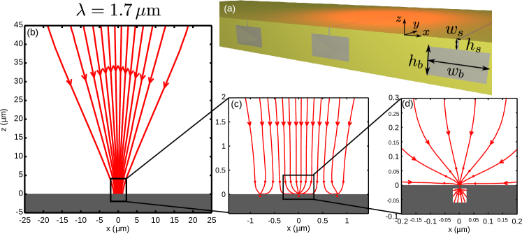
The behavior of the structure has been simulated by focusing a beam onto a slit-box structure. Technically the structure is periodized with a period slightly smaller than the wavelength (see supplementary materials). The streamlines of the Poynting vector plotted at a large scale in Fig. 1(b) show that the incident energy is focused into a beam limited by diffraction (see Fig. 1(c)) where 90% of the energy is concentrated in a -wide spot (here the wavelength is ). Next, in the near field (, see Fig. 1(d)), all the focused energy is funneled towards the opening of the resonators where it is absorbed on the metallic sidewalls. In fact, given the size of the focal spot, 60% of the total energy is absorbed by the central resonator while the remaining energy is equally absorbed by the two surrounding resonators. Since the incoming energy goes through the slit of the resonator, the electric field intensity is strongly enhanced in the whole slit volume.
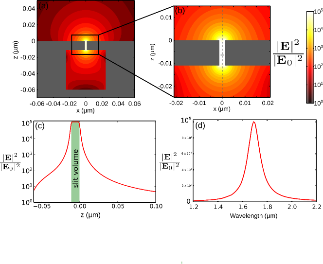
The distribution of the electric field intensity () normalized by the incident field intensity () in the central structure is presented in Figs. 2(a)-2(b) at different zoom levels and shows that a field intensity enhancement of is reached with this structure. In Fig. 2(c), it is shown that this enhancement is confined to the slit volume: the field intensity enhancement stays constant along the height of the slit, but outside its volume the electric field intensity quickly drops by losing 4 orders of magnitude over about . Noteworthily, this profile of the electric field departs from the behaviour of a Fabry-Perot slit, and it adds to the fact that the slit-box resonator does not exhibit harmonics features (see Fig. S1 in supplemental materials.)The quality factor is for a resonance wavelength of as shown in Fig. 2(d). In the supplementary materials, we show that the slit-box structure is fairly well described by a LC resonator model (the capacitor being the slit, and the inductance being the box that acts as a magnetic energy accumulator), giving an analytic formula for the resonance wavelength: where is the refractive index of the dielectric material filling the slit. It must be emphasized that, as expected from the inductive nature of the box, its dielectric filling plays no role on the resonance wavelength.
For an incident wave polarized with the electric field perpendicular to the slits, the maximum field intensity enhancement in the slit at the resonance can be expressed as:
| (1) |
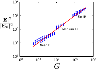
where is the quality factor of the resonance, is the wavelength. This formula stems from the expression of the stored energy and the dissipated energy inside the resonators (see supplementary materials). It stands for a plane wave normally incident onto a perfectly impedance-matched structure, exhibiting total absorption (i.e. neither scattered nor reflected fields). In a more general situation, where the energy absorption efficiency is different from , or when the period is different from , the field intensity enhancement writes . In figure 3 the enhancement factor has been calculated for variously shaped structures () exhibiting resonances from the near infrared to the far infrared and is plotted as a function of . This figure shows the good agreement between this analytic model and the values obtained through numerical simulations in the different domains of frequencies.
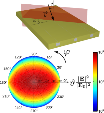
The angular dependence of the enhancement is studied in Fig. 4. The general configuration of conical incidence is described in Fig. 4(a), the light is impinging on the antenna with an angle in the plane defined by the azimuthal angle and is polarized so that the magnetic field is in the plane. The enhancement G as a function of both angles is plotted in Fig. 4(b). It remains above for angle of incidence below which demonstrates the omnidirectional behaviour of the resonator. Due to its high angular tolerance, the enhancement G would only be slightly reduced when the structure is placed at the focal spot of a lens. In this case, the electric field intensity would be similar to the one obtained if, beyond the limits of diffractive optics, a beam of given power was focused in a spot of area instead of . Noteworthily, this intensity is uniformly obtained in a “hot volume” of height and area .
Very strong field intensity enhancements can be reached not only in the infrared range, but in the whole spectrum from visible to THz domain. At higher wavelengths, losses in the metal are weaker than in the near IR, so the quality factor of the resonance is greater. Therefore, higher field intensity enhancements will be reached at longer wavelengths. As shown in the supplementary materials, such structures allow higher enhancement factors for the intensity of the electric field than in the literature: vs. Mühlschlegel et al. (2005); Dregely et al. (2013); Adato et al. (2009); Schuller et al. (2010) in the near IR or visible, vs. in the far IR Feuillet-Palma et al. (2013), and vs. in the THz domain Seo et al. (2009).
The slit-box structure allows to funnel nearly all the incident energy through the arbitrarily narrow aperture of the slit leading to giant enhancement of the electric field in the whole slit volume. These appealing properties are very promising for light matter interactions such as in photodetection, SERS, SEIRA and non-linear optics.
Acknowledgements.
We are thankful to J.-J. Greffet for precious discussions concerning this manuscript. We acknowledge financial support from the ONERA through the SONS project.References
- Lerosey et al. (2007) G. Lerosey, J. de Rosny, A. Tourin, and M. Fink, Science 315, 1120 (2007).
- Grbic et al. (2008) A. Grbic, L. Jiang, and R. Merlin, Science 320, 511 (2008).
- Zhang et al. (2008) Z. Zhang, R. Peng, Z. Wang, F. Gao, X. Huang, W. Sun, Q. Wang, and M. Wang, Applied Physics Letters 93, 171110 (2008).
- Novotny and van Hulst (2011) L. Novotny and N. van Hulst, Nature Photonics 5, 83 (2011).
- Biagioni et al. (2012) P. Biagioni, J.-S. Huang, and B. Hecht, Reports on Progress in Physics 75, 024402 (2012).
- Barnes et al. (2003) W. Barnes, A. Dereux, T. Ebbesen, et al., Nature 424, 824 (2003).
- Greffet (2005) J.-J. Greffet, Science 308, 1561 (2005).
- Schuller et al. (2010) J. Schuller, E. Barnard, W. Cai, Y. Jun, J. White, and M. Brongersma, Nature Materials 9, 193 (2010).
- Siegfried et al. (2013) T. Siegfried, Y. Ekinci, O. J. F. Martin, and H. Sigg, Nano Letters 13, 5449 (2013), http://pubs.acs.org/doi/pdf/10.1021/nl403030g .
- Knight et al. (2011) M. Knight, H. Sobhani, P. Nordlander, and N. Halas, Science 332, 702 (2011).
- Kauranen and Zayats (2012) M. Kauranen and A. V. Zayats, Nature Photonics 6, 737 (2012).
- Liu et al. (2011) N. Liu, M. L. Tang, M. Hentschel, H. Giessen, and A. P. Alivisatos, Nature materials 10, 631 (2011).
- Dregely et al. (2013) D. Dregely, F. Neubrech, H. Duan, R. Vogelgesang, and H. Giessen, Nature communications 4 (2013).
- Bochterle et al. (2012) J. Bochterle, F. Neubrech, T. Nagao, and A. Pucci, ACS nano 6, 10917 (2012).
- Adato et al. (2009) R. Adato, A. A. Yanik, J. J. Amsden, D. L. Kaplan, F. G. Omenetto, M. K. Hong, S. Erramilli, and H. Altug, Proceedings of the National Academy of Sciences 106, 19227 (2009).
- Schuller et al. (2009) J. A. Schuller, T. Taubner, and M. L. Brongersma, Nature Photonics 3, 658 (2009).
- Mühlschlegel et al. (2005) P. Mühlschlegel, H. Eisler, O. Martin, B. Hecht, and D. Pohl, Science 308, 1607 (2005).
- Li et al. (2003) K. Li, M. I. Stockman, and D. J. Bergman, Physical Review Letters 91, 227402 (2003).
- Schuck et al. (2005) P.J. Schuck, D.P. Fromm, A. Sundaramurthy, G.S. Kino, and W.E. Moerner, Physical Review Letters 94, 017402 (2005).
- Kim et al. (2008) S. Kim, J. Jin, Y.-J. Kim, I.-Y. Park, Y. Kim, and S.-W. Kim, Nature 453, 757 (2008).
- Novotny (2007) L. Novotny, Phys. Rev. Lett. 98, 266802 (2007).
- Kosako et al. (2010) T. Kosako, Y. Kadoya, and H. F. Hofmann, Nature Photonics 4, 312 (2010).
- Dregely et al. (2011) D. Dregely, R. Taubert, J. Dorfmüller, R. Vogelgesang, K. Kern, and H. Giessen, Nature communications 2, 267 (2011).
- von Helmholtz (1896) H. von Helmholtz, Theorie der Luftschwingungen in Röhren mit offenen Enden, 80 (W. Engelmann, 1896).
- Pardo et al. (2011) F. Pardo, P. Bouchon, R. Haidar, and J.L. Pelouard, Physical Review Letters 107, 093902 (2011).
- Bouchon et al. (2011) P. Bouchon, F. Pardo, B. Portier, L. Ferlazzo, P. Ghenuche, G. Dagher, C. Dupuis, N. Bardou, R. Haïdar, and J. Pelouard, Applied Physics Letters 98, 191109 (2011).
- Subramania et al. (2011) G. Subramania, S. Foteinopoulou, and I. Brener, Phys. Rev. Lett. 107, 163902 (2011).
- Chevalier et al. (2012) P. Chevalier, P. Bouchon, R. Haïdar, and F. Pardo, Journal of Nanophotonics 6, 063534 (2012).
- Bouchon et al. (2010) P. Bouchon, F. Pardo, R. Haïdar, and J. Pelouard, Journal of the Optical Society of America A 27, 696 (2010).
- Palik and Ghosh (1985) E. Palik and G. Ghosh, Handbook of optical constants of solids (Academic press, 1985).
- (31) Since we do not take into account the non localities and quantum effects, this model for the strong field intensity enhancement is valid for slits of widths greater than Esteban et al. (2012).
- Feuillet-Palma et al. (2013) C. Feuillet-Palma, Y. Todorov, A. Vasanelli, and C. Sirtori, Scientific Reports 3 (2013).
- Seo et al. (2009) M. Seo, H. Park, S. Koo, D. Park, J. Kang, O. Suwal, S. Choi, P. Planken, G. Park, N. Park, et al., Nature Photonics 3, 152 (2009).
- Esteban et al. (2012) R. Esteban, A. G. Borisov, P. Nordlander, and J. Aizpurua, Nature Communications 3, 825 (2012).