A 31 split-pair pulsed magnet for single crystal x-ray diffraction at low temperature
Abstract
We have developed a pulsed magnet system with panoramic access for synchrotron x-ray diffraction in magnetic fields up to 31 and at low temperature down to 1.5. The apparatus consists of a split-pair magnet, a liquid nitrogen bath to cool the pulsed coil, and a helium cryostat allowing sample temperatures from 1.5 up to 250. Using a 1.15 mobile generator, magnetic field pulses of 60 length were generated in the magnet, with a rise time of 16.5 and a repetition rate of 2 pulses/hour at 31. The setup was validated for single crystal diffraction on the ESRF beamline ID06.
pacs:
Valid PACS appear hereI Introduction
Of all x-ray techniques, single crystal diffraction with a monochromatic beam offers by far the highest resolution, the strongest absolute signal, and the best signal to noise ratio. It is therefore the method of choice for the examination of small crystallographic changes (such as magneto-elastic effects), and for weak signals (such as magnetic scattering or scattering of orbital order). Unlike x-ray diffraction techniques such as white beam Laue diffraction or powder diffraction, however, this technique requires precise alignment of the sample and is therefore sensitive to vibrations that might be introduced by electromagnetic forces induced by the field pulse. It requires optical access over a wide angular range to enable measurements at high scattering angles.
In many cases the magnetic field induced effects are anisotropic and require the application of the field along a specific crystallographic axis. The challenge of combining x-ray single crystal diffraction and pulsed high magnetic fields was taken up by several groups over the world during the last ten years Matsuda et al. (2004); Narumi et al. (2006a, b); Matsuda et al. (2006); Islam et al. (2009, 2012).
With this specific aim, the simplest way to obtain a coil with large optical access in the mid plane perpendicular to the magnetic field is to use two coils, series connected and axially aligned, with a gap between them. In this arrangement, commonly called split-pair magnet, the vertical axial bore is used to insert the sample cryostat, and the horizontal mid plane gap is used for x-ray access. Over the years, several pulsed magnets of split-pair type Matsuda et al. (2004); Narumi et al. (2006a, b); Matsuda et al. (2006); Islam et al. (2009) have been developed to meet the requirements for combining x-ray diffraction with high pulsed magnetic field. However, only very few publications Islam et al. (2012) have shown the difficulties to associate both techniques and the efforts required to reduce the pulse induced vibrations, and to make x-ray single crystal diffraction compatible with pulsed magnetic field.
Here, a new pulsed field set-up, including a split-pair magnet and sample cryostat, both specifically designed and optimized for single crystal measurements on a synchrotron x-ray beamline, is presented. Particular efforts have been carried out to quantify the vibrations. Several technical changes have been made on the pulsed magnet and cryogenic assembly by the LNCMI-Toulouse (LNCMI-T) and on the beamline at the ESRF-Grenoble, to minimize the vibrations and their propagation.
This device offers the possibility to invert the magnetic field polarization and to change the sample temperature over a wide range while optimally cooling the coil. After a detailed description of the different parts of the system we present its main features as regards of field, temperature and angular resolution, illustrated by first results obtained on a Fe1.1Te single crystal.
II Pulsed field device and cryogenics
II.1 The split-pair magnet: design and construction
The split-coil magnet described here was designed and built at the LNCMI-T. It is composed of two coils consisting of 36 layers of 13 turns. The wire choice was the result of a trade-off between low resistivity to reduce coil heating and high ultimate tensile stress (UTS) to resist to magnetic pressure. A copper conductor, internally reinforced by niobium titanium filaments and insulated with kapton, was used. Its main features are reported in Table 1.
| Cross section | 5.77 mm2 |
|---|---|
| Thickness width | 2 mm 3.15 mm |
| Ultimate tensile stress | UTS 1 GPa |
| Resistivity | 0.35 .cm |
| 2.9 .cm |
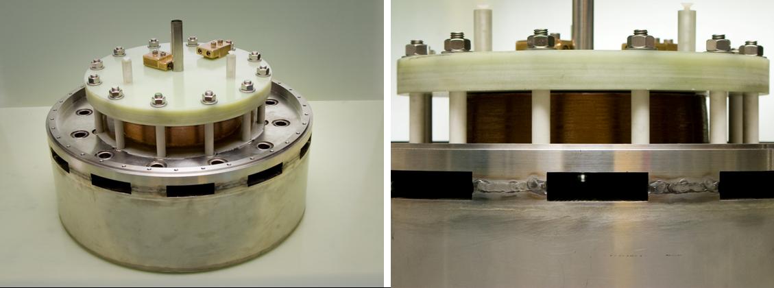
The usable space for sample and cryogenics is determined by the magnet bore diameter and the gap between the two coils. Stainless steel spacers were inserted between both magnets to withstand the pressure ( 200 MPa) resulting from attraction induced by Lorentz forces on the two coils. These spacers were designed with open sectors for x-ray beam access alternating with closed sectors (see Fig. 1). A thin layer of Teflon and 2 of glass fiber epoxy composite (FR4/G10) were added between the coils and the spacers to increase electrical insulation and internal mechanical reinforcement.
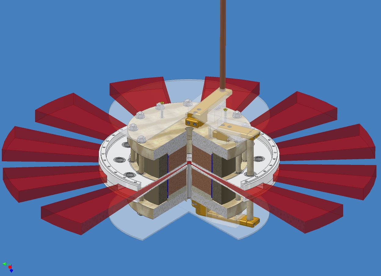
With an inner diameter of 22, an outer diameter of 200, a height of 50 per coil and a gap of 20, the total height of the split-pair magnet is 120 and the resulting inductance . At the center of the magnet, the vertical length available for the sample is of and the vertical angular opening of each open sectors is of (see Fig. 2).
This split-pair magnet was designed to generate a maximum field of 30 at the sample position. This design goal was achieved as the final coil reached a field of 31 in user operation.
II.2 Cryogenic environment description
The cryogenic system consists of a liquid nitrogen (LN2) bath cryostat that houses the coils, and a separate liquid 4He cryostat for the sample.
II.2.1 LN2 bath cryostat
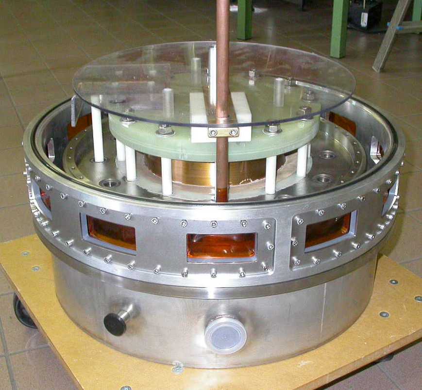
The split-pair magnet was integrated into a custom designed nitrogen cryostat equipped with twelve x-ray transparent, vacuum tight Kapton windows (foils of 120 thickness). The latter are distributed around the Dewar (Fig. 3), matching the optical access sectors in the spacers between the magnets. The internal vessel of this cryostat is divided in two parts (the lower and upper baths), each containing a coil (Fig. 4). A stepped tube, intended to house the 4He insert, passes through the bore of the split-coil (see Fig. 2 and 4). Connection and continuity between the lower and upper baths are ensured by twelve stainless steel tubes traversing the spacers. This configuration allows the use of a common vacuum for the nitrogen cryostat, the helium insert and the x-ray beam path.
II.2.2 4He insert cryostat
The coil/LN2 cryostat assembly hosts a top loading 4He cryostat allowing measurements in the temperature range 1.5 – 250 K.
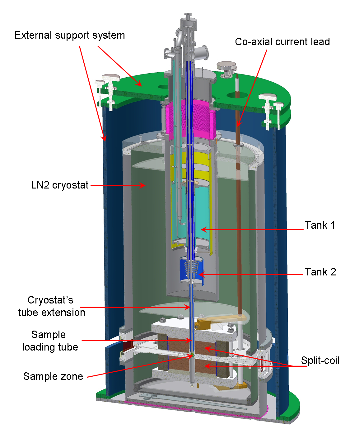
As shown on figures 4 and 5, the 4He cryostat consists of five parts: the main bath (tank 1), a 2.5 heat exchanger, the 1.5 bath (tank 2) with its extension, the sample loading tube system and the sample zone.
The main bath (tank 1) is a 3l liquid helium vessel. It is connected with the 1.5 bath (tank 2, 0.4l) via a tube of 2 inner diameter equipped with a cold valve. When open, the valve allows refilling of tank 2 with liquid 4He from the main bath while, when closed, tank 1 can be refilled with almost no effect on the temperature of tank 2. The latter is extended by a vertical stainless steel tube of 15 outer diameter (the “cryostat’s tube extension”) equipped with a joule heater and a Cernox calibrated thermometer.
The cryostat includes also a 2.5 heat exchanger pumped by an independent pumping line. This exchanger is continuously supplied with liquid helium coming from the tank 1 and includes in its lower part a Joule Thomson (J-T) impedance (capillary of 10 length and 0.15 inner diameter) allowing the expansion of the helium gas and, therefore, the cooling of the vapors in the inner part of the exchanger down to 2.5. In closed cycle mode, the He flow is injected through a long capillary (stainless steel tube of 1.2 length and 1 inner diameter), wound inside the exhaust line of the tank 1, traversing the tank 1 and the exchanger before entering in the upper part of the tank 2. The flow is then distributed via two needle valves in two different lines. The first valve allows to regulate the temperature between 4 and 250 K, the line being wound around the joule heater’s support located in the lower part of the cryostat’s tube extension. The second valve allows to reach temperatures as low as 1.5, this line being extended by a long and thin capillary (1 length and 0.5 inner diameter) twisted inside the cryostat’s tube extension and ending with a final impedance (capillary of 5 length and 0.15 inner diameter).
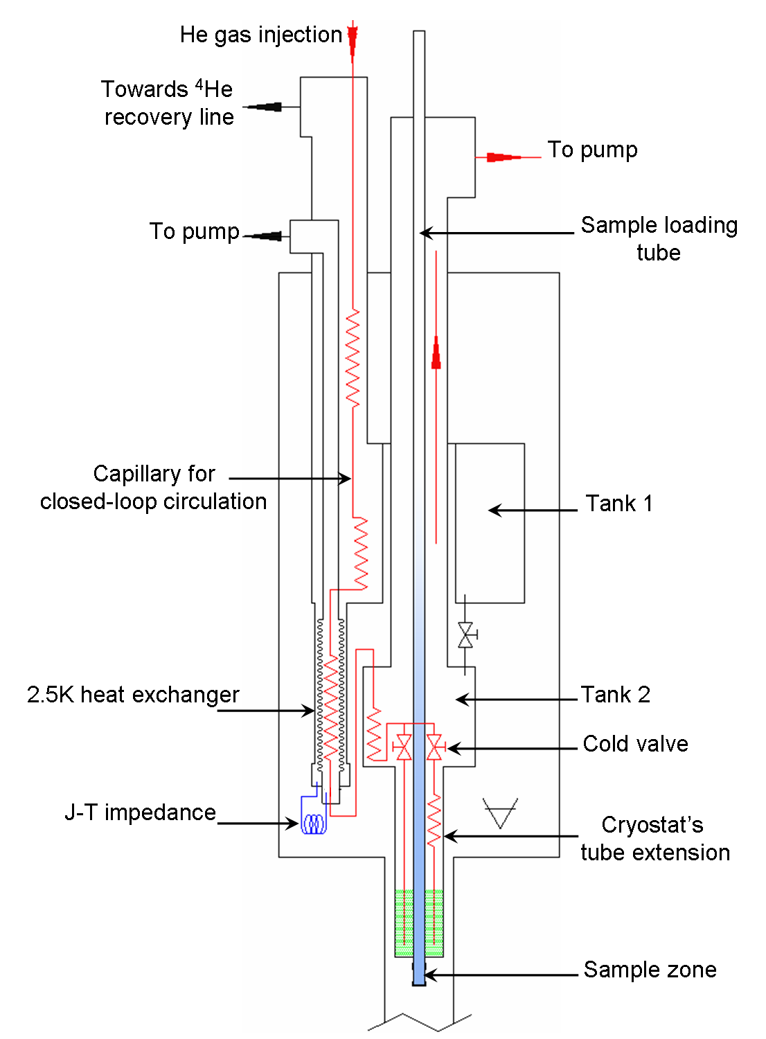
The sample loading system is a tube of 7.6 inner diameter and 0.2 thick going through the whole length of the insert (from the top at room temperature down to the vicinity of the magnetic field center). The sample zone is located at the center of the magnetic field. It consists of a capsule of 800 thick Torlon, a polymer fairly transparent to x-ray, glued (Stycast 2850 FT) to the bottom end of the sample loading tube. A brass foil tube, radially drilled and thermally anchored to the cryostat tube extension, surrounds the capsule and is covered with several layers of super insulation to screen against the thermal radiation from the Kapton windows at room temperature. The sample zone and the loading tube were designed to be easily evacuated, then loaded with a few cm3 of 4He exchange gas at room temperature and pressure. In operation the external surface of the loading tube is in direct contact with the liquid 4He of the cryostat tube extension while its internal surface is in contact with the exchange gas. The sample is thus cooled down by exchange gas to the bath temperature.
To mechanically decouple the 4He insert from the magnet and LN2 cryostat, and to allow fine adjustment of the 4He cryostat’s tube extension inside the vacuum enclosure, an additional external support system (Fig. 4) was built in order to avoid mechanical and thermal contact.
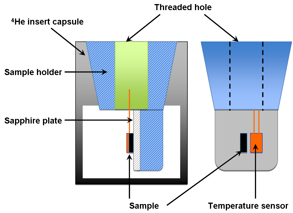
Finally, a sample handling system has been designed specifically to prevent sample motion (rotation and/or translation of sample holder) induced by field pulses. It consists of the sample holder coupled with the capsule located at the bottom of the 4He insert. Both parts are made in Torlon, thus avoiding induced currents in the sample holder. The upper parts of both elements have a conical shape (see Fig. 6) allowing to physically lock the sample holder inside the 4He cryostat after alignment of the sample in Bragg condition. The stability of the sample orientation is thus ensured over time. The sample handling system is complemented with a measurement stick which is equipped with a pick-up coil and a heating resistance. To improve thermal conductivity, a thin sapphire plate (thickness ) covers the part of the sample holder where the sample is glued with GE varnish.
All the cryogenic environment has been custom designed and built at the LNCMI-T.
II.3 Generator
The split-pair magnet was used with a 24, 1.15 transportable pulsed field generator developed by the LNCMI-T. This generator consists of two identical storage units and one control unit. Each storage unit contains eight high energy density capacitors of 250 each, resulting in a total capacitance of 4, two crowbar resistors () and two inductive current limiters (). The control unit houses the charger, thyristor stack, dump resistors, the current and voltage monitors. This unit is also equipped with high-voltage, high-current pneumatically driven commutators to give the possibility to work with two polarities. Commutation and charging take only a few minutes and is controlled completely by a computer integrated in the central control unit. The energy of the capacitor bank is released into the coil through an optically triggered thyristor switch. The bank is protected from failure in case of a short in one capacitor. To avoid an electrical dump of all the other capacitors into the defective one, they are all equipped with industrial HV-fuses.
The three subunits are mounted in individual steel frames so that they can be transported using a fork lift or an overhead crane. Each storage module weighs approximately 2000 and has dimensions () . The control unit is slightly smaller () and weighs only 800. The connections between the three subunits are made on external patch panels and do not require opening of the units’ enclosures. The generator can thus be safely installed by users with minimal training. For our synchrotron experiments, the generator, located outside the experimental hutch, was linked to the personal safety system (PSS) of the radiation hutch such that it could be charged only after the hutch had been searched and interlocked.
III Commissioning
III.1 Coil operation
The coil parameters as measured during coil testing were: a resistance value and 1650 at 77 and 300, respectively, an inductance and a field factor of 169.2.
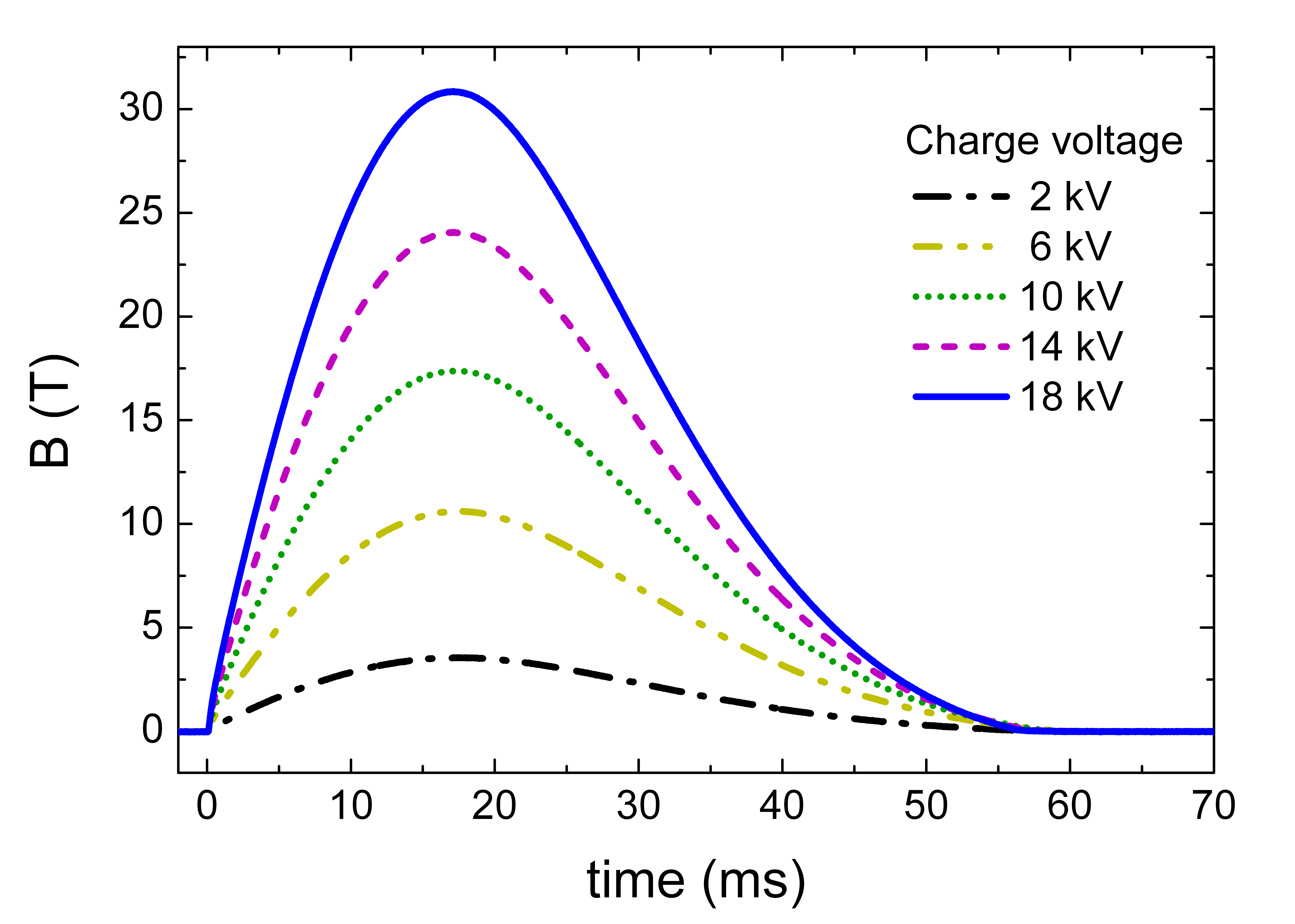
Maximum magnetic field of 31 was achieved at the center of the split-pair magnet for a charging voltage of . The pulse duration was of 60 with a rise time of 16.5, as shown on figure 7. With more than 4.5 above 98% of the maximum field value, this pulse is relatively long compared to the other pulsed field devices developed for x-ray and neutron scattering experiments Matsuda et al. (2004); Narumi et al. (2006a, b); Matsuda et al. (2006); van der Linden et al. (2008); Yoshii et al. (2009); Islam et al. (2009, 2012). In addition, the magnetic field produced at the center of the magnet is fully homogeneous over typical size of single crystals probed by x-ray (i.e., from hundreds of micrometers to one or two millimeters) with less than 1% of variation over 3 along the bore of the magnet and less than 0.5% radially (over a radius ). The energy stored into the coil at maximum field value is relatively high () and at the end of the pulse its electrical resistance shows an increase of about equivalent to a coil heating of 40. Around half an hour is then required between two pulses at 31 to return to the coil operating temperature of 90.
III.2 Low temperature measurements
The cryogenic performances have been tested successively in open cycle and closed cycle mode. In open cycle mode tank 2 is filled with liquid 4He at 4.2 by opening the cold valve between tanks 1 and 2. The cold valve is then closed, and by pumping on tank 2 a sample temperature of 1.5 can be obtained within a few minutes. This temperature can be maintained for around three hours before tank 2 has to be refilled.
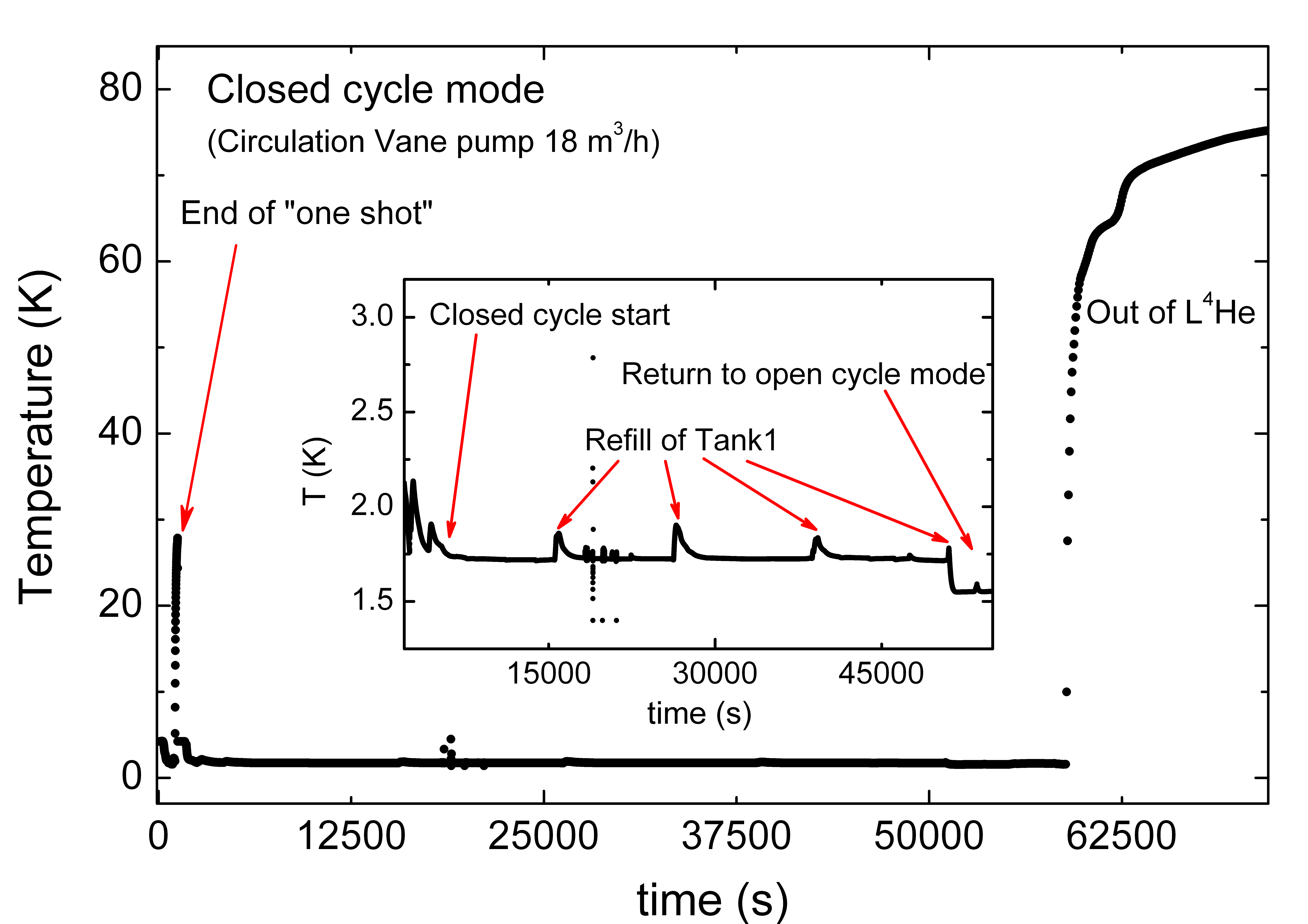
In closed cycle mode, a continuous flow of cold He gas arrives close to the sample zone through the capillary that traverses the tank 1, the 2.5 heat exchanger, the tank 2, the cold needle valve and the final capillary, whereas only the bottom part of tank 2 (tube extension) is filled with a few cm3 of liquid 4He. By pumping on tank 2 with a rotary vane pump (Edwards E2M40), a base temperature of 1.5 (1.7 when using a E2M18 pump, as shown on Fig. 8) is reached within less than 20 minutes and can be maintained for more than 13 hours provided that tank 1 is refilled periodically. In experiment conditions, i.e. when the sample is exposed to x-ray, this temperature can be preserved by using absorber foils before the sample in the incident beam path, thus reducing the flux incident on the sample to photons/s. For the Fe1.1Te experiments shown here, at 31, we used two Sn foils of 50 m each. In addition, a fast x-ray shutter (LS200 Laser shutter from NM Laser products, Inc. (San Jose, CA, USA)) is used to expose the sample during very short time (100 ms per magnetic field pulse).
IV High resolution X-ray single crystal diffraction and pulsed magnetic field
Commissioning tests of the split-pair magnet were performed on the undulator beamline ID06 (ESRF, Grenoble, France).
The source device was a cryogenically cooled permanent magnet undulator (CPMU) Chavanne (2007) with 18 period and 6 minimum gap, such that the first harmonic could be tuned from 10.5 to 19.0. A liquid nitrogen cooled Si (111) double crystal monochromator selected photons with a relative band width of . The maximum achievable photon flux was about at 11.
The cryostat and magnet assembly was installed in the experimental hutch 2 (EH2) on a high-load six circle diffractometer identical to that of ID20 Paolasini et al. (2007). The generator was installed in an enclosure outside of the experimental hutch, and connected to the magnet via a coaxial cable. A pneumatically operated switch disconnected the generator from the magnet when the hutch was not interlocked, i.e. when access to the hutch was allowed.
IV.1 Characterization of vibrations and angular stability
The tests were first carried out on silicon single crystals to estimate the vibration amplitude of the complete device. The diffracted intensities were measured with a silicon photodiode mounted on the detector arm of the diffractometer and recorded (along with generator voltage and current, and the voltage on a pick-up coil on the sample stick) during the field pulses on a digital data recorder (HIOKI Memory HiCorder model 8860). Motorized slits upstream of the photodiode detector at 70 from the sample position were used to adjust the longitudinal () resolution. Due to the very narrow rocking curve width of the silicon crystal and the low divergence of the incident x-ray beam this configuration is extremely sensitive to rotations of the sample during the field pulse.
One main source of vibrations identified on the beamline was eddy currents propagating in the aluminium parts of the diffractometer. To increase the distance from the field center to those parts and suppress the repulsive forces generated by induced currents, several aluminium parts such as the goniometer top plate and rotation stages ( and stages) of the diffractometer were removed and replaced by fiber glass spacers (FR4/G10). The remaining aluminium parts were thus located at more than 49 from the center of the magnet. Induced eddy currents and corresponding forces were sufficiently weak to not disturb the measurement anymore.
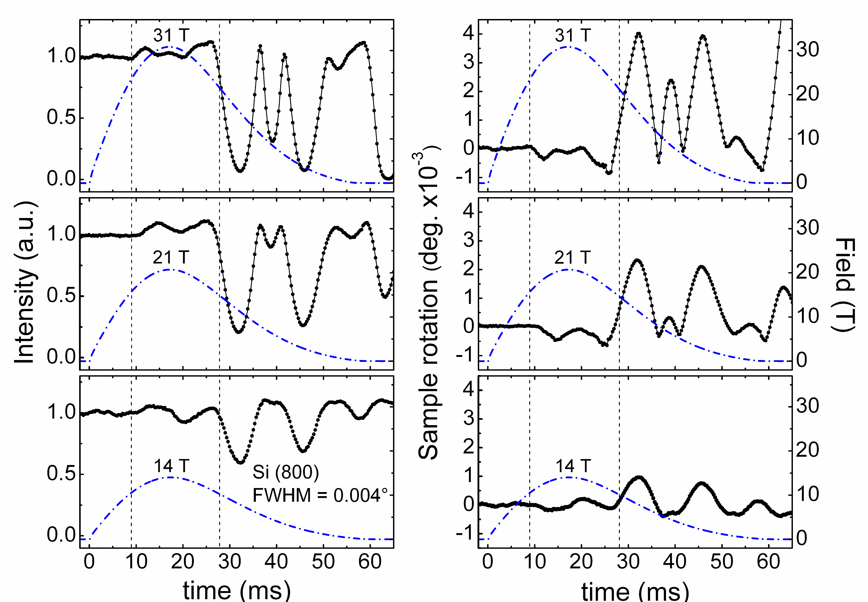
As an example, the evolution of the normalized intensity of a Si (800) Bragg reflection (FWHM()) is shown on figure 9 (left) as a function of time for different amplitudes of field pulses: 14, 21 and 31. The intensity begins to oscillate 9 after the magnetic field pulse was triggered. However, the variation of intensity does not exceed 17% during the first half of the pulse (i.e. up to 28 after the beginning of the pulse). Then, between 28 and 60, the amplitude of the oscillation increases, with the intensity even going through zero for the 31 pulse. The orientation of the sample is nevertheless maintained since the intensity is recovered with no more oscillation 1 after the pulse (not shown).
By measuring the change of intensity at slightly lower or higher sample angles () than the Bragg position, it was possible to ascribe the loss of intensity to sample rotation. The latter was easily calculated as a function of time based on the full width at half maximum of the reflection and pseudo-Voigt like shape of Bragg peaks. The result is displayed on figure 9 (right). These curves show that sample rotation is always lower than during the first half of the pulse and does not exceed at maximum field, well below the mosaicity of most single crystal samples of interest for high-field studies (e.g. for typical intermetallic compounds). In the second half of the pulse, the rotation is as high as for the shot at maximum field value.
This means that our experimental setup is not suitable for studying intensity changes over the entire field pulse for very high quality samples with mosaicity below . One should note, however, that the usable pulse length is at least five times higher than the one provided by the other pulsed field devices dedicated to x-ray single crystal diffraction experiments Narumi et al. (2006a, b); Islam et al. (2009, 2012). This is of advantage for studying metallic samples and hysteresis effects. Furthermore, the longer rise time induces less sample heating due to induced currents.
Other efforts have been carried out to further suppress or reduce vibrations, but they yielded no significant improvement, e.g. decoupling the coil cryostat from the diffractometer and sample cryostat by means of viscoelastic absorbers, and increasing the stiffness of the diffractometer by means of external reinforcements.
While simple, cheap and easy to use, a point detector such as a photodiode requires at least one magnetic field pulse per scattering angle, and is thus not exactly very efficient for studies of magnetic field induced crystallographic phase transitions. On the other hand, a fast 2D detector can follow the evolution of Bragg peaks during magnetic field pulses Narumi et al. (2006a, b), i.e. it allows the observations of intensity changes at several scattering angles simultaneously. In our first experiments a MAXIPIX detector Ponchut et al. (2011) was used. This is a fast readout, active pixel detector based on the Medipix2 Llopart et al. (2002) and Timepix Llopart et al. (2007) readout chips developed by CERN and the Medipix2 collaboration. The system achieves up to 1.4 frame rate with 290 minimum readout dead time and has a pixel size of . We used the single chip ( pixels) detection geometry. In this geometry, with the detector mounted on the detector arm (-arm) of the diffractometer at a distance of 53 from the sample, the accessible angular width in both the vertical and horizontal direction is around ∘, and the angular resolution corresponding to the pixel size is approximately 0.006∘ in 2. The resolution could be increased by increasing the distance to the sample, e.g. to 0.0037∘ at 85 from the sample. This, however, reduces the angular field of view to ∘ in both the vertical and horizontal direction.
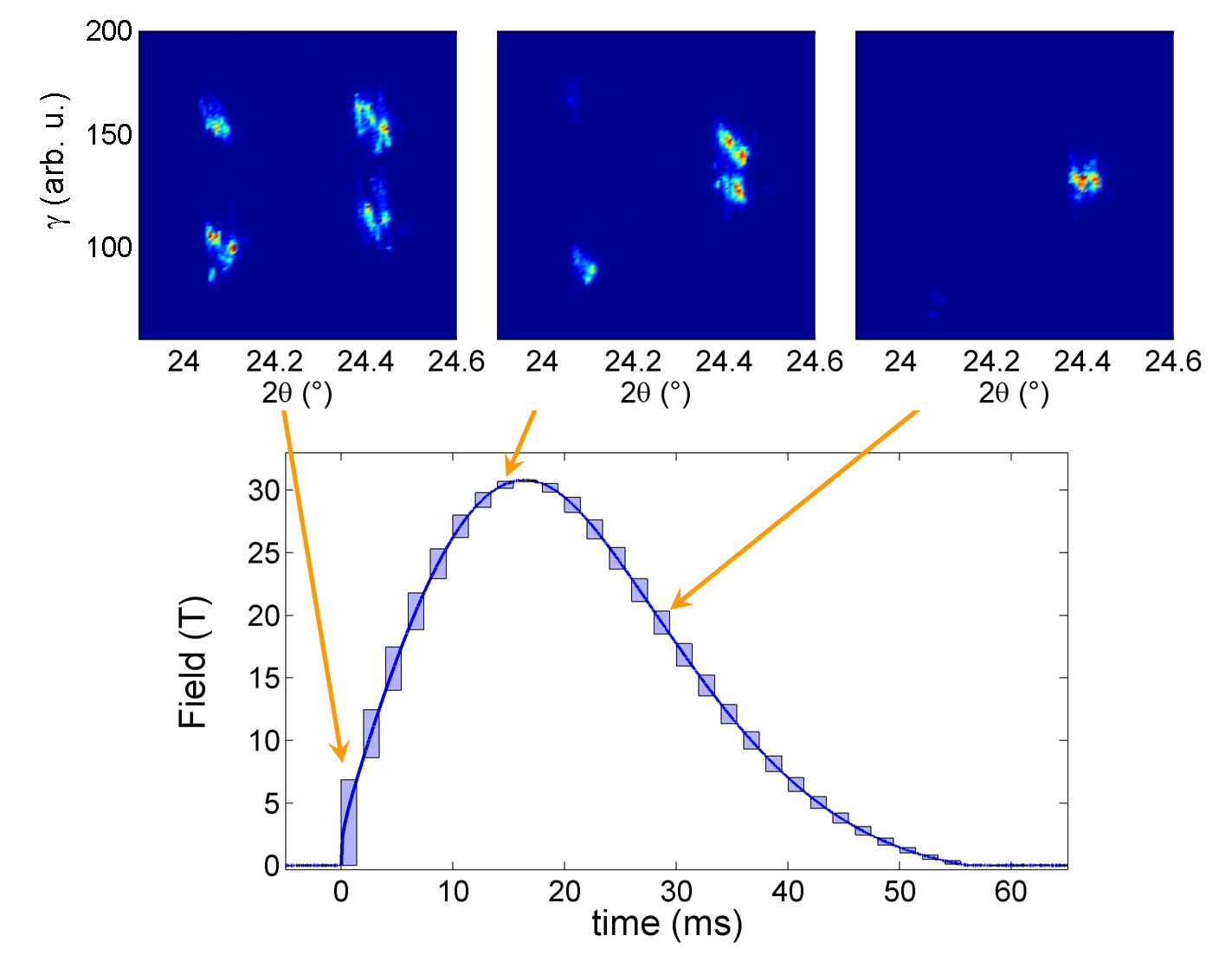
The high frame rate of this detector perfectly matches the time structure of magnetic field pulse and enables multi-frame acquisition as already implemented in other x-ray techniques combined with pulsed fields Strohm et al. (2011). Similarly, synchronized with the field pulse, the MAXIPIX detector allows to follow the evolution of Bragg reflections as a function of time during a magnetic field pulse. In our experiments, each frame was exposed during 1.4 ms with a data transfer time of 0.6 ms resulted in an effective frame rate of 500. In this multi-frame acquisition mode, 50 frames were acquired for each magnetic field pulse, with two frames being recorded before the triggering of the pulse (see Fig. 10).
Raw data obtained are images of the reciprocal space with the scattering angle 2 along the horizontal direction. For the following, we will call the out of diffraction plane angle (vertical direction on raw images) by analogy to the detector arm. To extract the diffracted intensity as a function of time, frames measured in a single magnetic field pulse are first -integrated. The resulting 2-scans are then concatenated to form an image showing the diffracted intensity at specified scattering angles as a function of time. Typical plots obtained are presented figure 11. From these plots, it is then easy to get the intensity variations as a function of field.
IV.2 Field-induced phase transition in Fe1.1Te
First experiments were performed on Fe1.1Te single crystals. This compound belongs to the parent phases Fe1+xTe of chalcogenide superconductors Fe(Te,Se), which are the subject of intense studies because of their similarities and differences with high Tc cuprates. At high temperatures, Fe1+xTe compounds crystallize in the tetragonal P4/nmm structure Bao et al. (2009). Upon cooling the temperature through 57-70 Johnston (2010); Bao et al. (2009); Li et al. (2009); Rodriguez et al. (2011); Rößler et al. (2011), they undergo a first order phase transition leading to an antiferromagnetic (AFM) ordering associated with a structural distortion lowering the high temperature tetragonal paramagnetic lattice symmetry. For 0.12, the low temperature phase is monoclinic P21/m with a bicollinear AFM order whereas it is orthorhombic Pnmm with a strongly incommensurate helimagnetic spin order for 0.12 Bao et al. (2009); Li et al. (2009); Martinelli et al. (2010); Rodriguez et al. (2011). In these systems, magneto-elastic couplings are suspected to play a crucial role on their magnetic and electronic properties Paul, Cano, and Sengupta (2011); Tokunaga et al. (2012). Recently, an irreversible alignment of the AFM moments inducing a step-like anomaly in the magnetization was reported at low temperature and high field for Fe1.1Te single crystals Knafo et al. (2013). The critical field associated with this transition was denoted . A spin-flop-like reorientation of the AFM moments was suggested to explain this behavior, keeping in mind that the microscopic model should also describe the remanent moment reorientation once a magnetic field higher than is applied. To probe magneto-elastic effects that could be the cause of this behavior, we performed diffraction experiments on Fe1.1Te single crystals over the temperature range 70 and in pulsed magnetic fields up to 31. The detailed study of this system will be published elsewhere Fabrèges et al. . Here, only first results obtained illustrating the possibilities offered by our pulsed field system as regards of field, temperature and stability will be shown.
Single crystals of Fe1.1Te, grown by a modified Bridgman method, were kindly provided by Viennois and Giannini from Geneva University (Switzerland). A single crystal sample was mounted on the sample holder as described above. The sample was aligned with [1 0 0] and [0 0 1] axes in the diffraction plane giving access to Bragg reflections in the (H, 0, L) zone axes. The magnetic field was applied along the b-axis of the crystal. X-ray diffraction images were recorded as described above, using an x-ray photon energy of 31 keV.
We first performed zero field measurements to collect the temperature dependence of several Bragg reflections at different scattering angles. The high temperature tetragonal (400) and (404) Bragg peaks were, for instance, measured. These measurements confirm that our Fe1.1Te sample undergoes a structural transition from a tetragonal lattice symmetry at room temperature to a monoclinic one below 58, in agreement with previous results Rößler et al. (2011); Knafo et al. (2013). Our observations are consistent with the previously determined monoclinic lattice parameters, 3.83378(6) Å, 3.78667(8) Å, 6.246427(8) Å and 89.359(1)∘. The inserts in figure 10 show typical data acquired during a single magnetic field pulse at 23, below the phase transition. The leftmost image, acquired at 0 before the field pulse, clearly shows four reflections corresponding to the twinned monoclinic domains that arise at the structural phase transition Tokunaga et al. (2012). The peaks are identified as (400) at 224.10∘ and (040) at 224.40∘.
Next, we applied the magnetic field. The evolution at 23 of the (400)/(040) Bragg reflections during a 31 pulse is illustrated, for instance, by the three selected frames shown on figure 10-top. At the beginning of the pulse, four Bragg peaks are observed, as described above. Then, during the rise of the field, a progressive disappearance of the low angle Bragg peaks at the benefit of the high angle ones occurs. Finally only one peak remains at the end of the pulse as shown on the frame measured during the fall of the pulse (Fig. 10, right frame). This clearly reveals a magneto-crystalline selection of domain leading to the detwinning of the crystal. This behavior was observed for all temperatures in the range 50, the critical field required to completely detwin the crystal increasing when temperature decreases.
Figure 11-bottom shows the time dependence of the integrated intensities of the (400)/(040) pair of reflections measured at 1.6 when a 31 magnetic field pulse was applied. Only slight oscillations are visible, both peaks keeping their intensity during all the pulse. This clearly indicates that the high field limit of our experimental set-up is not enough to detwin this compound at low temperature. This behavior is in agreement with high field magnetization measurements Knafo et al. (2013) and will be further explained elsewhere Fabrèges et al. .
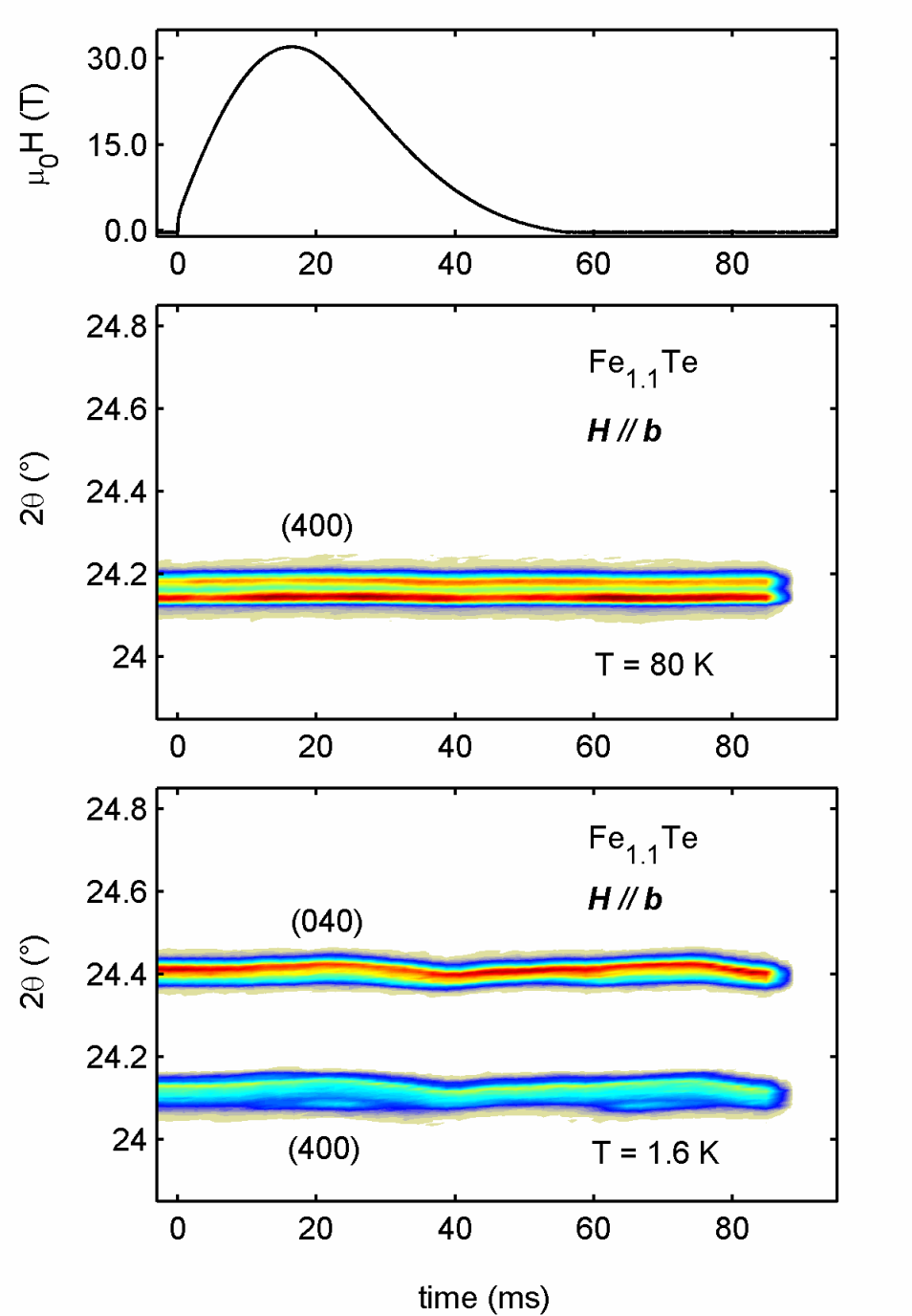
Above the Néel temperature (Fig. 11, middle) no evolution of the integrated intensity of the different Bragg peaks measured was detected as a function of time (and therefore as a function of field), clearly indicating a quite good sample stability with regard to the beam during a pulse.
This first experiment thus shows that applying high magnetic field results in magneto-crystalline domain selection in Fe1.1Te. This behavior can be directly followed during the entire magnetic field pulse thanks to the multi-frame acquisition mode allowed by the fast two-dimensional pixel detector associated with the pulsed field set-up developed for single crystal x-ray diffraction. This promising results open the door to the investigation of the - phase diagram of this material in the limits offered by our experimental set-up.
V Conclusion
In summary, we have constructed a split-pair magnet implemented in a novel cryogenic environment to perform high field single crystal x-ray diffraction measurements at synchrotron sources. This new device offers a panoramic access to x-rays allowing measurements at any scattering angle. It provides magnetic fields up to 31 with a long pulse duration (rise time of 16.5), which is of great advantage for studying metallic samples and hysteretic effects. Furthermore, a temperature as low as 1.5 can be maintained on the sample for more than ten hours using the closed cycle mode of the 4He cryostat inserted into the bore of the magnet.
During the commissioning of this apparatus, particular attention was given to the problem of field-pulse induced vibrations of the sample. We succeeded to limit the sample rotation induced by magnetic field pulse to during the first half of the pulse. This rotation is well below the mosaicity of most single crystal samples of interest for high field studies.
Combined with a fast two-dimensional pixel detector adapted to the time structure of the field pulse, it offers the possibility to follow the intensity changes of several Bragg peaks at different scattering angles simultaneously and throughout the whole duration of the pulse.
Improvements could be carried out on the duty cycle of the experiment by incorporating LN2 cooling channels in the design of the coil. This will decrease the cooling time of the coil but this will come at the expense of the maximal field or will require higher energy.
This device offers the opportunity to investigate small crystallographic changes, such as magneto-elastic effects, field induced symmetry breaking or charge order that could occur in strongly correlated electrons systems like, e.g., high superconductors, quantum spin systems or heavy fermions materials.
Acknowledgements.
The authors would like to thank F. Lecouturier and N. Ferreira of the LNCMI-T/CNRS for the characterization of the wire conductor (resistivity and wire strength measurements). J.-M. Lagarrigue and L. Bendichou who machined the steel spacers and other pieces required for the coil building are also greatly acknowledged. At the ESRF, we would like to thank H.-P. Van der Kleij for lending us his autocollimator, P. Van Vaerenbergh and P. Bernard for the different mounting systems developed to reduce vibrations, and P. van der Linden for his help with cryogenics. The authors acknowledge the ESRF for granting the beam time for these developments and experiments. The safety issues of the equipment were addressed with the help of ESRF Safety Group. The MAXIPIX photon-counting pixel detector was lent to the authors by the ESRF detector pool. Part of this research was funded by the ANR (Grants N. ANR-05-BLAN-0238 and ANR-10-BLAN-0431).References
- Matsuda et al. (2004) Y. H. Matsuda, Y. Ueda, H. Nojiri, T. Takahashi, T. Inami, K. Ohwada, Y. Murakami, and T. Arima, Physica B-condensed Matter 346, 519 (2004).
- Narumi et al. (2006a) Y. Narumi, K. Kindo, K. Katsumata, M. Kawauchi, C. Broennimann, U. Staub, H. Toyokawa, Y. Tanaka, K. Kikkawa, T. Yamamoto, M. Hagiwara, T. Ishikawa, and H. Kitamura, Journal of Physics, Conference Series 51, 494 (2006a).
- Narumi et al. (2006b) Y. Narumi, K. Kindo, K. Katsumata, M. Kawauchi, C. Broennimann, U. Staub, H. Toyokawa, Y. Tanaka, A. Kikkawa, T. Yamamoto, M. Hagiwara, T. Ishikawa, and H. Kitamura, Journal of Synchrotron Radiation 13, 271 (2006b).
- Matsuda et al. (2006) Y. H. Matsuda, T. Inami, K. Ohwada, Y. Murata, H. Nojiri, Y. Murakami, H. Ohta, W. Zhang, and K. Yoshimura, Journal of the Physical Society of Japan 75, 024710 (2006).
- Islam et al. (2009) Z. Islam, J. P. C. Ruff, H. Nojiri, Y. H. Matsuda, K. A. Ross, B. D. Gaulin, Z. Qu, and J. C. Lang, Review of Scientific Instruments 80, 113902 (2009).
- Islam et al. (2012) Z. Islam, D. Capatina, J. P. C. Ruff, R. K. Das, E. Trakhtenberg, H. Nojiri, Y. Narumi, U. Welp, and P. C. Canfield, Review of Scientific Instruments 83, 035101 (2012).
- van der Linden et al. (2008) P. J. E. M. van der Linden, O. Mathon, C. Strohm, and M. Sikora, Review of Scientific Instruments 79, 075104 (2008).
- Yoshii et al. (2009) S. Yoshii, K. Ohoyama, K. Kurosawa, H. Nojiri, M. Matsuda, P. Frings, F. Duc, B. Vignolle, G. L. J. A. Rikken, L. P. Regnault, S. Michimura, and F. Iga, Physical Review Letters 103, 077203 (2009).
- Chavanne (2007) J. Chavanne, in Highlights (ESRF, 2007) p. 127.
- Paolasini et al. (2007) L. Paolasini, C. Detlefs, C. Mazzoli, S. Wilkins, P. P. Deen, A. Bombardi, F. de Bergevin, F. Yakhou, J. P. Valade, I. Beslavetz, A. Fondacaro, G. Peppelin, and P. Bernard, J. Synchrotron Rad. 14, 301 (2007).
- Ponchut et al. (2011) C. Ponchut, J. Rigal, J. Clément, E. Papillon, A. Homs, and S. Petitdemange, Journal of Instrumentation 6, C01069 (2011).
- Llopart et al. (2002) X. Llopart, M. Campbell, R. Dinapoli, D. San Segundo, and E. Pernigotti, Nuclear Science, IEEE Transactions on 49, 2279 (2002).
- Llopart et al. (2007) X. Llopart, R. Ballabriga, M. Campbell, L. Tlustos, and W. Wong, Nuclear Instruments and Methods in Physics Research Section A: Accelerators, Spectrometers, Detectors and Associated Equipment 581, 485 (2007).
- Strohm et al. (2011) C. Strohm, F. Perrin, M.-C. Dominguez, J. Headspith, P. van der Linden, and O. Mathon, Journal of Synchrotron Radiation 18, 224 (2011).
- Bao et al. (2009) W. Bao, Y. Qiu, Q. Huang, M. A. Green, P. Zajdel, M. R. Fitzsimmons, M. Zhernenkov, S. Chang, M. Fang, B. Qian, E. K. Vehstedt, J. Yang, H. M. Pham, L. Spinu, and Z. Q. Mao, Phys. Rev. Lett. 102, 247001 (2009).
- Johnston (2010) D. C. Johnston, Advances in Physics 59, 803 (2010).
- Li et al. (2009) S. Li, C. de la Cruz, Q. Huang, Y. Chen, J. W. Lynn, J. Hu, Y.-L. Huang, F.-C. Hsu, K.-W. Yeh, M.-K. Wu, and P. Dai, Phys. Rev. B 79, 054503 (2009).
- Rodriguez et al. (2011) E. E. Rodriguez, C. Stock, P. Zajdel, K. L. Krycka, C. F. Majkrzak, P. Zavalij, and M. A. Green, Phys. Rev. B 84, 064403 (2011).
- Rößler et al. (2011) S. Rößler, D. Cherian, W. Lorenz, M. Doerr, C. Koz, C. Curfs, Y. Prots, U. K. Rößler, U. Schwarz, S. Elizabeth, and S. Wirth, Phys. Rev. B 84, 174506 (2011).
- Martinelli et al. (2010) A. Martinelli, A. Palenzona, M. Tropeano, C. Ferdeghini, M. Putti, M. R. Cimberle, T. D. Nguyen, M. Affronte, and C. Ritter, Phys. Rev. B 81, 094115 (2010).
- Paul, Cano, and Sengupta (2011) I. Paul, A. Cano, and K. Sengupta, Phys. Rev. B 83, 115109 (2011).
- Tokunaga et al. (2012) M. Tokunaga, T. Kihara, Y. Mizuguchi, and Y. Takano, Journal of the Physical Society of Japan 81, 063703 (2012).
- Knafo et al. (2013) W. Knafo, R. Viennois, G. Ballon, X. Fabrèges, F. Duc, C. Detlefs, J. Léotin, and E. Giannini, Phys. Rev. B 87, 020404 (2013).
- (24) X. Fabrèges, F. Duc, T. Roth, C. Detlefs, W. Knafo, R. Viennois, and E. Giannini, (unpublished).