Spin filtering in a magnetic barrier structure:
in-plane spin orientation
Abstract
We investigate ballistic spin transport in a two dimensional electron gas system through magnetic barriers of various geometries using the transfer matrix method. While most of the previous studies have focused on the effect of magnetic barriers perpendicular to the two dimensional electron gas plane, we concentrate on the case of magnetic barriers parallel to the plane. We show that resonant oscillation occurs in the transmission probability without electrostatic potential modulation which is an essential ingredient in the case of ordinary out-of-plane magnetic barriers. Transmission probability of the in-plane magnetic barrier structure changes drastically according to the number of barriers and also according to the electrostatic potential modulation applied in the magnetic barrier region. Using a hybrid model consisting of a superconductor, ferromagnets, and a two dimensional electron gas plane, we show that it can serve as a good in-plane oriented spin selector which can be operated thoroughly by electrical modulation without any magnetic control.
Semiconductor device including magnetic barriers has recently attracted much attention as a spin device, because it circumvents the resistance mismatch problem in the spin injection process, which is one of the main obstacles in realization of the Datta-Das-type spin transistordatta . Very recently the magnetic barrier study is expanded to a graphenegraphene and a topological insulatortopo with great interests. Magnetic barrier structure has been introduced by using vortices in superconductors, superconducting(SC) masks or ferromagnetic material stripes on a two dimensional electron gas(2DEG). Since the 2DEG having a perpendicular magnetic field has been studied intensively in experiments, for example, Quantum Hall effect, observation of Commensurability effects and Novel giant magnetoresistance, most of the previous theoretical studiespeeters ; ihm ; nammee1 on a magnetic barrier structure have carried on the out-of-plane magnetic barrier system with a purpose to use the system as an out-of plane oriented spin filter or a spin injection device. However, in some experiments like those on Spin valve and Spin Hall Effectkimura ; tinkham ; Lu ; Wees , spin orientation is along the 2DEG plane and an in-plane oriented spin filter or a spin injection device is in order, i.e., an in-plane magnetic barrier system start to draw attention.bijl ; zhai ; wang .
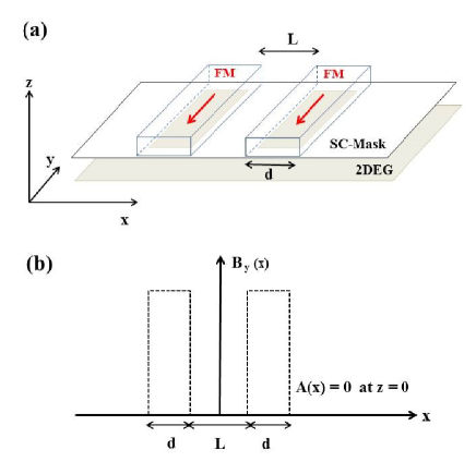
The aim of our work is to investigate the ballistic transport properties through an in-plane magnetic barrier system in 2DEG. In this system, it is easier to have tunneling process compared to an out-of-plane magnetic barrier system because the in-plane barrier system has no unwanted magnetic barrier due to vector potentialihm . We calculate spin-dependent transmission coefficients for double and triple in-plane magnetic barrier systems with/without external electrostatic modulation across a barrier using transfer matrix method. Schematic illustration for the possible realization of the in-plane magnetic barrier system is shown in Fig. 1(a). The device consists of ferromagnets(FM) and a superconducting(SC) mask having openings on top of a 2DEG system. The SC mask is used to provide the magnetic field profile demanded in the system as shown in Fig. 1(b).
The Hamiltonian with effective mass , and effective -factor with electrostatic potential is;
| (1) |
where denotes spin up/spin down of the electron. The in-plane magnetic barrier, which is square-function like, assumes the magnetic field along the y direction at two locations and ;
| (2) |
Here, is the Heaviside step function, B is the magnetic field strength in barriers, is the distance between the openings in the SC mask and is the width of each opening. In Fig. 1(b), the dotted line indicates the in-plane magnetic profile in the 2DEG under the SC mask as written in Eq.(2). Vector potential , in Landau gauge, is given by , which vanishes at the 2DEG plane (). As a result, the transverse motion is decoupled from the longitudinal one. This formalism also applies to with , which provides longitudinal spin orientation in 2DEG.
The system is translation-invariant along the y direction, and the Schrödinger equation in two dimensional space is simplified by using ;
| (3) |
where we use units of length , energy , and is the magnetic field scaling unit. In the out-of-plane magnetic barrier system, it is essential to include electrostatic potential in order to compensate for unwanted step-like potential barriers coming from the vector potential ihm . However, the vector potential does not appear in Eq. (3) since it becomes zero at the 2DEG plane and, therefore, it is not essential to include electrostatic potential in the in-plane magnetic barrier system. Notice that the Zeeman term in Eq. (3) plays a role of an effective potential barrier for spin-up() electrons, while it acts like an effective potential well for spin-down() electrons. Hereinafter, a magnetic barrier should be interpreted as an effective potential well for a spin-down() electron.
Based on the above Shrödinger equation, transmission probability is calculated by the standard transfer matrix method. Transfer matrices for the magnetic barriers and for the well confined by the barriers are ;
| (6) | |||||
| (9) |
where and . The transmission probability is obtained from the transmission coefficient of the wavefunction after tunneling through the magnetic barriers by using the transfer matrices.
| (10) |
where are elements of the transfer matrix for double barriers.
In our numerical calculation, since the better spin filtering effect is expected in a material with large and ihm ; nammee1 , material parameters of HgCdTe are used as follows: the effective mass , -factor , energy unit meV, magnetic length nm, and the magnetic scaling unit T.
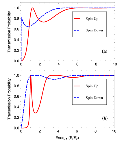
Figure 2 shows the transmission probability of the in-plane double magnetic barrier system with for two different magnetic barrier widths. For minimum energy requirement for electron tunneling, is chosen for qualitative calculation. The transmission probability of both spins shows clear oscillating behavior as a function of incident electron’s energy, even when the electrostatic potential is absent.
In Fig. 2(a), sharp resonance peaks are clearly seen for both spin-up and spin-down electrons. As magnetic barrier width increases, however, the spin-down resonance peak is broadened due to the lack of barrier formation. In Fig. 2(b), since the total structure length increases as the barrier width increases, energy difference between two resonant peaks for a spin-up electron decreases and the better negative spin polarization is achieved around compared to the case of Fig. 2(a).
Figure 3 shows the transmission probability and corresponding tunneling spin polarization for an in-plane triple magnetic barrier system as a function of incident electron’s energy with electrostatic potential applied.
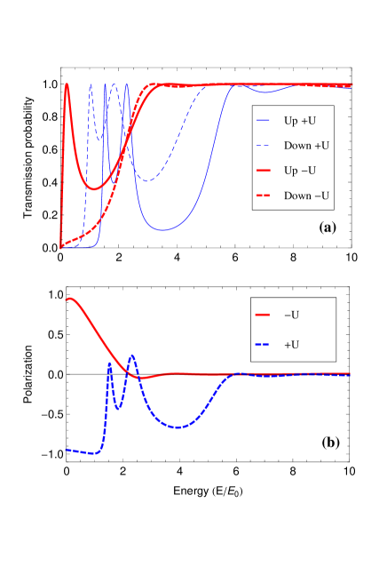
The tunneling spin polarization is defined by
| (11) |
As the number of barriers increases, a resonance peak splitting appears clearly. In the triple case, in Eq.(10) are obtained from . Since affects on the height of effective potential barrier, when positive electrostatic potential is applied at the magnetic barrier region, resonant peaks move to higher energy than negative case. When , the resultant effective potential for spin-down electrons becomes positive, and the spin-down electrons experience a barrier instead of a well. As a result, the resonance peak splitting appears also in the spin-down case, which is shown as the thin dashed line in Fig. 3(a).
Figure 3(b) shows tunneling spin polarization corresponding to Fig. 3(a). Notice that in the low energy regime of , the spin polarization can be switched between spin-up and spin-down by reversing the sign of the electric potential . This implies that in-plane spin orientation of injected currents through the triple magnetic barrier structure can be manipulated electrically.
In conclusion, the transmission properties of a two-dimensional electron gas system with in-plane magnetic barriers are investigated. Spin dependent resonance oscillation occurs in the transmission probability even without electrostatic potential applied, although it can be used to control the spin current. The transmission property and the current spin polarization can be manipulated efficiently by the number of barriers as well as by electrostatic potential modulation. As a result of this work, the in-plane triple magnetic barrier structure can serve as a good in-plane oriented spin selector which can be operated thoroughly by electrical modulation without any magnetic control.
Acknowledgements.
We are grateful to J. W. Kim for helpful discussions. This research was supported by Basic Science Research Program through the National Research Foundation of Korea(NRF) funded by the Ministry of Education, Science and Technology (grant 2012R1A1A2006303 and 2010-0021328).References
- (1) S. Datta and B. Das, Appl. Phys. Lett. 56, 665 (1990).
- (2) M. Ramenzani Masir, P. Vasilopoulos, and F. M. peeters, Appl. Phys. Lett. 93, 242103 (2008).
- (3) Zhenhua Wu, F. M. peeters, and Kai Chang, Phys. Rev. B 82, 115211 (2010).
- (4) G. Papp and F. M. peeters, Appl. Phys. Lett 78, 2184 (2001).
- (5) K. C. Seo, G. Ihm, K.-H. Ahn, and S. J. Lee, J. Appl. Phys. Lett. 95, 7252 (2004).
- (6) J. W. Kim, N. Kim, S. J. Lee, and T. W. kang, Semicon. Sci. Technol. 21, 647-653 (2006).
- (7) T. kimura, Y. Otani, T. Sato, S. Takahashi, and S. Maekawa, Phys. Rev. Lett. 98, 156601 (2007).
- (8) S. O. Valenzuela and M. Tinkham, Nature 442, 176-179 (2006).
- (9) Y. M. Lu, J. W. Cai, S. Y. Huang, D. Qu, B. F. Miao, and C. L. Chien, Phys. Rev. B 87, 2204409(R) (2013).
- (10) N. Vliestra, J. Shan, V. Castel, and B. J. van Wees, Phys. Rev. B 87, 184421) (2013).
- (11) E. van der Bijl, R. E. Troncoso, and R. A. Duine, Phys. Rev. B. 88, 064417 (2013).
- (12) Feng Zhai and H. Q. Xu, Appl. Phys. Lett. 88, 032502 (2006).
- (13) Y. Wang, Y. Jiang, X. W. Zhang, and Z. G. Yin, J. Appl. Phys. Lett. 108, 073703 (2010).